- Мікропроцесорна техніка

Содержание
- 2. PSoC@3/5 VDAC8+DMA PSoC Creator 4.2 Designing with PSoC 3/5
- 3. Модулі PSoC@3/5
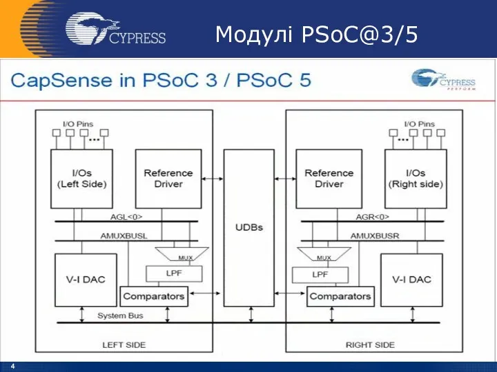
- 4. Модулі PSoC@3/5
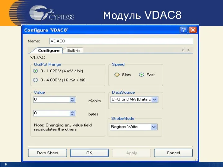
- 5. Модуль VDAC8
- 6. Модуль VDAC8
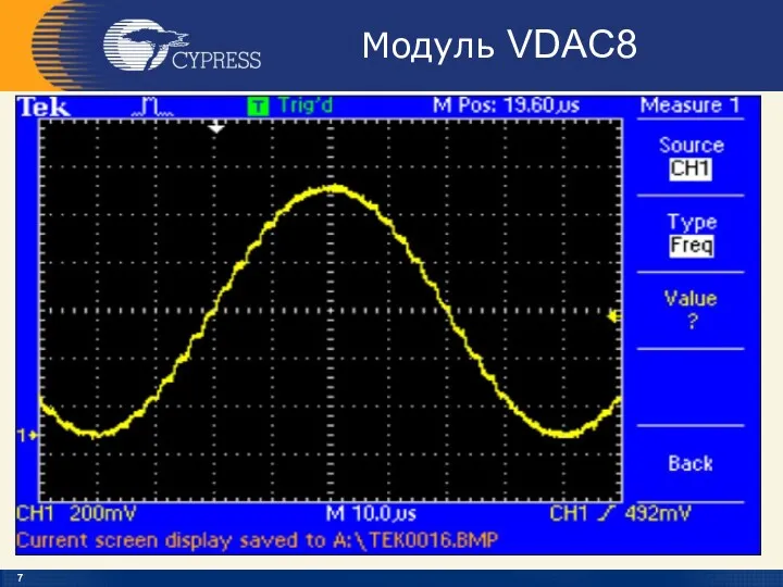
- 7. Модуль VDAC8
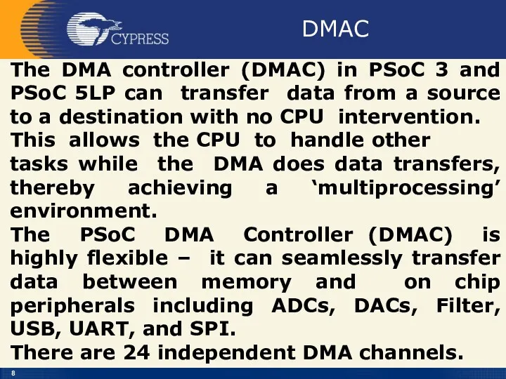
- 8. DMAC The DMA controller (DMAC) in PSoC 3 and PSoC 5LP can transfer data from a
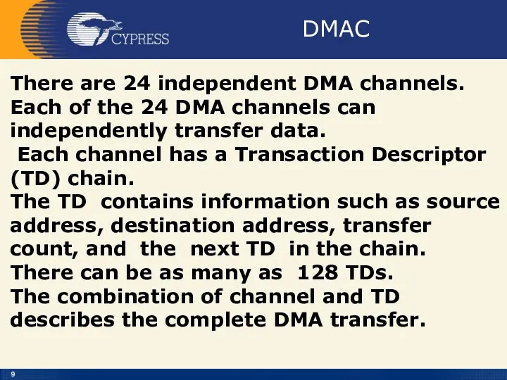
- 9. DMAC There are 24 independent DMA channels. Each of the 24 DMA channels can independently transfer
- 10. DMAC
- 11. DMA Channel
- 12. Memory-to-Peripheral Transfer
- 13. Memory-to-Peripheral Transfer
- 14. Channel Configuration
- 15. TD[0] Configuration
- 16. DMA Channel Component
- 17. DMA component Configuration
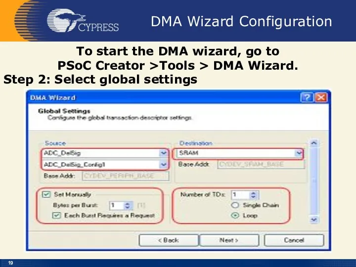
- 18. DMA Wizard Configuration To start the DMA wizard, go to PSoC Creator >Tools > DMA Wizard.
- 19. DMA Wizard Configuration To start the DMA wizard, go to PSoC Creator >Tools > DMA Wizard.
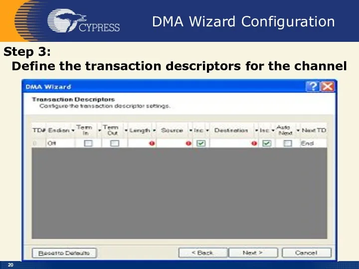
- 20. DMA Wizard Configuration Step 3: Define the transaction descriptors for the channel
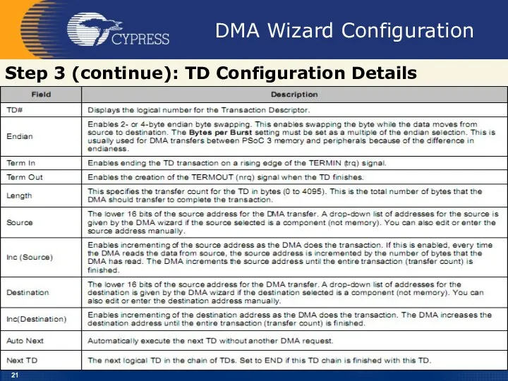
- 21. DMA Wizard Configuration Step 3 (continue): TD Configuration Details
- 22. DMA Wizard Configuration Step 4: Copy the code created by the DMA Wizard After the DMA
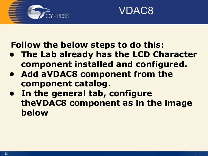
- 23. VDAC8 Follow the below steps to do this: The Lab already has the LCD Character component
- 24. Creator
- 25. File – New - Projekt
- 26. Empty PSoC 3.3 Design
- 27. VDAC8+DMA
- 28. VDAC8+DMA
- 29. VDAC8+DMA
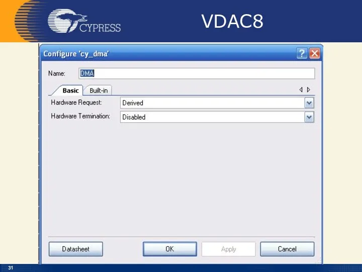
- 30. VDAC8
- 31. VDAC8
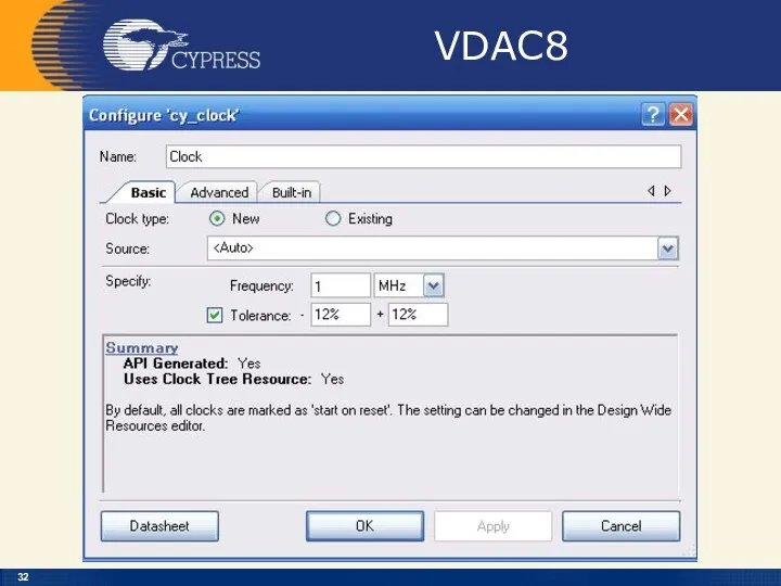
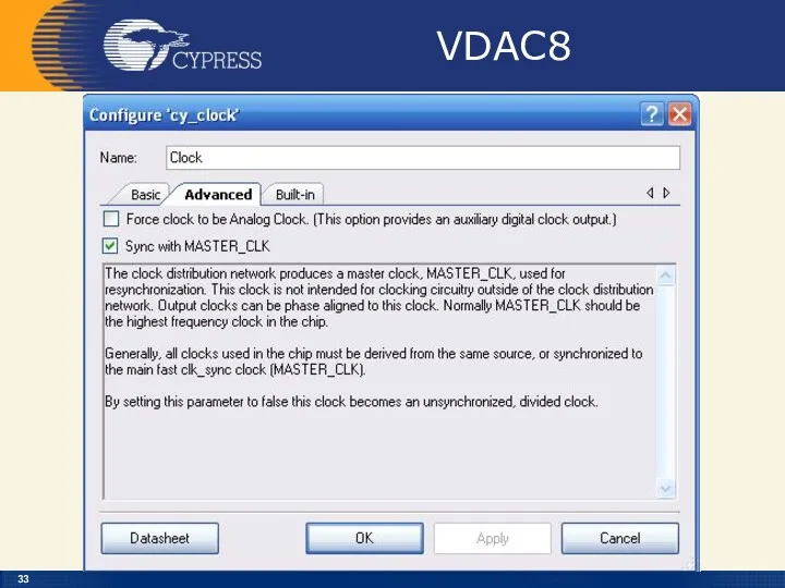
- 32. VDAC8
- 33. VDAC8
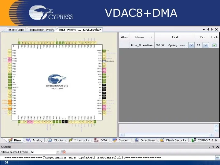
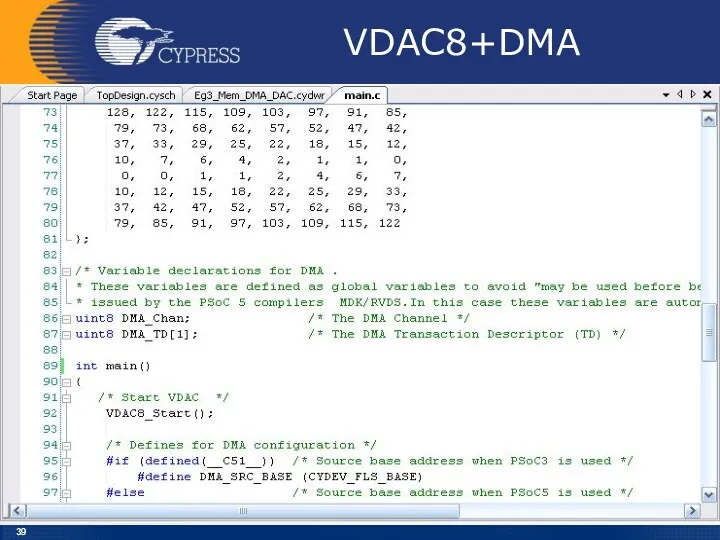
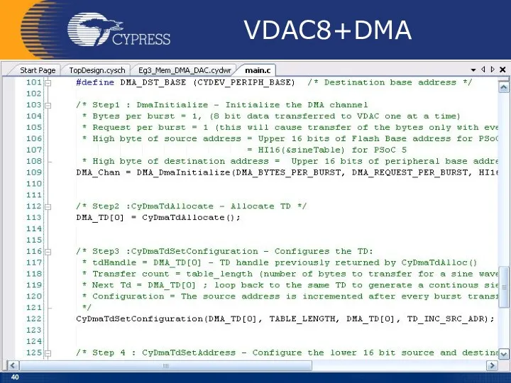
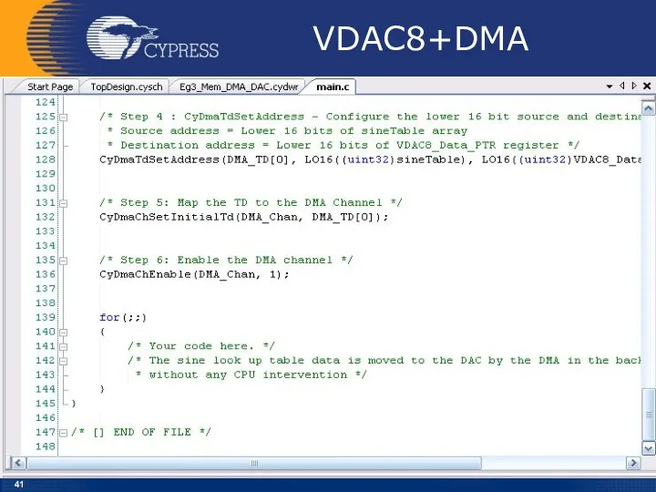
- 34. VDAC8+DMA
- 35. VDAC8+DMA
- 36. VDAC8+DMA
- 37. VDAC8+DMA
- 38. VDAC8+DMA
- 39. VDAC8+DMA
- 40. VDAC8+DMA
- 41. VDAC8+DMA
- 42. Test VDAC8+DMA Example : Memory-to-Peripheral Transfer – Mem_DMA_DAC The test setup is as follows: 1. Connect
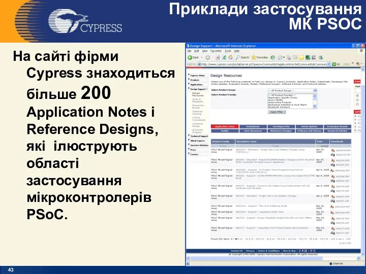
- 43. Приклади застосування МК PSOC На сайті фірми Cypress знаходиться більше 200 Application Notes і Reference Designs,
- 45. Скачать презентацию
PSoC@3/5
VDAC8+DMA
PSoC Creator 4.2
Designing with PSoC 3/5
PSoC@3/5
VDAC8+DMA
PSoC Creator 4.2
Designing with PSoC 3/5
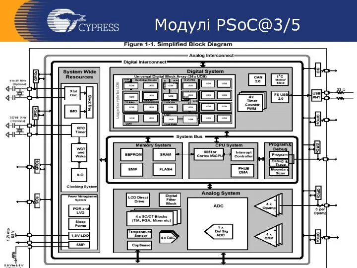
Модулі PSoC@3/5
Модулі PSoC@3/5
Модулі PSoC@3/5
Модулі PSoC@3/5
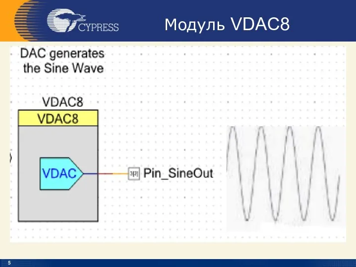
Модуль VDAC8
Модуль VDAC8
Модуль VDAC8
Модуль VDAC8
Модуль VDAC8
Модуль VDAC8
DMAC
The DMA controller (DMAC) in PSoC 3 and PSoC 5LP can
DMAC
The DMA controller (DMAC) in PSoC 3 and PSoC 5LP can
DMAC
There are 24 independent DMA channels.
Each of the 24 DMA
DMAC
There are 24 independent DMA channels.
Each of the 24 DMA
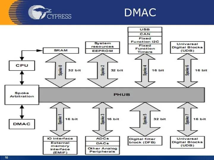
DMAC
DMAC
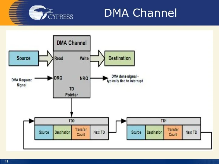
DMA Channel
DMA Channel
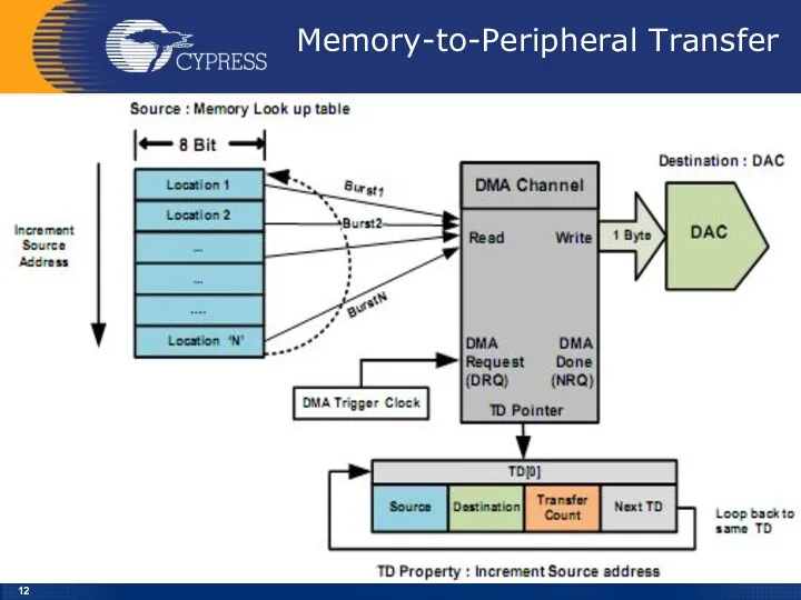
Memory-to-Peripheral Transfer
Memory-to-Peripheral Transfer
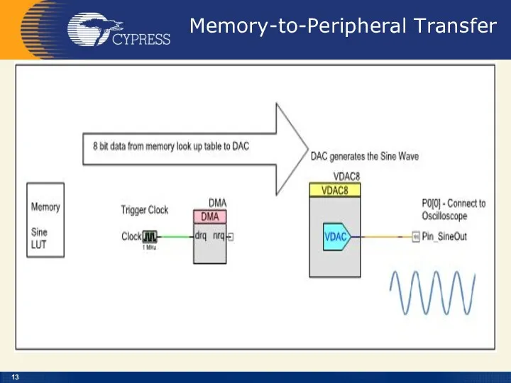
Memory-to-Peripheral Transfer
Memory-to-Peripheral Transfer
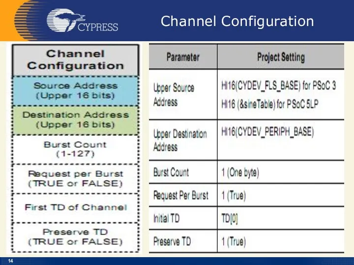
Channel Configuration
Channel Configuration
![TD[0] Configuration](/_ipx/f_webp&q_80&fit_contain&s_1440x1080/imagesDir/jpg/26282/slide-14.jpg)
TD[0] Configuration
TD[0] Configuration
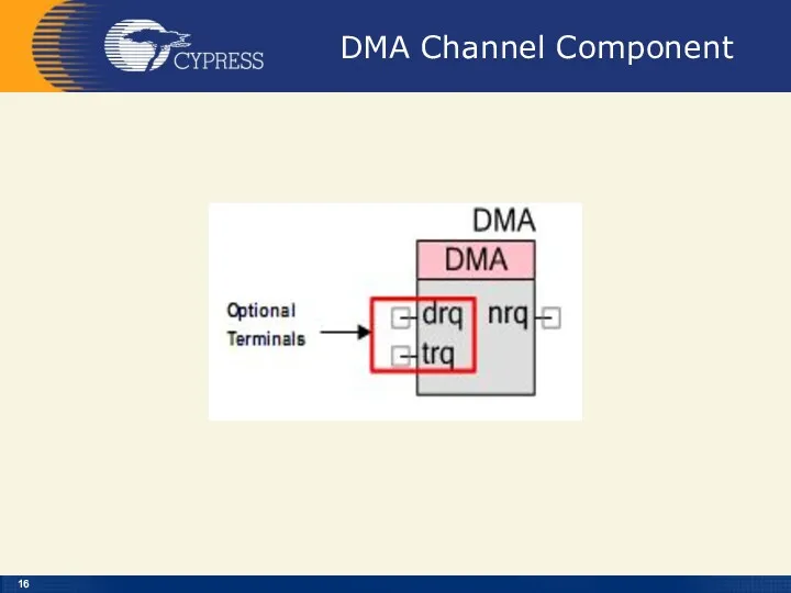
DMA Channel Component
DMA Channel Component
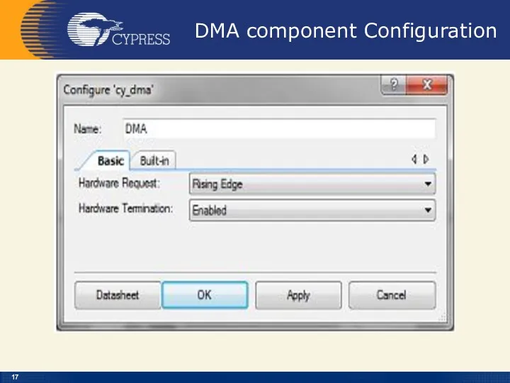
DMA component Configuration
DMA component Configuration
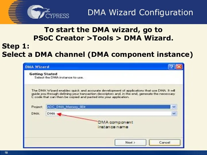
DMA Wizard Configuration
To start the DMA wizard, go to
PSoC
DMA Wizard Configuration
To start the DMA wizard, go to
PSoC
DMA Wizard Configuration
To start the DMA wizard, go to
PSoC
DMA Wizard Configuration
To start the DMA wizard, go to
PSoC
DMA Wizard Configuration
Step 3:
Define the transaction descriptors for the
DMA Wizard Configuration
Step 3:
Define the transaction descriptors for the
DMA Wizard Configuration
Step 3 (continue): TD Configuration Details
DMA Wizard Configuration
Step 3 (continue): TD Configuration Details
DMA Wizard Configuration
Step 4: Copy the code created by the
DMA Wizard Configuration
Step 4: Copy the code created by the
VDAC8
Follow the below steps to do this:
The Lab already has the
VDAC8
Follow the below steps to do this:
The Lab already has the
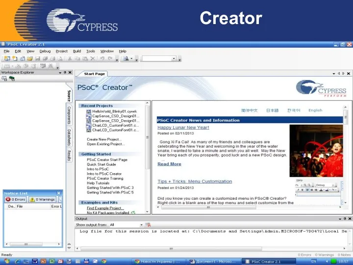
Creator
Creator
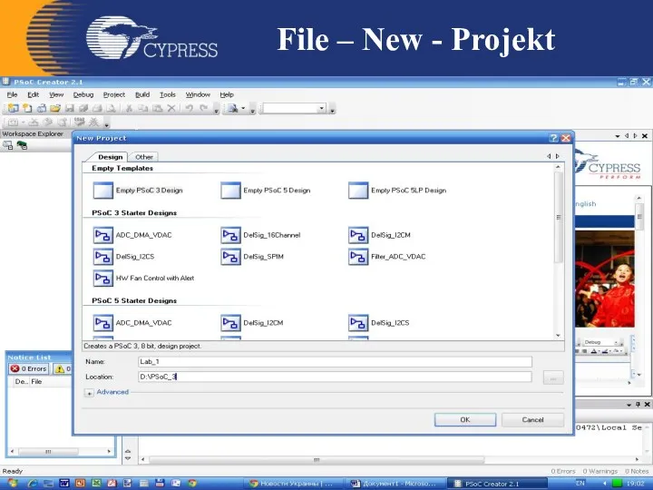
File – New - Projekt
File – New - Projekt
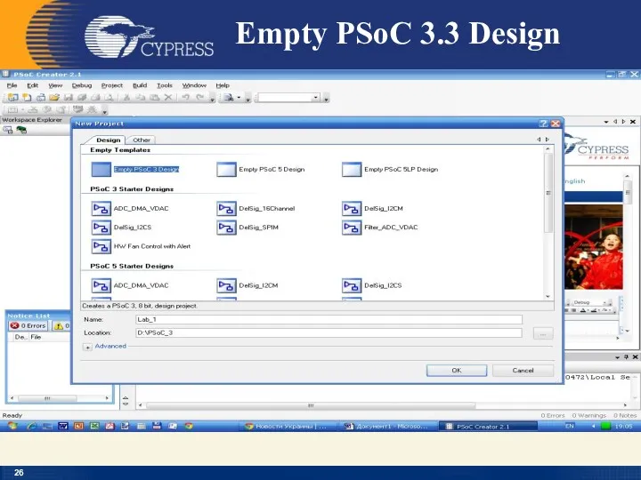
Empty PSoC 3.3 Design
Empty PSoC 3.3 Design
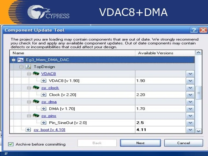
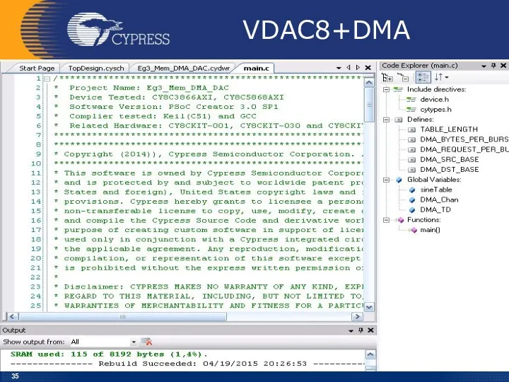
VDAC8+DMA
VDAC8+DMA
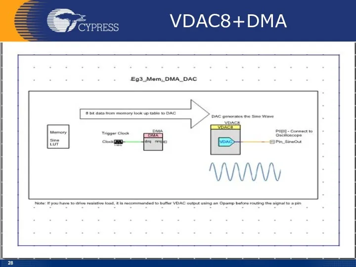
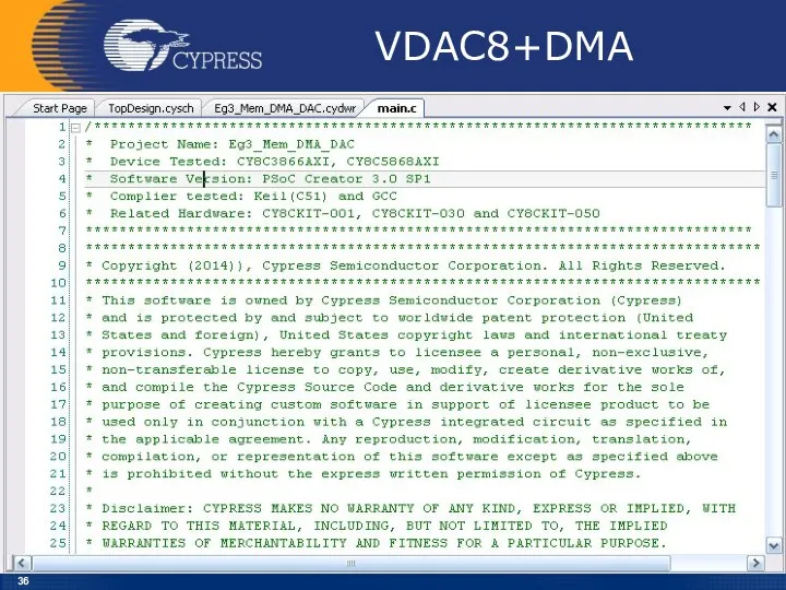
VDAC8+DMA
VDAC8+DMA
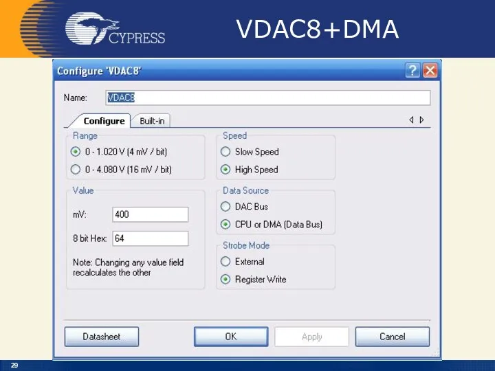
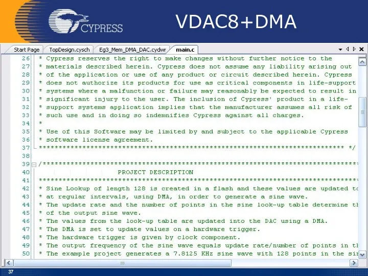
VDAC8+DMA
VDAC8+DMA
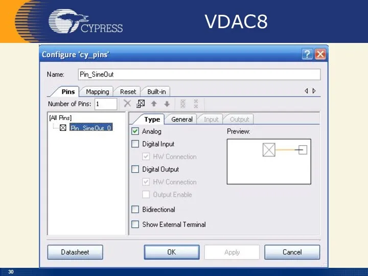
VDAC8
VDAC8
VDAC8
VDAC8
VDAC8
VDAC8
VDAC8
VDAC8
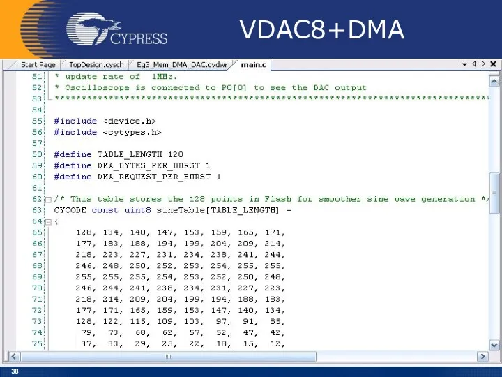
VDAC8+DMA
VDAC8+DMA
VDAC8+DMA
VDAC8+DMA
VDAC8+DMA
VDAC8+DMA
VDAC8+DMA
VDAC8+DMA
VDAC8+DMA
VDAC8+DMA
VDAC8+DMA
VDAC8+DMA
VDAC8+DMA
VDAC8+DMA
VDAC8+DMA
VDAC8+DMA
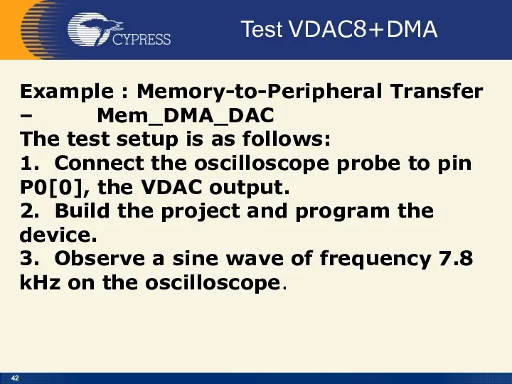
Test VDAC8+DMA
Example : Memory-to-Peripheral Transfer – Mem_DMA_DAC
The test setup is
Test VDAC8+DMA
Example : Memory-to-Peripheral Transfer – Mem_DMA_DAC
The test setup is
Приклади застосування
МК PSOC
На сайті фірми Cypress знаходиться більше 200 Application
Приклади застосування
МК PSOC
На сайті фірми Cypress знаходиться більше 200 Application
 Смутное время
 Приглашение к молитве
 Загрязнение воздуха в России
 Понятие об инфекционном процессе и инфекционных болезнях
 презентация на конкурсе Учитель года 2015 Через компетенции к вершинам успеха
 презентация к дню матери
 электронно дидактическая игра Безопасность дома и на улице
 Конструктивное моделирование юбок без изменения объемной формы
 Магический реализм в творчестве Г. Г. Маркеса
 The Beatles - британская рок-группа из Ливерпуля
 Детский православный журнал Божий лучик
 Артикуляционная гимнастика с биоэнергопластикой
 Петербургские традиции
 Мировое хозяйство 10 кл по Максаковскому В П
 Как написать отзыв о прочитанной книге
 Факторный анализ причин отказов скважин
 презентация Мой 1 класс
 Электронные выпрямители. Классификация. Идеализация схем выпрямления
 Луч света в нашем царстве (Рациональное и нерациональное использование электроэнергии дома и в школе)
 Творческий проект Семейные реликвии военных лет
 Использование системы альтернативной коммуникации с помощью карточек (PECS) в работе с детьми с ОВЗ
 d9-8045ce6a
 Адаптивные фильтры. Практическое применение (3)
 профессии на транспорте
 Литейное производство. Материалы, оборудование, принципиальная схема литья
 Раздел 1. Теоретико-методологические основы макроэкономического планирования. Тема 1. Макроэкономическое планирование
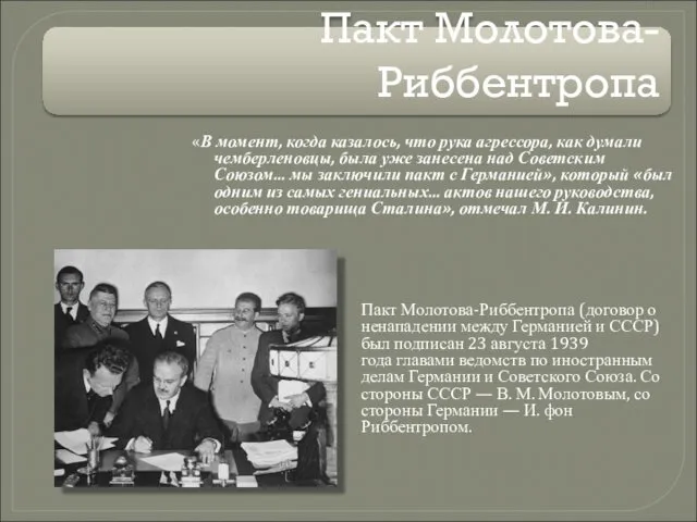 Пакт Молотова - Риббентропа
 Медико-социальные аспекты демографии