- Мікропроцесорна техніка PSoC Creator 4.2 Designing with PSoC 3/5. (Лекція 5)

Содержание
- 2. PSoC@3/5 IDAC8 PSoC Creator 4.2 Designing with PSoC 3/5
- 3. Модулі PSoC@3/5
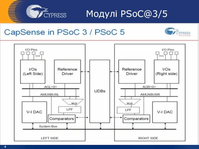
- 4. Модулі PSoC@3/5
- 5. IDAC8 Block Diagram IDAC8
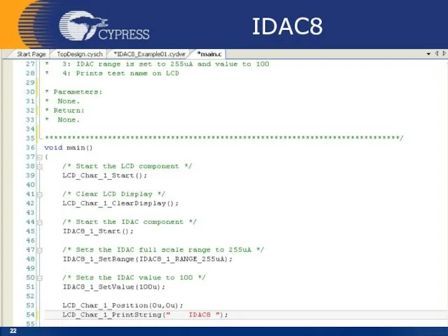
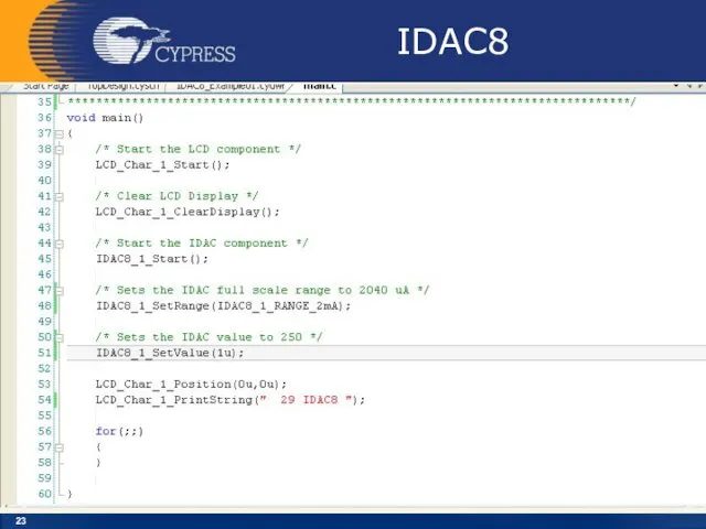
- 6. Lab_5 IDAC8
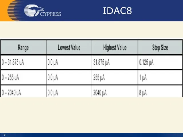
- 7. IDAC8
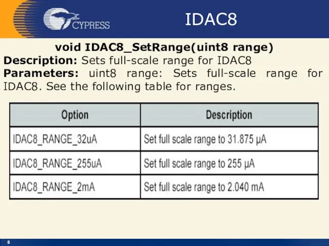
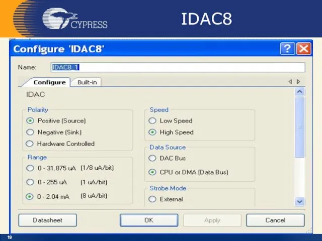
- 8. IDAC8 void IDAC8_SetRange(uint8 range) Description: Sets full-scale range for IDAC8 Parameters: uint8 range: Sets full-scale range
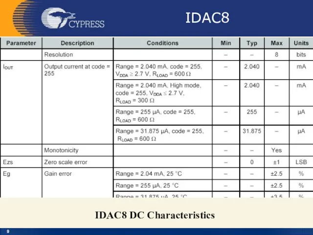
- 9. IDAC8 IDAC8 DC Characteristics
- 10. IDAC8 Iout – Analog The Iout terminal, the terminal on the right side of the symbol,
- 11. IDAC8 ipolarity – Input* The ipolarity input is an optional signal input pin. This pin can
- 12. IDAC8
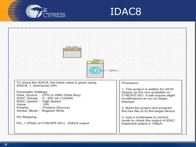
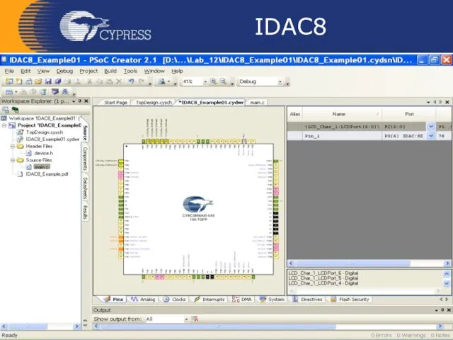
- 13. IDAC8 Follow the below steps to do this: The Lab already has the LCD Character component
- 14. Creator
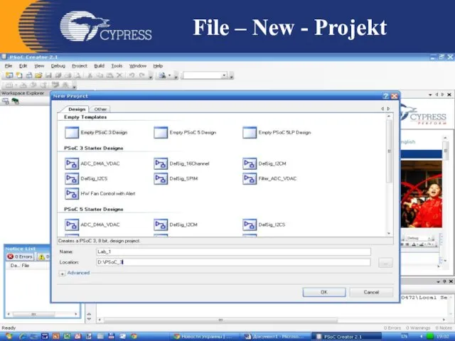
- 15. File – New - Projekt
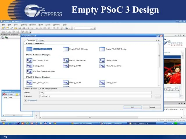
- 16. Empty PSoC 3 Design
- 17. IDAC8
- 18. IDAC8
- 19. IDAC8
- 20. IDAC8
- 21. IDAC8
- 22. IDAC8
- 23. IDAC8
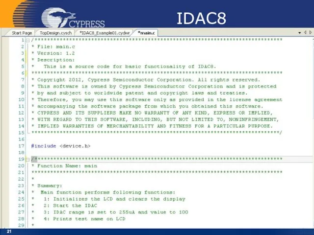
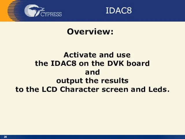
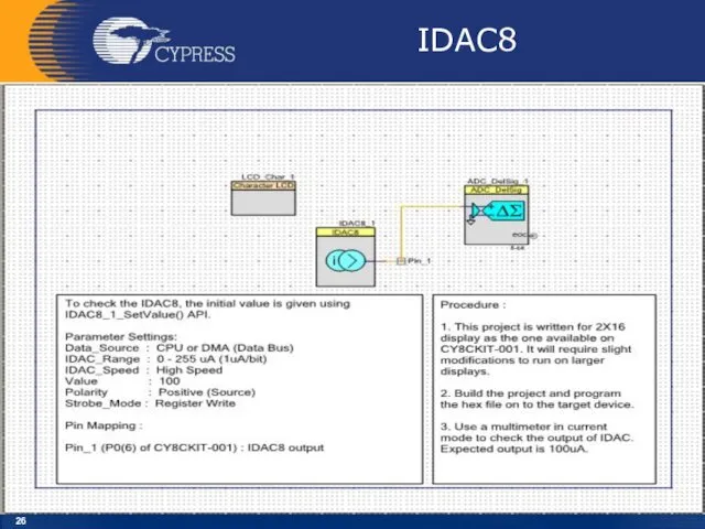
- 24. IDAC8 Overview: Activate and use the IDAC8 on the DVK board and output the results to
- 25. IDAC8 Зняти вольт-амперну характеристику напівпровідникового діода
- 26. IDAC8
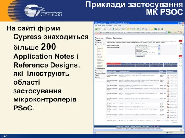
- 27. Приклади застосування МК PSOC На сайті фірми Cypress знаходиться більше 200 Application Notes і Reference Designs,
- 29. Скачать презентацию
PSoC@3/5
IDAC8
PSoC Creator 4.2
Designing with PSoC 3/5
PSoC@3/5
IDAC8
PSoC Creator 4.2
Designing with PSoC 3/5
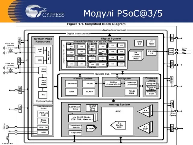
Модулі PSoC@3/5
Модулі PSoC@3/5
Модулі PSoC@3/5
Модулі PSoC@3/5
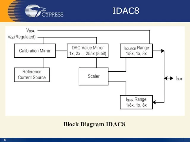
IDAC8
Block Diagram IDAC8
IDAC8
Block Diagram IDAC8
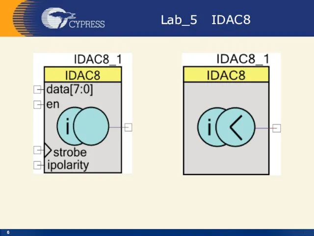
Lab_5 IDAC8
Lab_5 IDAC8
IDAC8
IDAC8
IDAC8
void IDAC8_SetRange(uint8 range)
Description: Sets full-scale range for IDAC8
Parameters: uint8 range:
IDAC8
void IDAC8_SetRange(uint8 range)
Description: Sets full-scale range for IDAC8
Parameters: uint8 range:
IDAC8
IDAC8 DC Characteristics
IDAC8
IDAC8 DC Characteristics
IDAC8
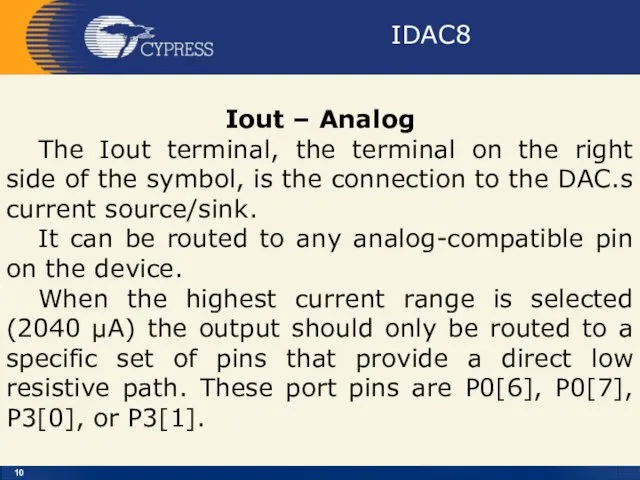
Iout – Analog
The Iout terminal, the terminal on the right
IDAC8
Iout – Analog
The Iout terminal, the terminal on the right
IDAC8
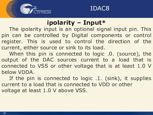
ipolarity – Input*
The ipolarity input is an optional signal input
IDAC8
ipolarity – Input*
The ipolarity input is an optional signal input
IDAC8
IDAC8
IDAC8
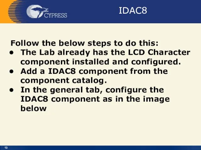
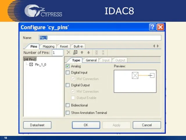
Follow the below steps to do this:
The Lab already has
IDAC8
Follow the below steps to do this:
The Lab already has
Creator
Creator
File – New - Projekt
File – New - Projekt
Empty PSoC 3 Design
Empty PSoC 3 Design
IDAC8
IDAC8
IDAC8
IDAC8
IDAC8
IDAC8
IDAC8
IDAC8
IDAC8
IDAC8
IDAC8
IDAC8
IDAC8
IDAC8
IDAC8
Overview:
Activate and use
the IDAC8 on the DVK board
and
IDAC8
Overview:
Activate and use
the IDAC8 on the DVK board
and
IDAC8
Зняти
вольт-амперну характеристику
напівпровідникового діода
IDAC8
Зняти
вольт-амперну характеристику
напівпровідникового діода
IDAC8
IDAC8
Приклади застосування
МК PSOC
На сайті фірми Cypress знаходиться більше 200 Application
Приклади застосування
МК PSOC
На сайті фірми Cypress знаходиться більше 200 Application
Похожие презентации
 Основи мікро- і наноелектроніки. МДН транзистори. (Лекція 9)
 Подготовка обучающихся 5-6 классов в освоению курсов Алгебра и Геометрия
 Умники и умницы
 Передвижная выставка фотохудожника Георгия Богословского Будь счастливым на чистой Земле!
 Колядки
 игра Копилка знаний
 Развитие микро- и наноэлектронных технологий
 Физические основы радиоэлектронных способов воздействия угроз на объекты
 Резервуарлар. Мұнай резервуарлары деп
 Легка промисловість України
 Көлік түрлері
 Аппараты воздушного охлаждения
 Великий пост
 урок в 9 классе Азотная кислота
 Септический шок
 Modern TV series are better than blockbuster films. Современные сериалы лучше блокбастеров
 Моя работа
 Теория брендинга. Модели бренд-образования
 Возрастная психология. Введение в возрастную психологию. Методическое сопровождение уроков психологии
 Технохимический контроль при производстве плодов кориандра
 Консультация для родителей: Речевое развитие детей 2 – 3 лет
 Атмосферное давление (презентация)
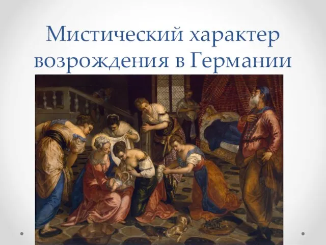 Мистический характер искусства возрождения в Германии
 Utilajul frigorific din sala de comerț
 Носители информации: краткая история
 Аква Ирендык
 краеведение Диск