NetCol5000-A 42 kW Air Cooled In-row Full-sized Variable-Frequency Precision Air Conditioner Training Slides--part 1 презентация
- NetCol5000-A 42 kW Air Cooled In-row Full-sized Variable-Frequency Precision Air Conditioner Training Slides--part 1

Содержание
- 2. Objectives Upon completion of this course, you will be able to learn the following information about
- 3. Contents
- 4. Contents
- 5. 1.1 Cooling Principle Cooling system conceptual diagram High temperature, high pressure, and liquid Liquid pipe needle
- 6. 1.1 Cooling Principle-Without a Low-Temperature Component 1 Basic Information
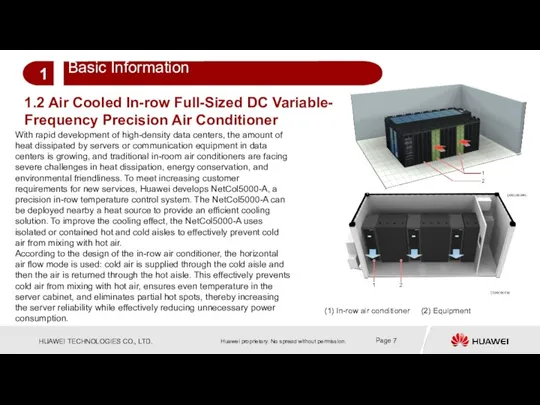
- 7. 1.2 Air Cooled In-row Full-Sized DC Variable- Frequency Precision Air Conditioner With rapid development of high-density
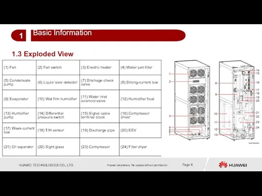
- 8. 1.3 Exploded View
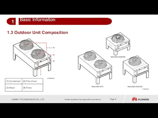
- 9. 1.3 Outdoor Unit Composition
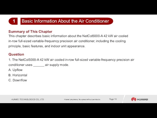
- 10. Summary of This Chapter This chapter describes basic information about the NetCol5000-A 42 kW air cooled
- 11. Contents
- 12. Works in an environment with an outdoor temperature ranging from –40 °C to +55 °C. Applies
- 13. When only one NetCol5000-A is running, the controller provides logic control for internal components to meet
- 14. 2.2 Indoor Unit Parameter Description
- 15. 2.3 Outdoor Unit Parameter Description
- 16. Cooling capacity Unit T1&T3 Power supply Pipe routing Condensate pump Heating & humidification Power system Model
- 17. Summary of This Chapter This chapter describes the main features of the NetCol5000-A 42 kW air
- 18. Features and Parameters 2 Main Components 3 Routine Maintenance 5 Parts Replacement and Troubleshooting 6 Installation
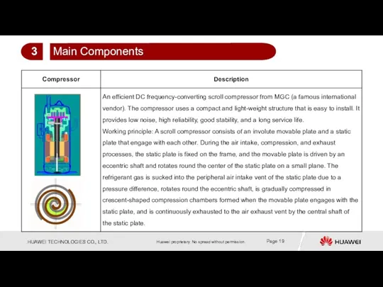
- 19. 3 Main Components
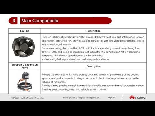
- 22. 3 Main Components
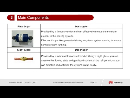
- 24. 3 Main Components
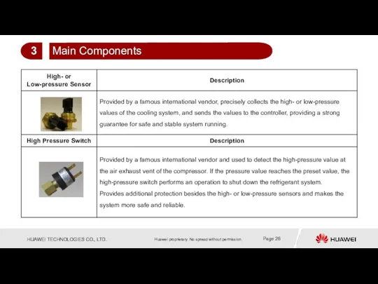
- 26. 3 Main Components
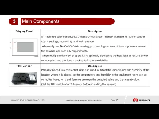
- 27. 3 Main Components
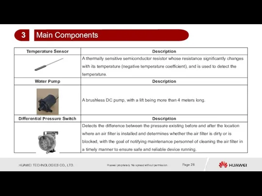
- 28. 3 Main Components
- 31. Summary of This Chapter This chapter describes the main components of the NetCol5000-A 42 kW air
- 32. Features and Parameters 2 Routine Maintenance 5 Parts Replacement and Troubleshooting 6 Main Components 3 Contents
- 33. 4.1 Installation Process Flowchart
- 34. 4.2 Preparing Materials-Installation Tools Indoor unit structure Installation tools
- 35. 4.2 Preparing Materials-Refrigerant R410A (Optional) Do not use low-quality refrigerant. Huawei is not responsible for any
- 36. The recommended refrigerant oil is MEL-32. You can purchase it from Huawei or purchase it by
- 37. 4.2 Preparing Materials-Oil Trap and Inverted Trap
- 38. Determine the total equivalent length of refrigerant pipes based on site requirements. Consider the bend resistance.
- 39. The water inlet pipe for the humidifier can be connected in two methods: Rigid pipe connection:
- 40. 4.2 Preparing Materials-Connecting the Drainpipe Drainpipes can be connected by using two methods: Routing pipes from
- 41. The figure shows the supports for the refrigerant and water pipes. Select supports based on the
- 42. 4.2 Preparing Materials-Cables
- 43. 4.2 Preparing Materials-Cables
- 44. The layout principles are as follows: If the outdoor unit is placed higher than the indoor
- 45. Transport a NetCol5000-A to a desired site. Unpack and accept the unit. Perform an air tightness
- 46. 12. Install an outdoor unit. In the case of a horizontal installation: a. Install the four
- 47. 16. Connect the drainpipe and water pipes. a. Drainpipe: Remove the drainpipe plug. Install the water
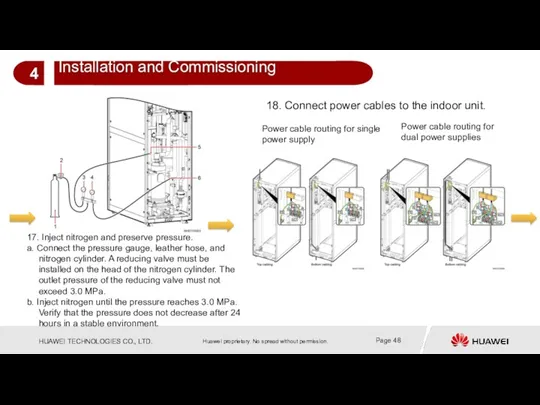
- 48. 17. Inject nitrogen and preserve pressure. a. Connect the pressure gauge, leather hose, and nitrogen cylinder.
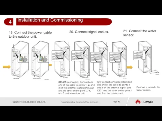
- 49. 19. Connect the power cable to the outdoor unit. 20. Connect signal cables. (RS485 connection) Connect
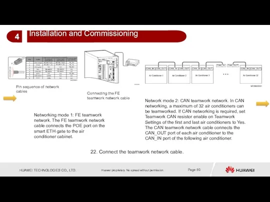
- 50. Network mode 2: CAN teamwork network. In CAN networking, a maximum of 32 air conditioners can
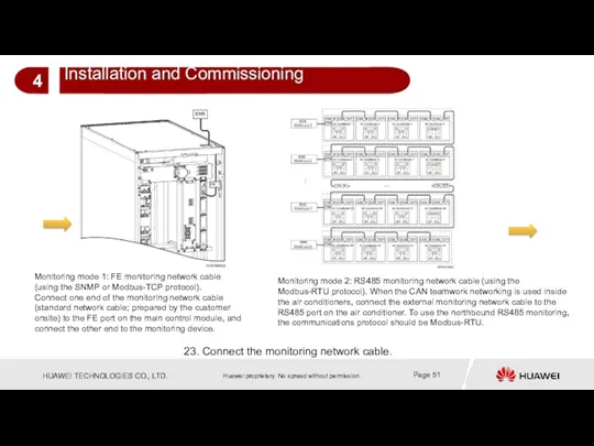
- 51. 23. Connect the monitoring network cable. Monitoring mode 2: RS485 monitoring network cable (using the Modbus-RTU
- 52. 25. Vacuumize the cooling system. 1. Connect the T/H sensors outside the cabinet and the T/H
- 53. 27. Prepare for power-on. Verify that the circuit breakers, cables, and water inlet and outlet pipes
- 54. Pipe Welding 4.5 Installation Precautions Before the welding, take measures to protect needle valves (discharge pipe
- 55. Foreign Matter Discharge for Pipes 4.5 Installation Precautions Foreign matter discharge for an air pipe (the
- 56. Vacuumizing 4.5 Installation Precautions After checking that the cooling system does not leak, vacuumize the cooling
- 57. 4.5 Installation Precautions Refrigerant Charging Remove the vacuum pump from the vacuumizing equipment, and replace the
- 58. Routing cables for an indoor unit with single power supply Routing cables for an indoor unit
- 59. Connecting pipes for the outdoor unit: Before welding pipes, take measures to protect nearby cables and
- 60. Note: The shaded parts in the figures are obstacles. The distances marked are the minimum distances
- 61. 4.5 Installation Precautions Power Cable Connection —Connecting Power Cables to an Outdoor Unit
- 62. Route the outdoor unit power cable through the cabinet cable hole to the L1, L2, L3,
- 63. Installing a PG connector Note: Tighten the PG connector securely. Otherwise, water may seep into the
- 64. (RS485 connection) Connect one end of the cable to points 1, 2, and 3 on the
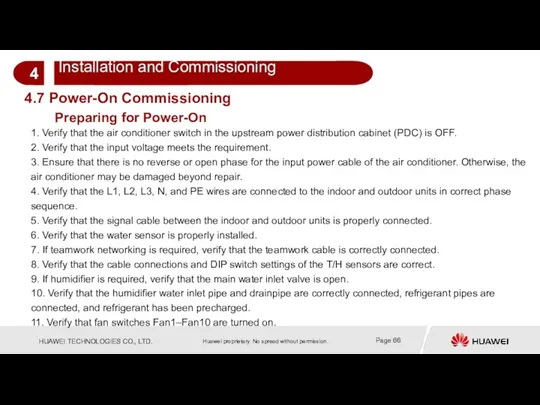
- 65. 4.6 Verifying the Installation
- 66. 1. Verify that the air conditioner switch in the upstream power distribution cabinet (PDC) is OFF.
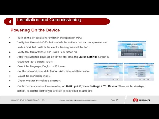
- 67. Powering On the Device Turn on the air conditioner switch in the upstream PDC. Verify that
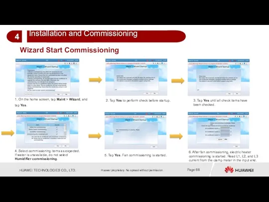
- 68. Wizard Start Commissioning 1. On the home screen, tap Maint > Wizard, and tap Yes. 2.
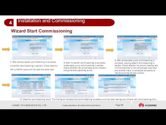
- 69. Wizard Start Commissioning 7. After electric heater commissioning is complete, humidifier commissioning is started. Check whether
- 70. Precautions for Wizard Startup 1. Ensure that refrigerant is fully charged before performing the wizard startup.
- 71. Check After Commissioning
- 72. Powering Off the Device Tap Shutdown on the LCD home screen. Switch off all switches in
- 73. Outputting Commissioning Report
- 74. Screen Description Start screen 7-inch true color touchscreen The standby screen becomes dark if no button
- 75. Screen Home screen The upper bar displays the status. The bar below the status bar displays
- 76. Alarms Alarm screen Querying active alarms Querying historical alarms Deleting historical alarms Screen for querying active
- 77. Screen for querying historical alarms A maximum of 500 historical alarms can be displayed. Historical alarms
- 78. Login Screen Logging in to Settings Before logging in to the Settings screen to configure the
- 79. Settings Settings screen 1. The User Settings screen allows you to configure the language, system time,
- 80. Maintenance Maintenance screen This screen consists of Diagnostic Mode, Log Maint, Performance Maintain, Sensor Adjust, Screen
- 81. About Help screen This screen displays the equipment model, manufacturer, monitoring device version, product version, and
- 82. 4.9 Screen (Outdoor Unit) Controller for NetCol500-A036 and NetCol500-A072 The following figure shows the screen, containing
- 83. Summary of This Chapter This chapter describes installation and commissioning for NetCol5000-A 42 kW air cooled
- 84. Contents
- 85. 5.1 Monthly Maintenance
- 87. 5.2 Semi-annual Maintenance
- 88. 5.3 Annual Maintenance
- 89. Summary of This Chapter This chapter describes routine maintenance for NetCol5000-A 42 kW air cooled in-row
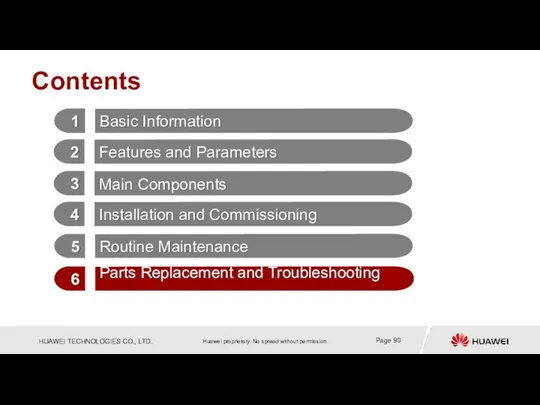
- 90. Contents
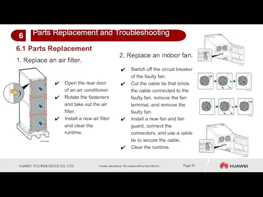
- 91. 6.1 Parts Replacement 1. Replace an air filter. Open the rear door of an air conditioner.
- 92. 3. Replace a differential pressure switch. Switch off the air conditioner circuit breaker in the PDC.
- 93. 4. Replace a compressor. Remove the compressor rack and then remove the compressor. Remove the crankcase
- 94. 4. Replace a compressor. Replace a compressor, and fix the compressor rack. Install angle valves and
- 95. 5. Replace the driver of a compressor. Switch off the upstream circuit breaker of the air
- 96. 6. Replace a filter dryer. Power off the air condition and switch off the compressor QF3
- 97. 7. Replace a liquid level detector. Turn off the air conditioner switch, open the front door,
- 98. 8. Replace an electric heater. On the controller home screen, tap Shutdown, and turn off the
- 99. 9. Replace an LCD. Tap Shutdown on the LCD home screen. Open the front door of
- 100. 10. Replace a PSU, a control module, or an auxiliary source module. Open the front door
- 101. 11. Uninstall an electric control box. On the controller home screen, tap Shutdown, and turn off
- 102. 12. Replace a condensate pump. On the controller home screen, tap Shutdown, and turn off the
- 103. 13. Replace a humidifier pump. On the controller home screen, tap Shutdown, and turn off the
- 104. 14. Replace a wet film humidifier. On the controller home screen, tap Shutdown, and turn off
- 105. 6.2 Exporting Fault Data You can export data in one-click mode or by configurations. With the
- 106. Tap Maint > USB Operations > Export on the home screen to enter the Select Path
- 107. To upgrade ACC V200R001C30B052 to ACC V200R001C30B053, perform the following steps: 1. Obtain the Huawei_ACC_V200R001C30B053.tar.gz package
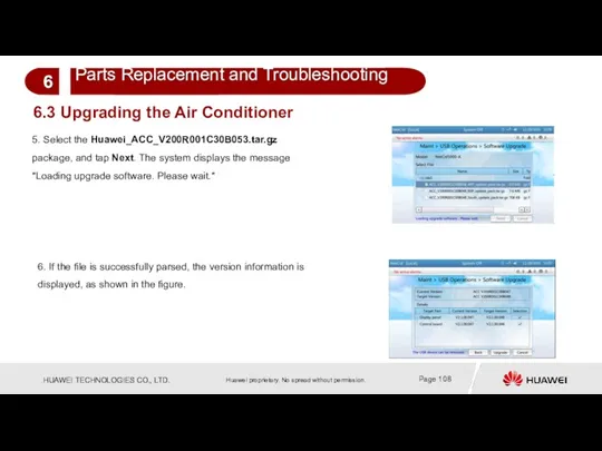
- 108. 5. Select the Huawei_ACC_V200R001C30B053.tar.gz package, and tap Next. The system displays the message "Loading upgrade software.
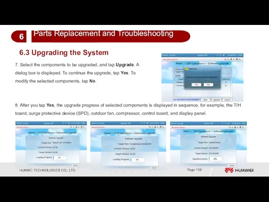
- 109. 7. Select the components to be upgraded, and tap Upgrade. A dialog box is displayed. To
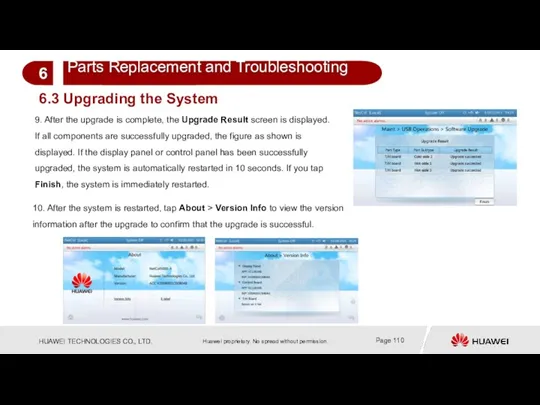
- 110. 9. After the upgrade is complete, the Upgrade Result screen is displayed. If all components are
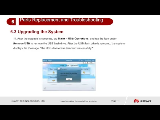
- 111. 11. After the upgrade is complete, tap Maint > USB Operations, and tap the icon under
- 112. 6.3 Common Alarm Handling
- 113. 6.3 Common Alarm Handling
- 114. 6.3 Common Alarm Handling
- 115. Alarms
- 116. Summary of This Chapter This chapter describes parts replacement and methods for exporting fault information of
- 118. Скачать презентацию
Objectives
Upon completion of this course, you will be able to learn
Objectives
Upon completion of this course, you will be able to learn
Contents
Contents
Contents
Contents
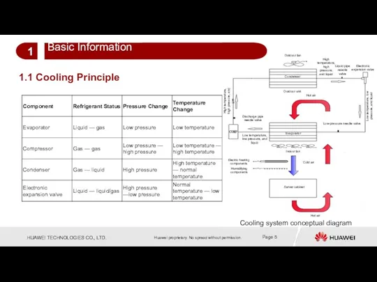
1.1 Cooling Principle
Cooling system conceptual diagram
High temperature, high pressure, and liquid
Liquid
1.1 Cooling Principle
Cooling system conceptual diagram
High temperature, high pressure, and liquid
Liquid
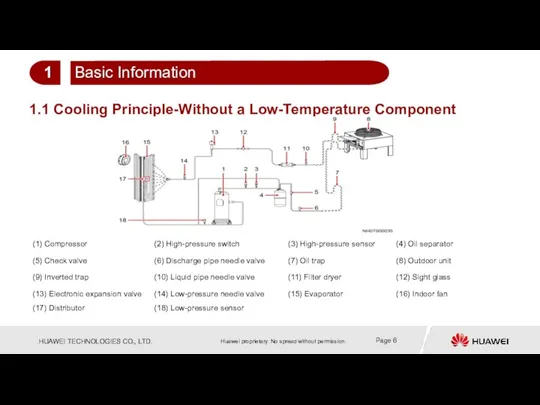
1.1 Cooling Principle-Without a Low-Temperature Component
1
Basic Information
1.1 Cooling Principle-Without a Low-Temperature Component
1
Basic Information
1.2 Air Cooled In-row Full-Sized DC Variable-
Frequency Precision Air Conditioner
With rapid
1.2 Air Cooled In-row Full-Sized DC Variable-
Frequency Precision Air Conditioner
With rapid
1.3 Exploded View
1.3 Exploded View
1.3 Outdoor Unit Composition
1.3 Outdoor Unit Composition
Summary of This Chapter
This chapter describes basic information about the NetCol5000-A
Summary of This Chapter
This chapter describes basic information about the NetCol5000-A
Contents
Contents
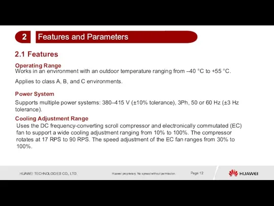
Works in an environment with an outdoor temperature ranging from –40
Works in an environment with an outdoor temperature ranging from –40
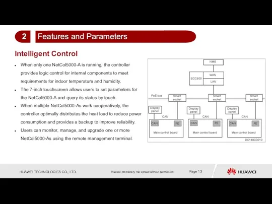
When only one NetCol5000-A is running, the controller provides logic control
When only one NetCol5000-A is running, the controller provides logic control
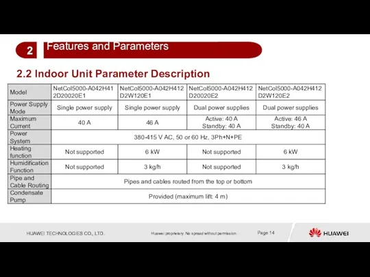
2.2 Indoor Unit Parameter Description
2.2 Indoor Unit Parameter Description
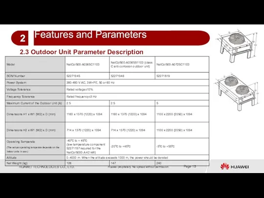
2.3 Outdoor Unit Parameter Description
2.3 Outdoor Unit Parameter Description
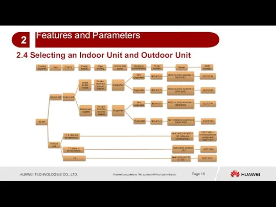
Cooling capacity
Unit
T1&T3
Power supply
Pipe routing
Condensate pump
Heating & humidification
Power system
Model
BOM number
42 kW
Indoor unit
Indoor
Cooling capacity
Unit
T1&T3
Power supply
Pipe routing
Condensate pump
Heating & humidification
Power system
Model
BOM number
42 kW
Indoor unit
Indoor
Summary of This Chapter
This chapter describes the main features of the
Summary of This Chapter
This chapter describes the main features of the
Features and Parameters
2
Main Components
3
Routine Maintenance
5
Parts Replacement and Troubleshooting
6
Installation and Commissioning
4
Basic Information
1
Contents
Features and Parameters
2
Main Components
3
Routine Maintenance
5
Parts Replacement and Troubleshooting
6
Installation and Commissioning
4
Basic Information
1
Contents
3
Main Components
3
Main Components


3
Main Components
3
Main Components

3
Main Components
3
Main Components

3
Main Components
3
Main Components
3
Main Components
3
Main Components
3
Main Components
3
Main Components


Summary of This Chapter
This chapter describes the main components of the
Summary of This Chapter
This chapter describes the main components of the
Features and Parameters
2
Routine Maintenance
5
Parts Replacement and Troubleshooting
6
Main Components
3
Contents
1
Basic Information
4
Installation and Commissioning
Features and Parameters
2
Routine Maintenance
5
Parts Replacement and Troubleshooting
6
Main Components
3
Contents
1
Basic Information
4
Installation and Commissioning
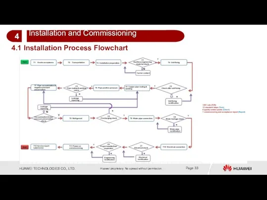
4.1 Installation Process Flowchart
4.1 Installation Process Flowchart
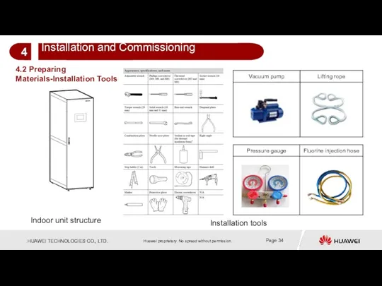
4.2 Preparing Materials-Installation Tools
Indoor unit structure
Installation tools
4.2 Preparing Materials-Installation Tools
Indoor unit structure
Installation tools
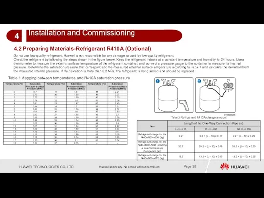
4.2 Preparing Materials-Refrigerant R410A (Optional)
Do not use low-quality refrigerant. Huawei is
4.2 Preparing Materials-Refrigerant R410A (Optional)
Do not use low-quality refrigerant. Huawei is
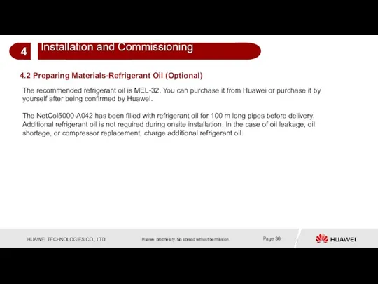
The recommended refrigerant oil is MEL-32. You can purchase it from
The recommended refrigerant oil is MEL-32. You can purchase it from
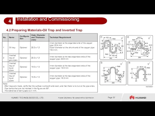
4.2 Preparing Materials-Oil Trap and Inverted Trap
4.2 Preparing Materials-Oil Trap and Inverted Trap
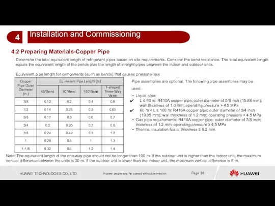
Determine the total equivalent length of refrigerant pipes based on site
Determine the total equivalent length of refrigerant pipes based on site
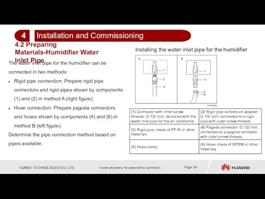
The water inlet pipe for the humidifier can be connected in
The water inlet pipe for the humidifier can be connected in
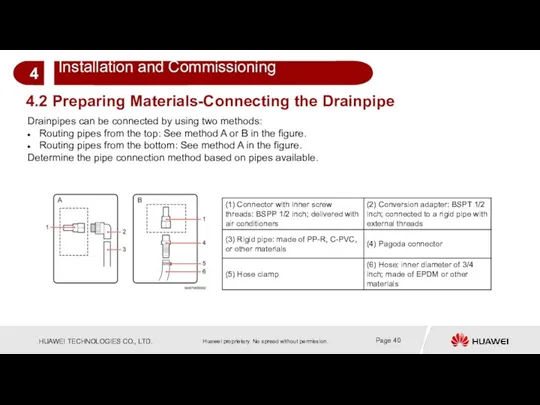
4.2 Preparing Materials-Connecting the Drainpipe
Drainpipes can be connected by using two
4.2 Preparing Materials-Connecting the Drainpipe
Drainpipes can be connected by using two
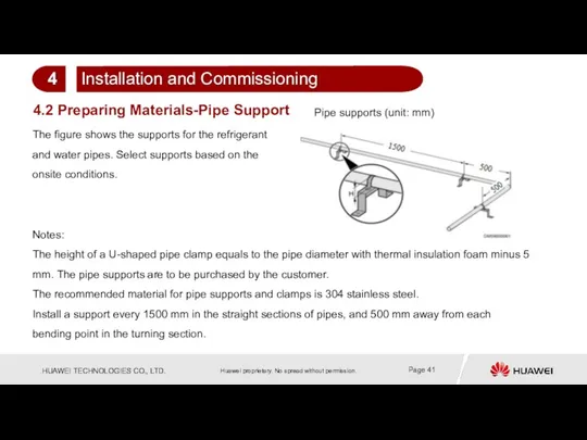
The figure shows the supports for the refrigerant and water pipes.
The figure shows the supports for the refrigerant and water pipes.
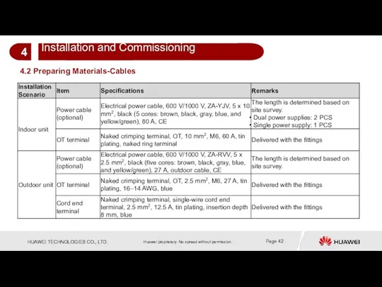
4.2 Preparing Materials-Cables
4.2 Preparing Materials-Cables
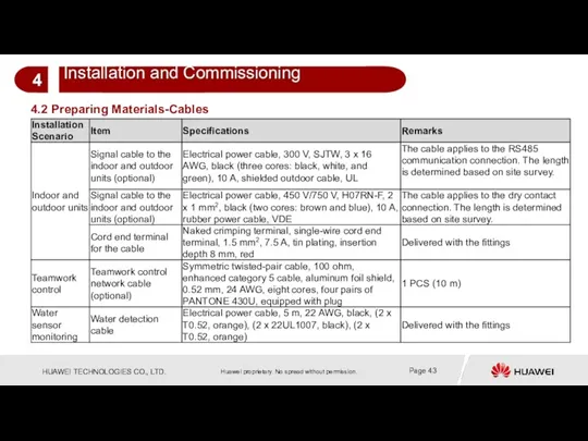
4.2 Preparing Materials-Cables
4.2 Preparing Materials-Cables
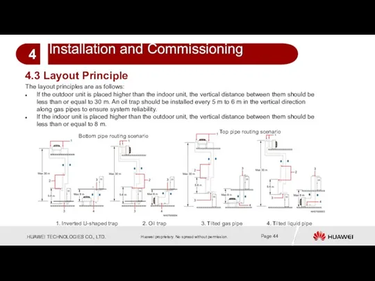
The layout principles are as follows:
If the outdoor unit is placed
The layout principles are as follows:
If the outdoor unit is placed
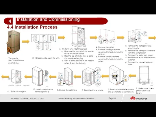
Transport a NetCol5000-A to a desired site.
Unpack and accept the unit.
Perform
Transport a NetCol5000-A to a desired site.
Unpack and accept the unit.
Perform
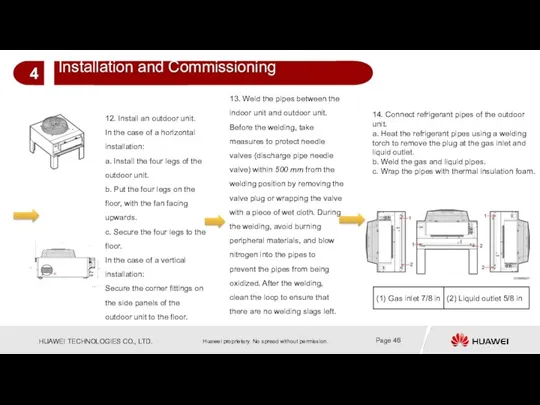
12. Install an outdoor unit.
In the case of a horizontal installation:
a.
12. Install an outdoor unit.
In the case of a horizontal installation:
a.
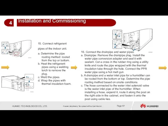
16. Connect the drainpipe and water pipes.
a. Drainpipe: Remove the drainpipe
16. Connect the drainpipe and water pipes.
a. Drainpipe: Remove the drainpipe
17. Inject nitrogen and preserve pressure.
a. Connect the pressure gauge, leather
17. Inject nitrogen and preserve pressure.
a. Connect the pressure gauge, leather
19. Connect the power cable to the outdoor unit.
20. Connect signal
19. Connect the power cable to the outdoor unit.
20. Connect signal
Network mode 2: CAN teamwork network. In CAN networking, a maximum
Network mode 2: CAN teamwork network. In CAN networking, a maximum
23. Connect the monitoring network cable.
Monitoring mode 2: RS485 monitoring network
23. Connect the monitoring network cable.
Monitoring mode 2: RS485 monitoring network
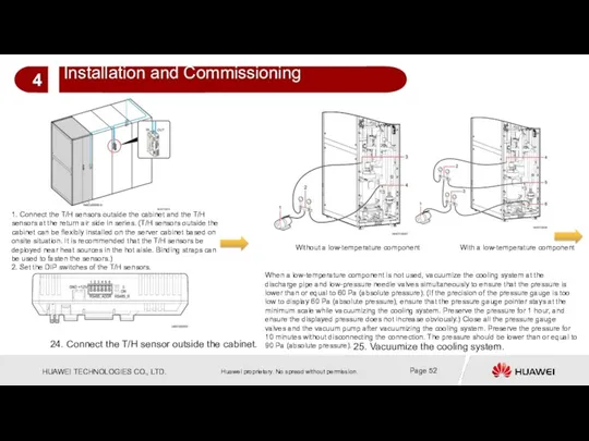
25. Vacuumize the cooling system.
1. Connect the T/H sensors outside the
25. Vacuumize the cooling system.
1. Connect the T/H sensors outside the
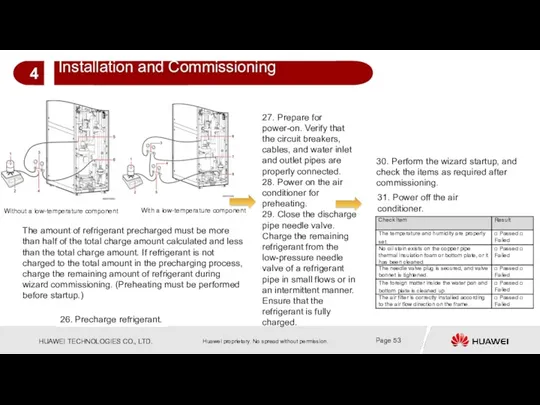
27. Prepare for power-on. Verify that the circuit breakers, cables, and
27. Prepare for power-on. Verify that the circuit breakers, cables, and
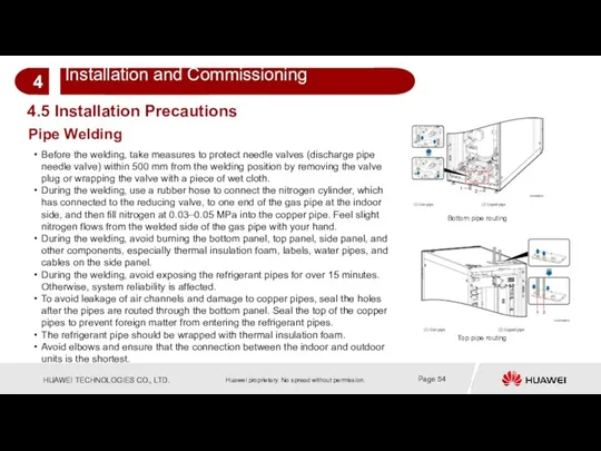
Pipe Welding
4.5 Installation Precautions
Before the welding, take measures to protect needle
Pipe Welding
4.5 Installation Precautions
Before the welding, take measures to protect needle

Foreign Matter Discharge for Pipes
4.5 Installation Precautions
Foreign matter discharge for an
Foreign Matter Discharge for Pipes
4.5 Installation Precautions
Foreign matter discharge for an
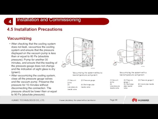
Vacuumizing
4.5 Installation Precautions
After checking that the cooling system does not leak,
Vacuumizing
4.5 Installation Precautions
After checking that the cooling system does not leak,
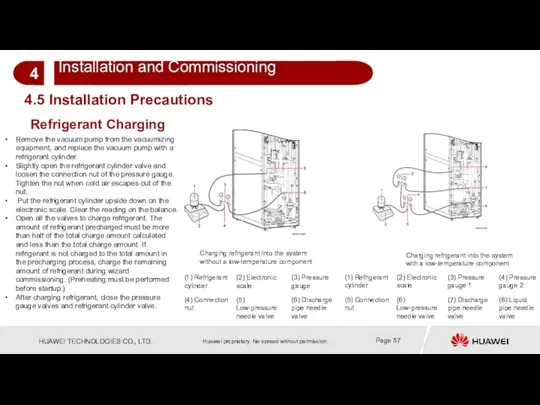
4.5 Installation Precautions
Refrigerant Charging
Remove the vacuum pump from the vacuumizing equipment,
4.5 Installation Precautions
Refrigerant Charging
Remove the vacuum pump from the vacuumizing equipment,
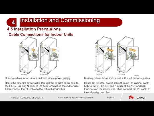
Routing cables for an indoor unit with single power supply
Routing cables
Routing cables for an indoor unit with single power supply
Routing cables
Connecting pipes for the outdoor unit:
Before welding pipes, take measures
Connecting pipes for the outdoor unit:
Before welding pipes, take measures

Note:
The shaded parts in the figures are obstacles. The distances marked
Note:
The shaded parts in the figures are obstacles. The distances marked
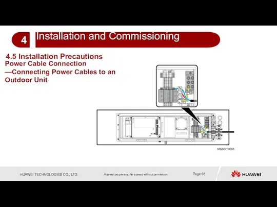
4.5 Installation Precautions
Power Cable Connection —Connecting Power Cables to an Outdoor
4.5 Installation Precautions
Power Cable Connection —Connecting Power Cables to an Outdoor
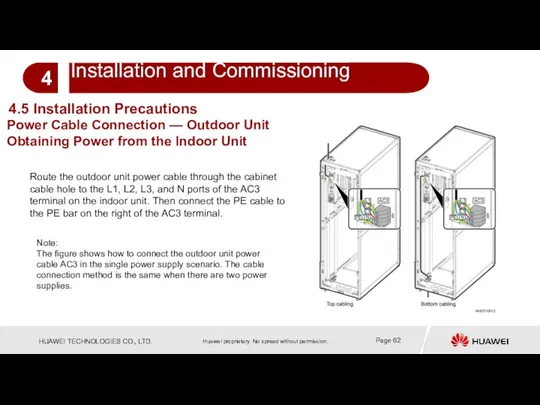
Route the outdoor unit power cable through the cabinet cable hole
Route the outdoor unit power cable through the cabinet cable hole
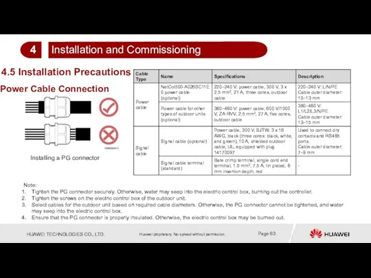
Installing a PG connector
Note:
Tighten the PG connector securely. Otherwise, water may
Installing a PG connector
Note:
Tighten the PG connector securely. Otherwise, water may
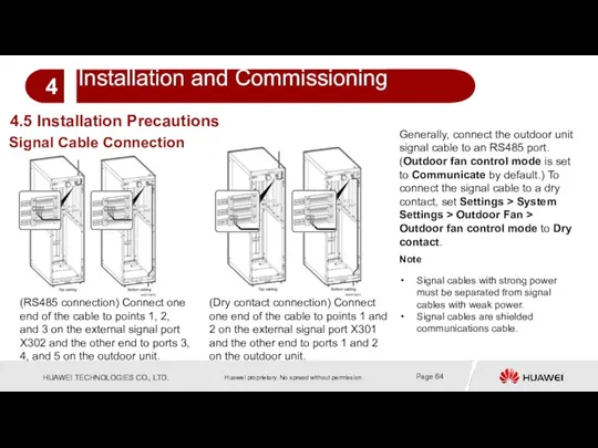
(RS485 connection) Connect one end of the cable to points 1,
(RS485 connection) Connect one end of the cable to points 1,
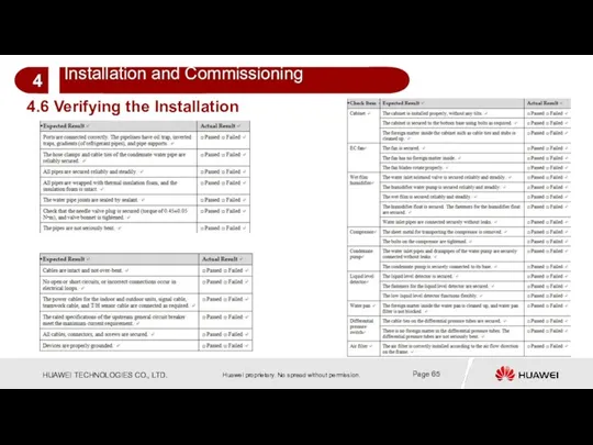
4.6 Verifying the Installation
4.6 Verifying the Installation
1. Verify that the air conditioner switch in the upstream power
Powering On the Device
Turn on the air conditioner switch in the
Powering On the Device
Turn on the air conditioner switch in the
Wizard Start Commissioning
1. On the home screen, tap Maint >
Wizard Start Commissioning
1. On the home screen, tap Maint >
Wizard Start Commissioning
7. After electric heater commissioning is complete, humidifier commissioning
Wizard Start Commissioning
7. After electric heater commissioning is complete, humidifier commissioning
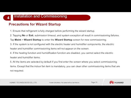
Precautions for Wizard Startup
1. Ensure that refrigerant is fully charged before
Precautions for Wizard Startup
1. Ensure that refrigerant is fully charged before
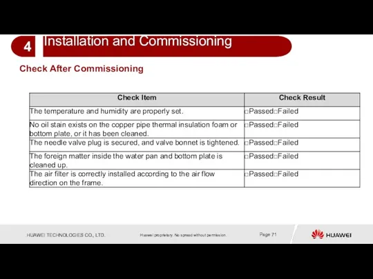
Check After Commissioning
Check After Commissioning
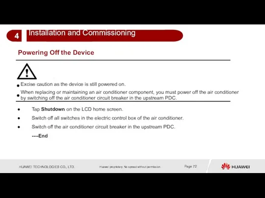
Powering Off the Device
Tap Shutdown on the LCD home screen.
Switch off
Powering Off the Device
Tap Shutdown on the LCD home screen.
Switch off
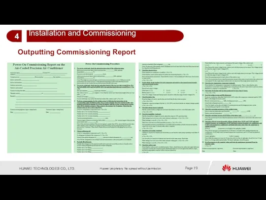
Outputting Commissioning Report
Outputting Commissioning Report
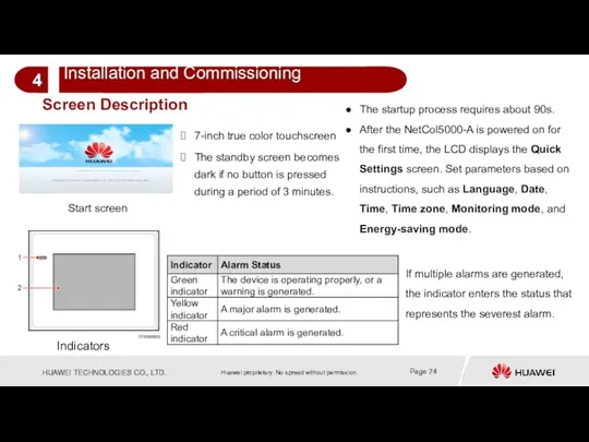
Screen Description
Start screen
7-inch true color touchscreen
The standby screen becomes dark if
Screen Description
Start screen
7-inch true color touchscreen
The standby screen becomes dark if
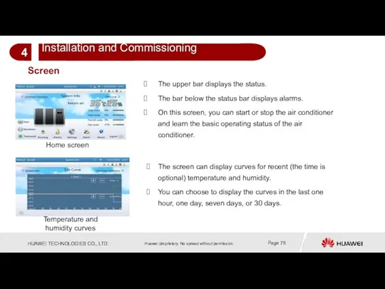
Screen
Home screen
The upper bar displays the status.
The bar below the status
Screen
Home screen
The upper bar displays the status.
The bar below the status
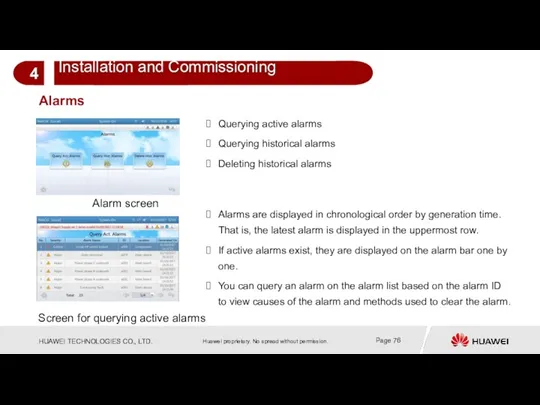
Alarms
Alarm screen
Querying active alarms
Querying historical alarms
Deleting historical alarms
Screen for querying active
Alarms
Alarm screen
Querying active alarms
Querying historical alarms
Deleting historical alarms
Screen for querying active
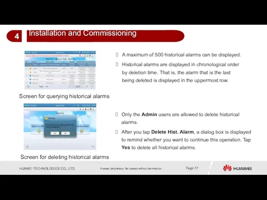
Screen for querying historical alarms
A maximum of 500 historical alarms can
Screen for querying historical alarms
A maximum of 500 historical alarms can
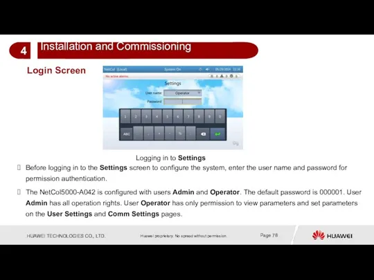
Login Screen
Logging in to Settings
Before logging in to the Settings screen
Login Screen
Logging in to Settings
Before logging in to the Settings screen
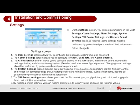
Settings
Settings screen
1. The User Settings screen allows you to configure the
Settings
Settings screen
1. The User Settings screen allows you to configure the
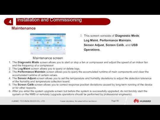
Maintenance
Maintenance screen
This screen consists of Diagnostic Mode, Log Maint, Performance Maintain,
Maintenance
Maintenance screen
This screen consists of Diagnostic Mode, Log Maint, Performance Maintain,
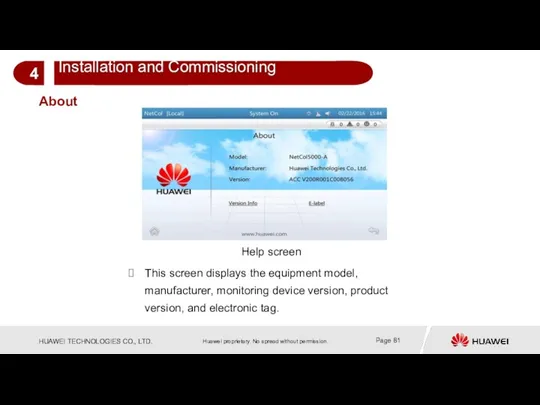
About
Help screen
This screen displays the equipment model, manufacturer, monitoring device version,
About
Help screen
This screen displays the equipment model, manufacturer, monitoring device version,
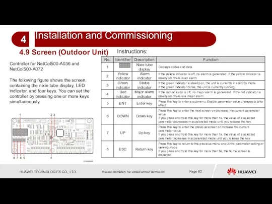
4.9 Screen (Outdoor Unit)
Controller for NetCol500-A036 and NetCol500-A072
The following figure shows
4.9 Screen (Outdoor Unit)
Controller for NetCol500-A036 and NetCol500-A072
The following figure shows

Summary of This Chapter
This chapter describes installation and commissioning for NetCol5000-A
Summary of This Chapter
This chapter describes installation and commissioning for NetCol5000-A
Contents
Contents
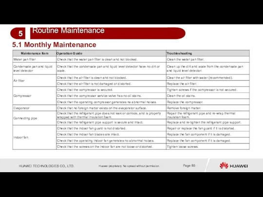
5.1 Monthly Maintenance
5.1 Monthly Maintenance

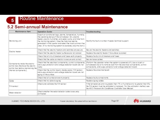
5.2 Semi-annual Maintenance
5.2 Semi-annual Maintenance
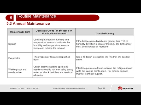
5.3 Annual Maintenance
5.3 Annual Maintenance
Summary of This Chapter
This chapter describes routine maintenance for NetCol5000-A 42
Summary of This Chapter
This chapter describes routine maintenance for NetCol5000-A 42
Contents
Contents
6.1 Parts Replacement
1. Replace an air filter.
Open the rear door of
6.1 Parts Replacement
1. Replace an air filter.
Open the rear door of
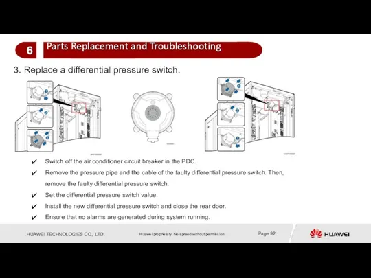
3. Replace a differential pressure switch.
Switch off the air conditioner circuit
3. Replace a differential pressure switch.
Switch off the air conditioner circuit
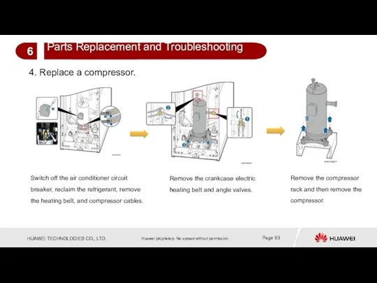
4. Replace a compressor.
Remove the compressor rack and then remove the
4. Replace a compressor.
Remove the compressor rack and then remove the
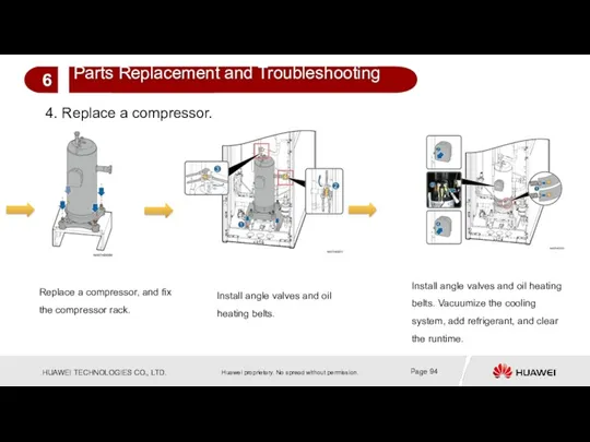
4. Replace a compressor.
Replace a compressor, and fix the compressor rack.
Install
4. Replace a compressor.
Replace a compressor, and fix the compressor rack.
Install
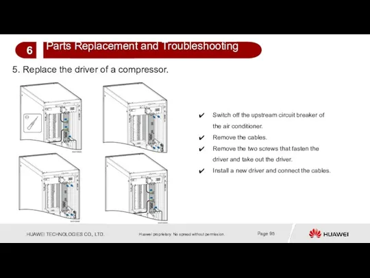
5. Replace the driver of a compressor.
Switch off the upstream circuit
5. Replace the driver of a compressor.
Switch off the upstream circuit
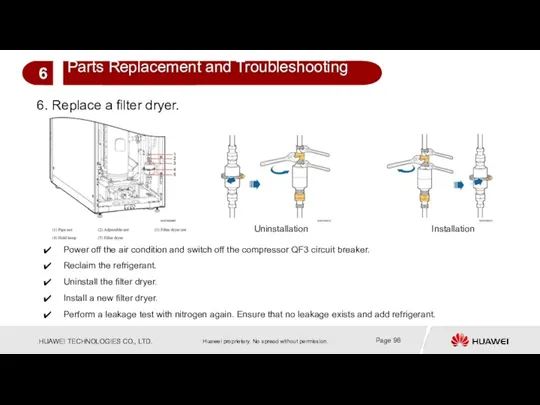
6. Replace a filter dryer.
Power off the air condition and switch
6. Replace a filter dryer.
Power off the air condition and switch
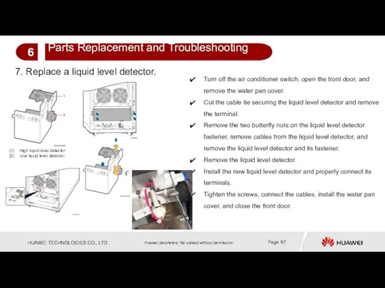
7. Replace a liquid level detector.
Turn off the air conditioner switch,
7. Replace a liquid level detector.
Turn off the air conditioner switch,
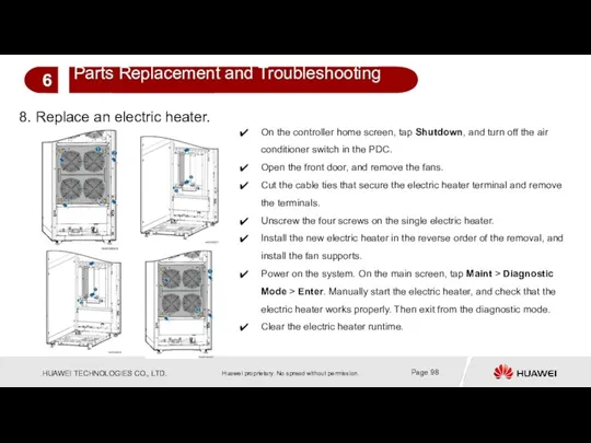
8. Replace an electric heater.
On the controller home screen, tap
8. Replace an electric heater.
On the controller home screen, tap
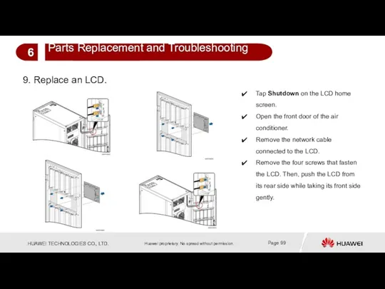
9. Replace an LCD.
Tap Shutdown on the LCD home screen.
Open the
9. Replace an LCD.
Tap Shutdown on the LCD home screen.
Open the
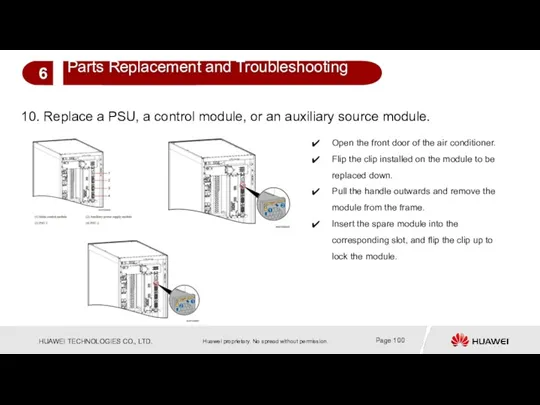
10. Replace a PSU, a control module, or an auxiliary source
10. Replace a PSU, a control module, or an auxiliary source
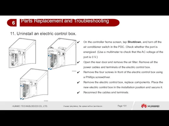
11. Uninstall an electric control box.
On the controller home screen, tap
11. Uninstall an electric control box.
On the controller home screen, tap
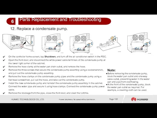
12. Replace a condensate pump.
On the controller home screen, tap
12. Replace a condensate pump.
On the controller home screen, tap
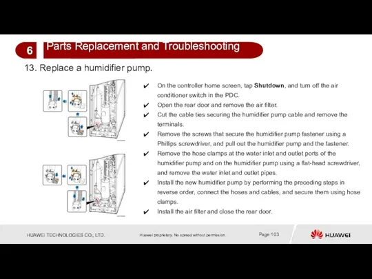
13. Replace a humidifier pump.
On the controller home screen, tap
13. Replace a humidifier pump.
On the controller home screen, tap
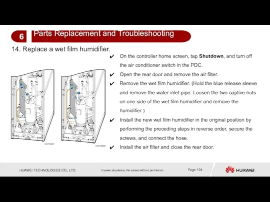
14. Replace a wet film humidifier.
On the controller home screen,
14. Replace a wet film humidifier.
On the controller home screen,
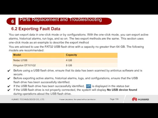
6.2 Exporting Fault Data
You can export data in one-click mode or
6.2 Exporting Fault Data
You can export data in one-click mode or
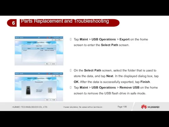
Tap Maint > USB Operations > Export on the home screen
Tap Maint > USB Operations > Export on the home screen
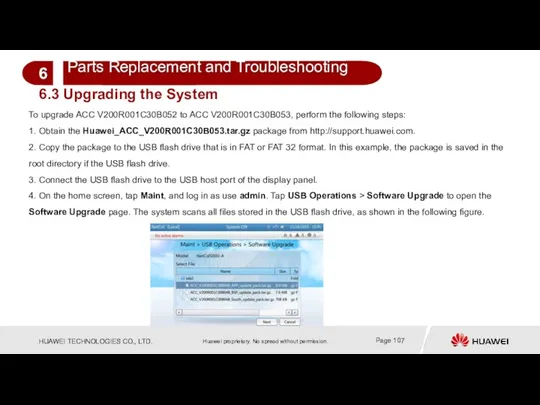
To upgrade ACC V200R001C30B052 to ACC V200R001C30B053, perform the following steps:
1.
To upgrade ACC V200R001C30B052 to ACC V200R001C30B053, perform the following steps:
1.
5. Select the Huawei_ACC_V200R001C30B053.tar.gz package, and tap Next. The system displays
5. Select the Huawei_ACC_V200R001C30B053.tar.gz package, and tap Next. The system displays
7. Select the components to be upgraded, and tap Upgrade. A
7. Select the components to be upgraded, and tap Upgrade. A
9. After the upgrade is complete, the Upgrade Result screen is
9. After the upgrade is complete, the Upgrade Result screen is
11. After the upgrade is complete, tap Maint > USB Operations,
11. After the upgrade is complete, tap Maint > USB Operations,
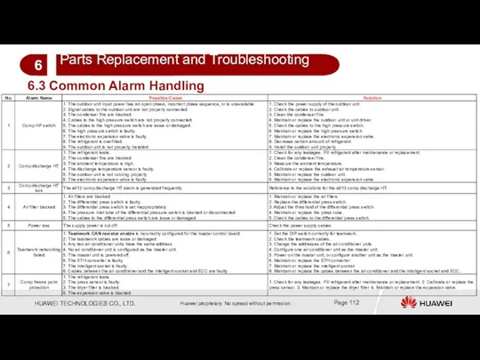
6.3 Common Alarm Handling
6.3 Common Alarm Handling
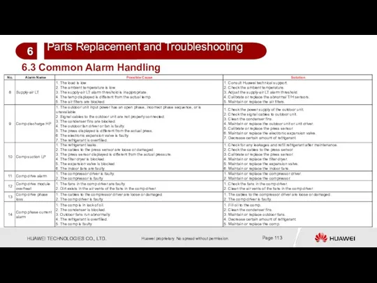
6.3 Common Alarm Handling
6.3 Common Alarm Handling
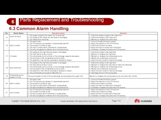
6.3 Common Alarm Handling
6.3 Common Alarm Handling
Alarms
Alarms
Summary of This Chapter
This chapter describes parts replacement and methods for
Summary of This Chapter
This chapter describes parts replacement and methods for
 Основа методики самостоятельных занятий физическими упражнениями
 Свет и цвет в фотографии
 Родительское собрание: Как воспитать уверенность ребёнка в себе
 Основные задачи токсикологической химии в аналитической диагностике наркотических и психотропных веществ (Продолжение)
 Photo description
 Изготовление доски для разделки рыбы
 Понятие формы. Многообразие форм окружающего мира
 Презентация Артикуляционная гимнастика для детей дошкольного возраста.
 Евроатлантическая цивилизация во второй половине 20 века
 Целевые ориентиры в работе учителя-логопеда
 Россия в эпоху правления Николая I (1825-1855)
 Пролапс тазовых органов: причины, симптомы, диагностика и лечение
 Наше Знамя Победы
 Профессиональная жизнь АТК КазАТК
 Интернет в жизни старшеклассника: за или против
 Образовательное проектирование как механизм управления
 Computer systems. Programming paradigms. Systems life cycle
 Лютеранство. Филипп Меланхтон (1497- 1560)
 История развития вычислительной техники
 Статические структуры данных. (Тема 2)
 Основні типи невпорядкованості напівпровідникових кристалів. (Лекція 1)
 ВЗАИМОДЕЙСТВИЕ ШКОЛЫ И СЕМЬИ В ДУХОВНО-НРАВСТВЕННОМ ВОСПИТАНИИ МЛАДШЕГО ШКОЛЬНИКА
 Слово. Повторение (2 класс)
 Конструктивное взаимодействие
 Стиль как визуальный язык
 Профессиональное обучение в системе непрерывного образования
 Математика - царица всех наук.КВН. 6 класс
 графические упражнения