- Networking Basics

Содержание
- 2. Agenda ● UDP vs TCP (usage in PortaSwitch) ● Routing (static, dynamic, gateways) ● Bonding (overview,
- 3. UDP vs TCP (usage in PortaSwitch)
- 5. OSI Encapsulation
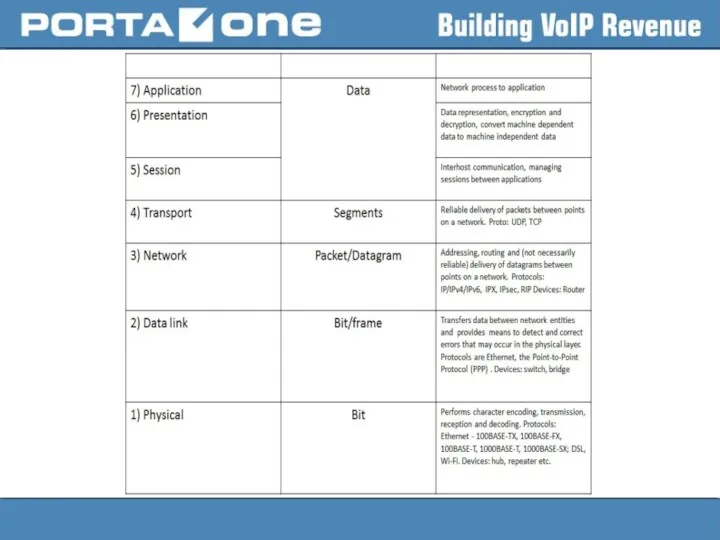
- 6. OSI (Open Source Interconnection) 7 Layer Model
- 7. OSI Model vs TCP/IP Model
- 8. TCP (Transport Control Protocol) ● is a connection-oriented transport layer protocol ● provides reliable full-duplex data
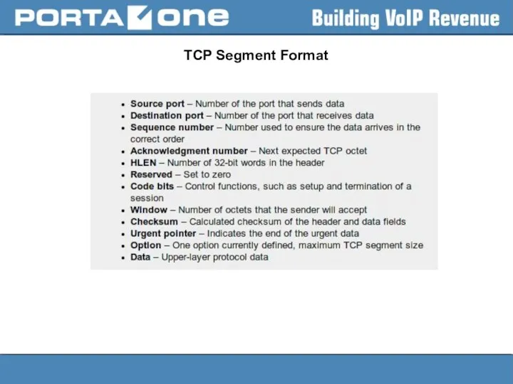
- 9. TCP Segment Format
- 10. TCP Segment Format
- 11. TCP session initiation
- 12. Well-known services that use TCP - FTP (20/TCP); SSH (22/TCP); Telnet (23/TCP); SMTP (25/TCP); HTTP (80/TCP);
- 13. UDP (User Datagram Protocol) ● is a simple protocol that exchanges datagrams without guaranteed delivery ●
- 14. Well-known services that use UDP DNS (53/UDP); NTP (123/UDP); Online gaming; Video streaming services; RTP; SIP;
- 15. UDP and TCP in PortaSwitch PortaBilling Master server
- 16. PortaBilling Web server
- 17. PortaSIP Cluster
- 18. Routing (static, dynamic, gateways) Routing is the process of selecting a path for traffic in a
- 19. Routers A router is a networking device that forwards data packets between computer networks. A router
- 20. Routing table Routing table is a data table stored in a router or a networked computer
- 21. Linux PC operating as a Router ● allows a PC on Linux OS to receive packets
- 22. Policy Based Routing Usually, route selection is based completely on the destination address using longest prefix
- 23. Route Selection Kernel route search order is: ● first in the routing cache ● then in
- 24. Using IP utility Display IP addresses configuration: > ip a | grep -A2 "eno[1-2]: " 2:
- 25. Using IP utility Display routing cache: > ip route show cache Display routing cache: > ip
- 26. Using IP utility Check what route will be used to destination: ip route get to >
- 27. Network Config Files ● are located in are located in the /etc/sysconfig/network-scripts/ directory ● three categories
- 28. Network Configuration Files /etc/hosts – contains list of host names that cannot or shouldn’t be resolved
- 29. Network Configuration Files Saving static routes in file to survive server reboot: > cat /etc/sysconfig/network-scripts/route-eno2 192.168.0.0/16
- 30. Why we should use command ‘ip’ Let’s check routing table using netstat –nr and route –n
- 31. Why we should use command ‘ip’ And now the same with “ip route show” > ip
- 32. Channel bonding Channel bonding enables two or more network interfaces to act as one, simultaneously increasing
- 33. Bonding mode mode= Allows specifies the bonding policy. The can be one of: balance-rr or 0
- 34. Bonding mode 802.3ad or 4 — Sets an IEEE 802.3ad dynamic link aggregation policy. Creates aggregation
- 35. Active-backup mode hint For active-backup mode, Linux kernel sets the same MAC address for both enslavedinterfaces
- 36. Manual configuration of channel bonding 1) Make sure that bonding kernel module is loaded (use lsmod).
- 37. Manual configuration of channel bonding 3) Add the MASTER and SLAVE directives to their configuration files
- 38. Manual configuration of channel bonding bond0 Link encap:Ethernet HWaddr D4:AE:52:BA:53:CF inet addr:83.245.1.152 Bcast:83.245.1.191 Mask:255.255.255.192 inet6 addr:
- 39. Useful SYSFS commands To view all existing bonds, even if they are not up: > cat
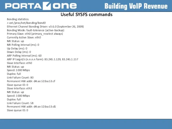
- 40. Useful SYSFS commands Bonding statistics: > cat /proc/net/bonding/bond0 Ethernet Channel Bonding Driver: v3.6.0 (September 26, 2009)
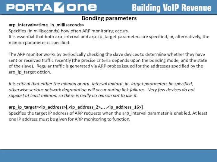
- 41. Bonding parameters arp_interval= Specifies (in milliseconds) how often ARP monitoring occurs. It is essential that both
- 42. Bonding parameters downdelay= Specifies (in milliseconds) how long to wait after link failure before disabling the
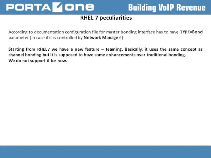
- 43. RHEL 7 peculiarities According to documentation configuration file for master bonding interface has to have TYPE=Bond
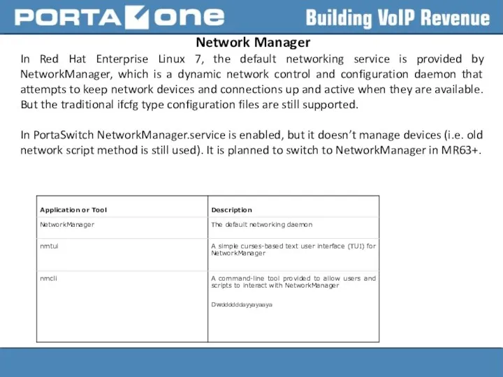
- 44. Network Manager In Red Hat Enterprise Linux 7, the default networking service is provided by NetworkManager,
- 45. Terms of Network Manager NM operates with the following terms: Connection and Device Device represents physical
- 46. Using nmcli to manipulate with networking NetworkManager can configure network aliases, IP addresses, static routes, DNS
- 47. Using nmcli to manipulate with networking Activate connection: nmcli connection up Shutdown connection: nmcli con down
- 48. How to disable Network Manager Add option “NM_CONTROLLED=NO” to /etc/sysconfig/network-scripts/ifcfg- scripts. After that nmcli connection reload
- 50. Скачать презентацию
Agenda
● UDP vs TCP (usage in PortaSwitch)
● Routing (static,
Agenda
● UDP vs TCP (usage in PortaSwitch)
● Routing (static,
UDP vs TCP (usage in PortaSwitch)
UDP vs TCP (usage in PortaSwitch)
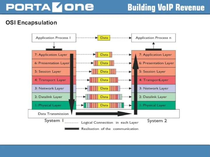
OSI Encapsulation
OSI Encapsulation
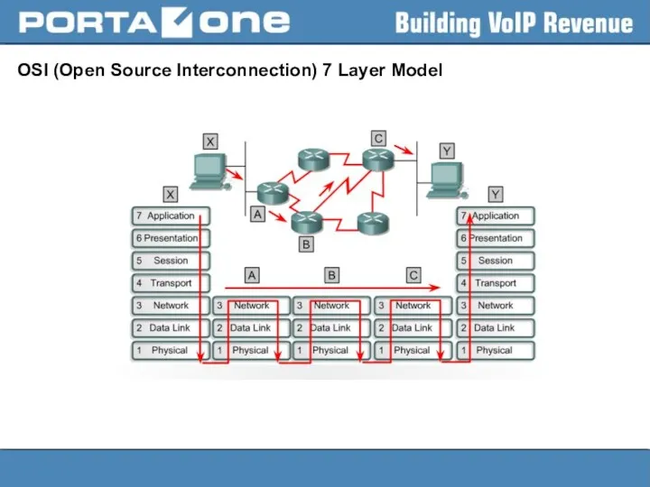
OSI (Open Source Interconnection) 7 Layer Model
OSI (Open Source Interconnection) 7 Layer Model
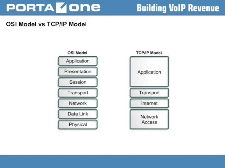
OSI Model vs TCP/IP Model
OSI Model vs TCP/IP Model
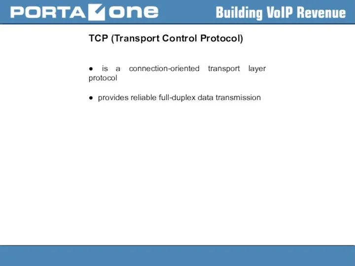
TCP (Transport Control Protocol)
● is a connection-oriented transport layer protocol
● provides
TCP (Transport Control Protocol)
● is a connection-oriented transport layer protocol
● provides
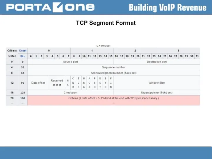
TCP Segment Format
TCP Segment Format
TCP Segment Format
TCP Segment Format
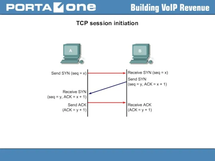
TCP session initiation
TCP session initiation
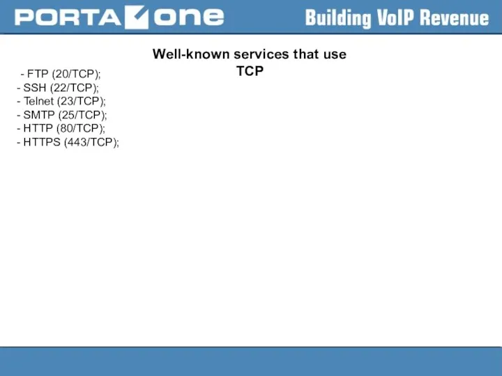
Well-known services that use TCP
- FTP (20/TCP);
SSH (22/TCP);
Telnet (23/TCP);
Well-known services that use TCP
- FTP (20/TCP);
SSH (22/TCP);
Telnet (23/TCP);
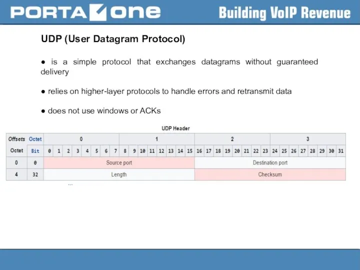
UDP (User Datagram Protocol)
● is a simple protocol that exchanges datagrams
UDP (User Datagram Protocol)
● is a simple protocol that exchanges datagrams
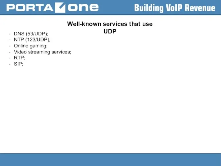
Well-known services that use UDP
DNS (53/UDP);
NTP (123/UDP);
Online gaming;
Video streaming services;
RTP;
SIP;
Well-known services that use UDP
DNS (53/UDP);
NTP (123/UDP);
Online gaming;
Video streaming services;
RTP;
SIP;
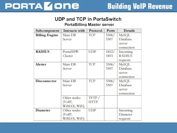
UDP and TCP in PortaSwitch
PortaBilling Master server
UDP and TCP in PortaSwitch
PortaBilling Master server
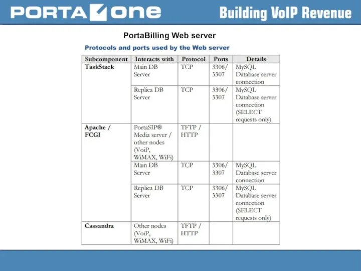
PortaBilling Web server
PortaBilling Web server
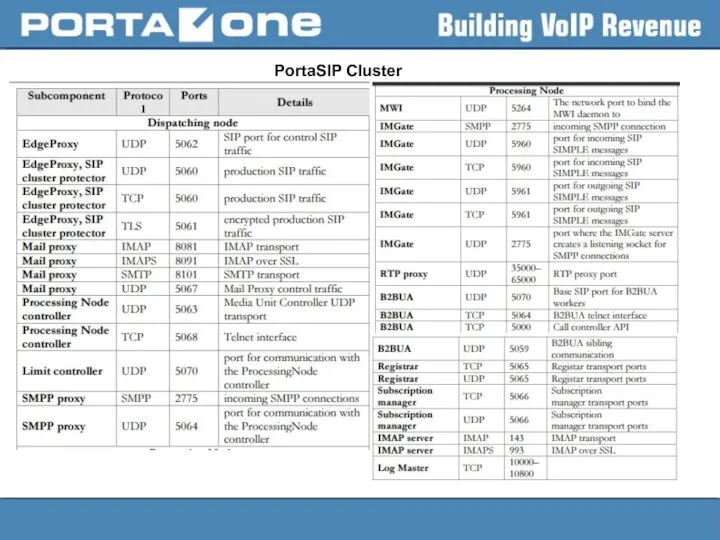
PortaSIP Cluster
PortaSIP Cluster
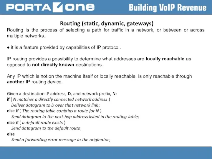
Routing (static, dynamic, gateways)
Routing is the process of selecting a
Routing (static, dynamic, gateways)
Routing is the process of selecting a
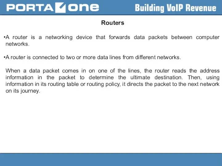
Routers
A router is a networking device that forwards data packets between
Routers
A router is a networking device that forwards data packets between
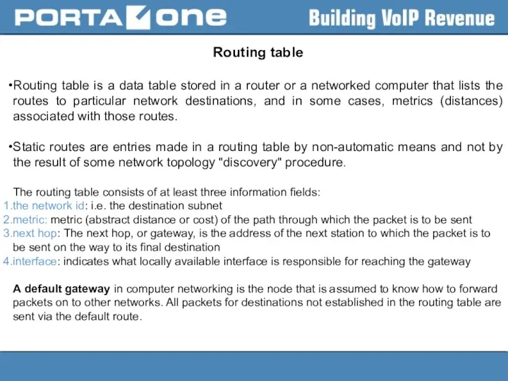
Routing table
Routing table is a data table stored in a router
Routing table
Routing table is a data table stored in a router
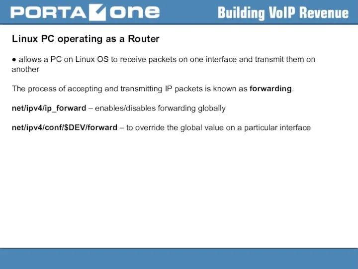
Linux PC operating as a Router
● allows a PC on Linux
Linux PC operating as a Router
● allows a PC on Linux
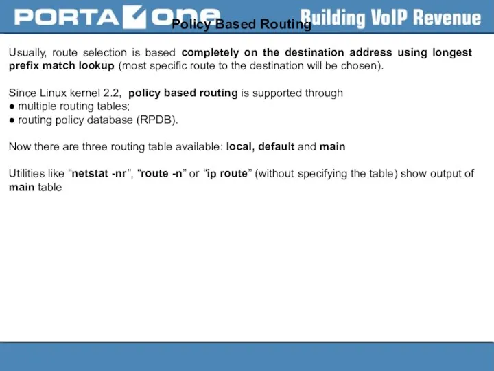
Policy Based Routing
Usually, route selection is based completely on the destination
Policy Based Routing
Usually, route selection is based completely on the destination
Route Selection
Kernel route search order is:
● first in the routing cache
●
Route Selection
Kernel route search order is:
● first in the routing cache
●
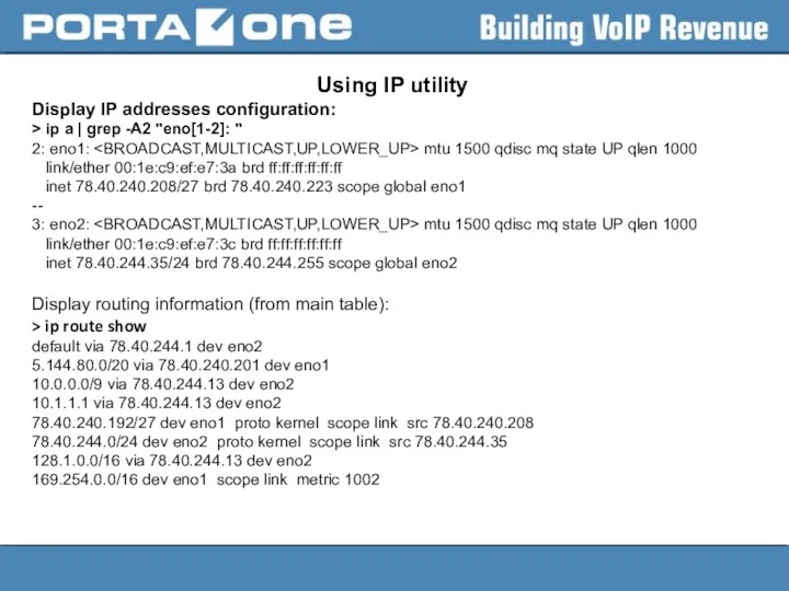
Using IP utility
Display IP addresses configuration:
> ip a | grep
Using IP utility
Display IP addresses configuration:
> ip a | grep
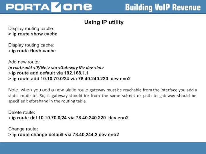
Using IP utility
Display routing cache:
> ip route show cache
Display routing
Using IP utility
Display routing cache:
> ip route show cache
Display routing
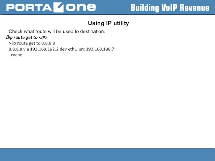
Using IP utility
Check what route will be used to destination:
ip
Using IP utility
Check what route will be used to destination:
ip
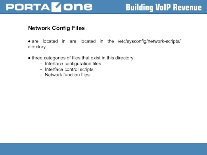
Network Config Files
● are located in are located in the /etc/sysconfig/network-scripts/ directory
● three
● are located in are located in the /etc/sysconfig/network-scripts/ directory
● three
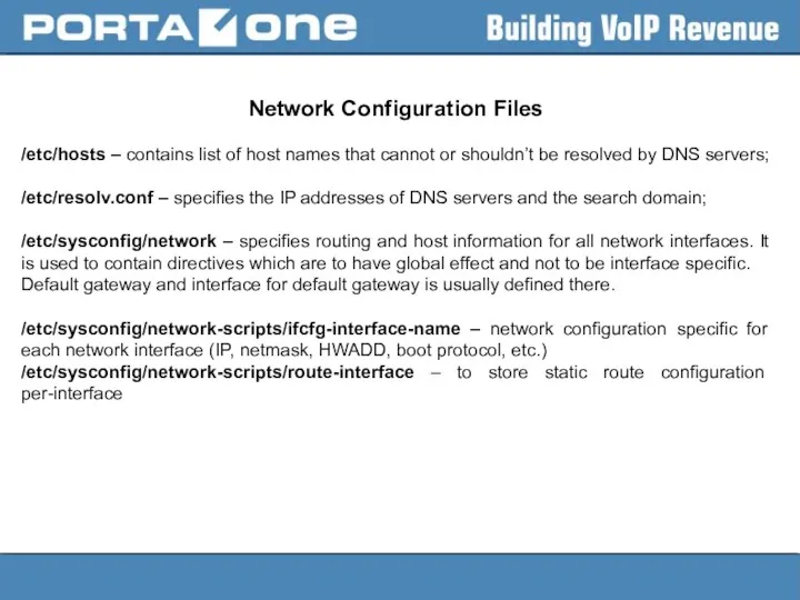
Network Configuration Files
/etc/hosts – contains list of host names that cannot
/etc/hosts – contains list of host names that cannot
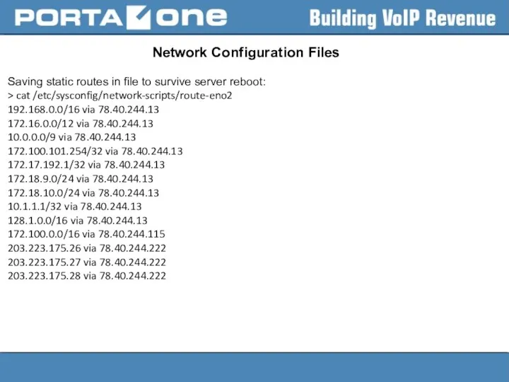
Network Configuration Files
Saving static routes in file to survive server reboot:
>
Network Configuration Files
Saving static routes in file to survive server reboot:
>
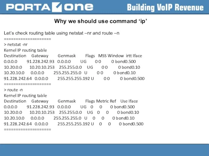
Why we should use command ‘ip’
Let’s check routing table using netstat
Why we should use command ‘ip’
Let’s check routing table using netstat
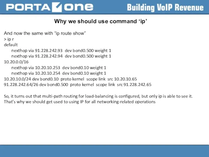
Why we should use command ‘ip’
And now the same with “ip
Why we should use command ‘ip’
And now the same with “ip
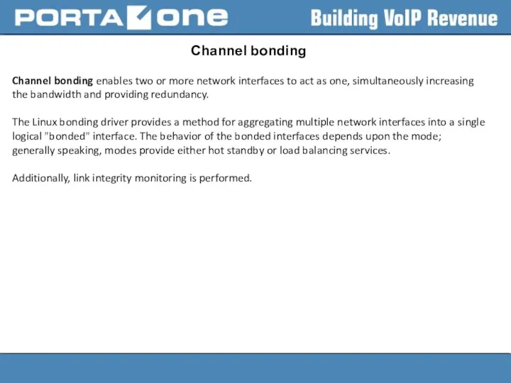
Channel bonding
Channel bonding enables two or more network interfaces to act
Channel bonding
Channel bonding enables two or more network interfaces to act

Bonding mode
mode=
Allows specifies the bonding policy. The can be one
Bonding mode
mode=
Allows specifies the bonding policy. The

Bonding mode
802.3ad or 4 — Sets an IEEE 802.3ad dynamic link
Bonding mode
802.3ad or 4 — Sets an IEEE 802.3ad dynamic link
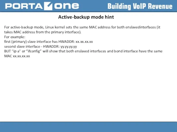
Active-backup mode hint
For active-backup mode, Linux kernel sets the same MAC
Active-backup mode hint
For active-backup mode, Linux kernel sets the same MAC
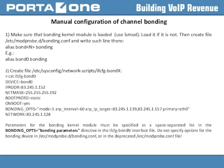
Manual configuration of channel bonding
1) Make sure that bonding kernel module
Manual configuration of channel bonding
1) Make sure that bonding kernel module
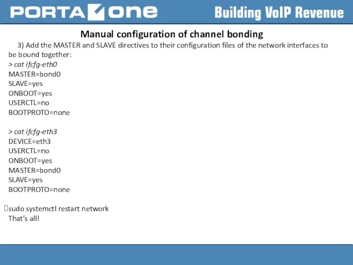
Manual configuration of channel bonding
3) Add the MASTER and SLAVE directives
Manual configuration of channel bonding
3) Add the MASTER and SLAVE directives
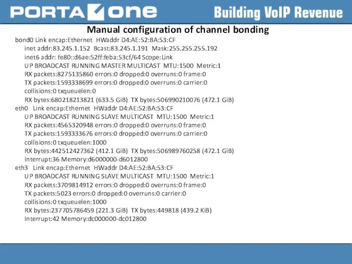
Manual configuration of channel bonding
bond0 Link encap:Ethernet HWaddr D4:AE:52:BA:53:CF
inet addr:83.245.1.152
Manual configuration of channel bonding
bond0 Link encap:Ethernet HWaddr D4:AE:52:BA:53:CF
inet addr:83.245.1.152
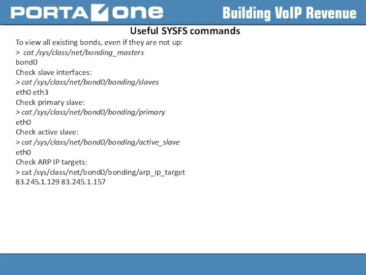
Useful SYSFS commands
To view all existing bonds, even if they are
Useful SYSFS commands
To view all existing bonds, even if they are
Useful SYSFS commands
Bonding statistics:
> cat /proc/net/bonding/bond0
Ethernet Channel Bonding Driver: v3.6.0
Useful SYSFS commands
Bonding statistics:
> cat /proc/net/bonding/bond0
Ethernet Channel Bonding Driver: v3.6.0
Bonding parameters
arp_interval=
Specifies (in milliseconds) how often ARP monitoring occurs.
It is essential
Bonding parameters
arp_interval=
Specifies (in milliseconds) how often ARP monitoring occurs.
It is essential

Bonding parameters
downdelay=
Specifies (in milliseconds) how long to wait after link failure
Bonding parameters
downdelay=
Specifies (in milliseconds) how long to wait after link failure
RHEL 7 peculiarities
According to documentation configuration file for master bonding interface
RHEL 7 peculiarities
According to documentation configuration file for master bonding interface
Network Manager
In Red Hat Enterprise Linux 7, the default networking service
Network Manager
In Red Hat Enterprise Linux 7, the default networking service
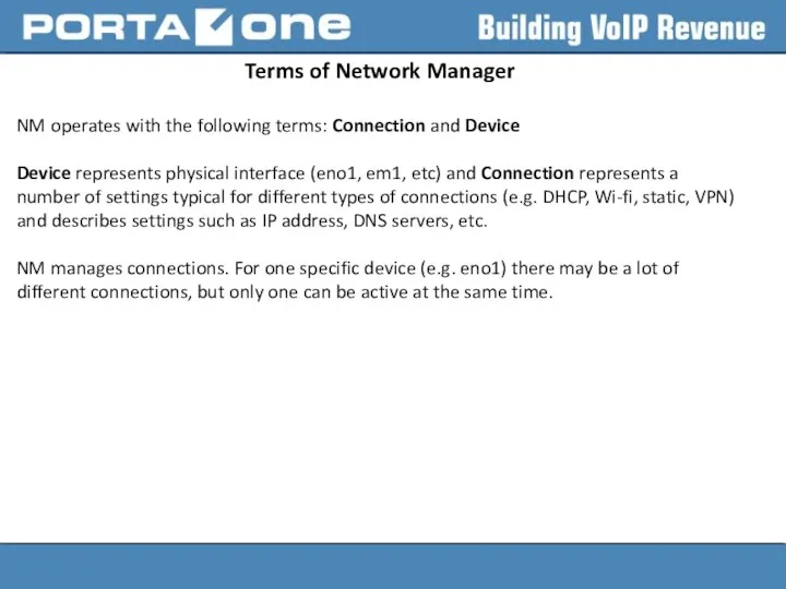
Terms of Network Manager
NM operates with the following terms: Connection and
Terms of Network Manager
NM operates with the following terms: Connection and
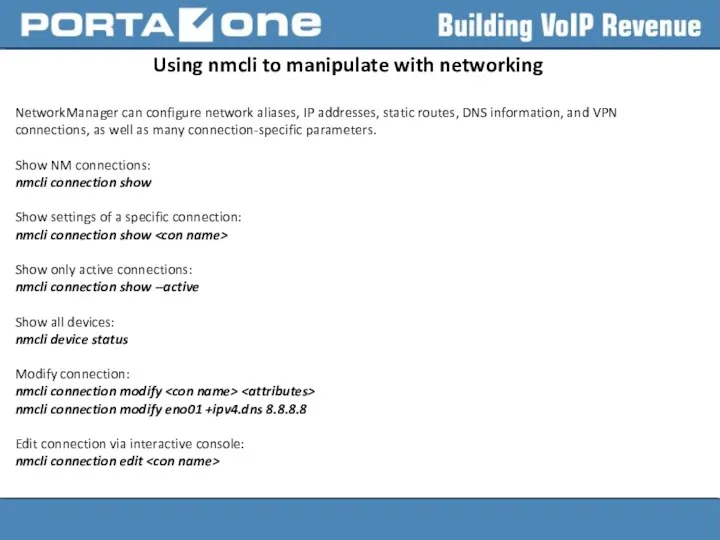
Using nmcli to manipulate with networking
NetworkManager can configure network aliases, IP
Using nmcli to manipulate with networking
NetworkManager can configure network aliases, IP
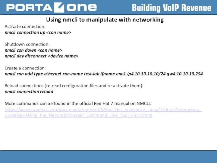
Using nmcli to manipulate with networking
Activate connection:
nmcli connection up
Shutdown
Using nmcli to manipulate with networking
Activate connection:
nmcli connection up
Shutdown
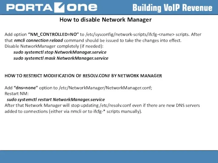
How to disable Network Manager
Add option “NM_CONTROLLED=NO” to /etc/sysconfig/network-scripts/ifcfg- scripts. After
How to disable Network Manager
Add option “NM_CONTROLLED=NO” to /etc/sysconfig/network-scripts/ifcfg-
 Обследование больного с заболеваниями слизистой оболочки полости рта
 Презентация к логопедическому занятию Звук А
 Обогащение полезных ископаемых. Гранулометрический состав руды и продуктов обогащения. (Лекция 3)
 Страны Латинской Америки в середине XIX - начале XX веков. (8 класс)
 Das Deutschland und die Deutsche
 Междуэтажные и чердачные перекрытия по деревянным балкам
 Рекомендации родителям по развитию сюжетно-ролевой игры у детей дошкольного возраста
 Тепловая обработка бетонов
 Синагога и её функции (виртуальная школа АВИВ)
 Вызовы 21-го века. Терроризм
 Презентация к родительскому собранию Профилактика жестокого обращения в семье
 Парогазовые и газотурбинные установки ТЭС
 Лояльность персонала организации
 Интенсивная терапия анафилактического шока
 Правила делового общения, позволяющие создать хорошее впечатление о себе
 День смеха. Первое апреля в разных странах
 Количественные показатели надежности технических систем. (Лекция 2)
 Карта проблемных зон городского округа город Салават Республики Башкортостан на 01.10.2013
 Режимы работы электроэнергетических систем
 Роль бактерий в природе и жизни человека
 Театр Дель Арте
 Цифровая обработка сигналов и изображений
 Механические передачи
 Oiseaux messagers
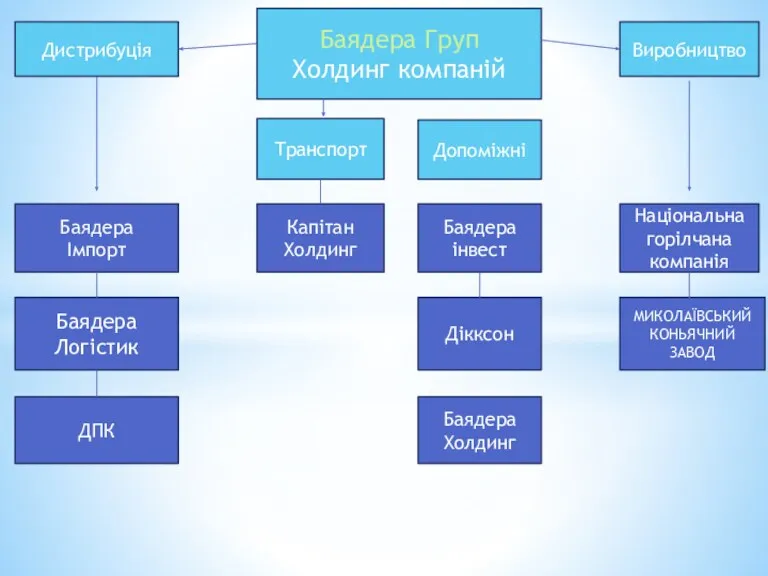 Дистрибуція Баядера Груп Холдинг компаній
 Наладка и кинематика токарно-винторезного станка
 Проект-развития компании ЗЕО
 “Использование УМК в режимных моментах воспитателями ДОУ”.