- Off-Center Fed Dipoles

Содержание
- 2. N1IW Why? Looking for solutions for low band antennas Was abused by a counterpoise as a
- 3. N1IW Off Center Fed Dipole Basics Half wave resonant antenna at lowest frequency of operation Even
- 4. N1IW OCFD Data 80M Used for 10 years 136 feet in length (located at abt 30
- 5. N1IW Why They Work It’s just a dipole! But ½ wave resonant element, then harmonic wire
- 6. N1IW Current Distribution on a Dipole
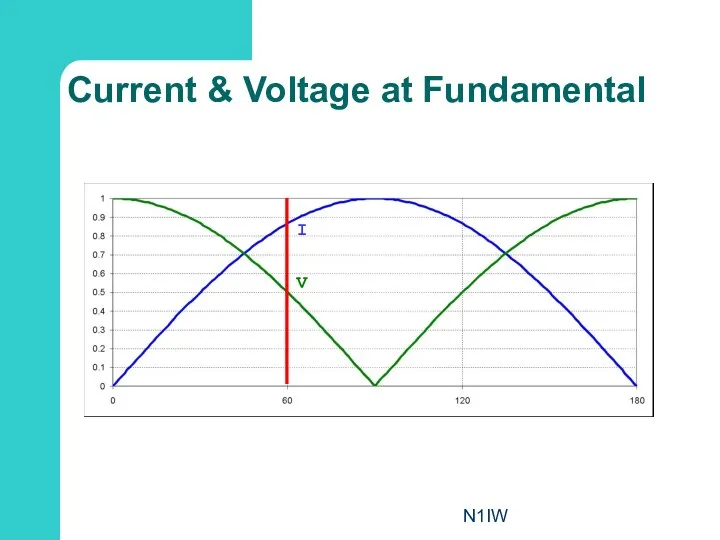
- 7. N1IW Current & Voltage at Fundamental V I
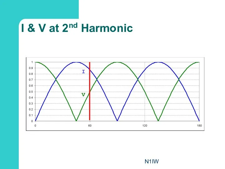
- 8. N1IW I & V at 2nd Harmonic I V
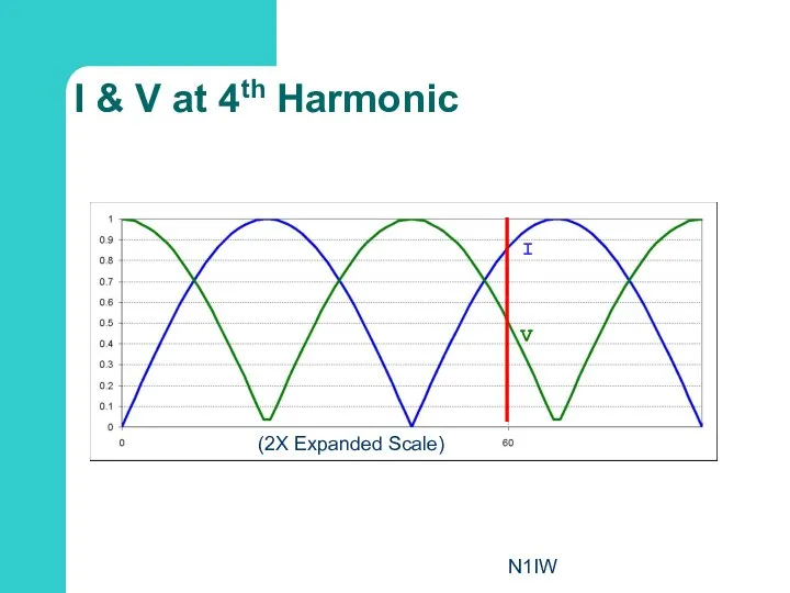
- 9. N1IW I & V at 4th Harmonic I V (2X Expanded Scale)
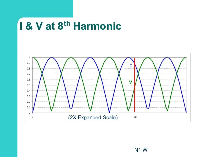
- 10. N1IW I & V at 8th Harmonic I V (2X Expanded Scale)
- 11. N1IW But what about the 6th harmonic? Feed point is at a current minimum Very high
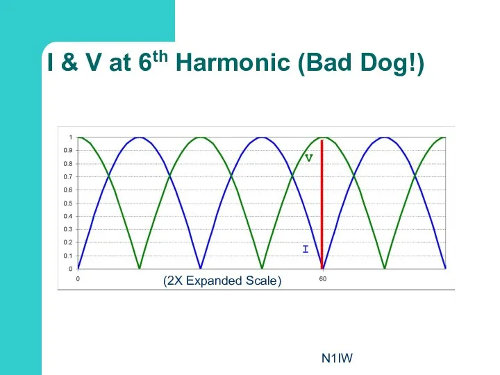
- 12. N1IW I & V at 6th Harmonic (Bad Dog!) I V (2X Expanded Scale)
- 13. N1IW And Odd Harmonics? Same problem: Current minimum
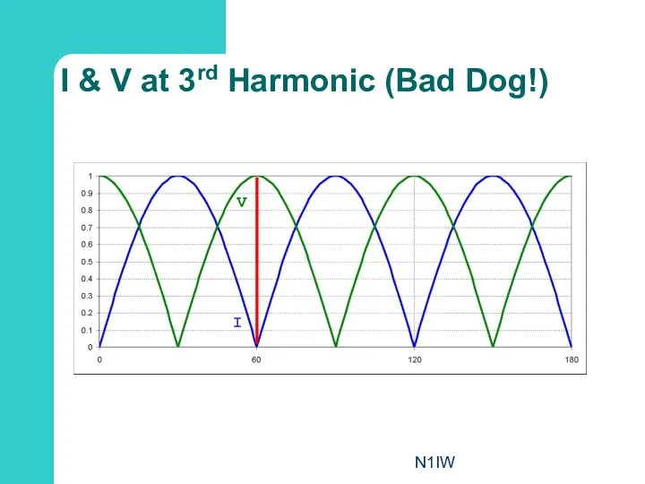
- 14. N1IW I & V at 3rd Harmonic (Bad Dog!) I V
- 15. N1IW Basic Gain Plots
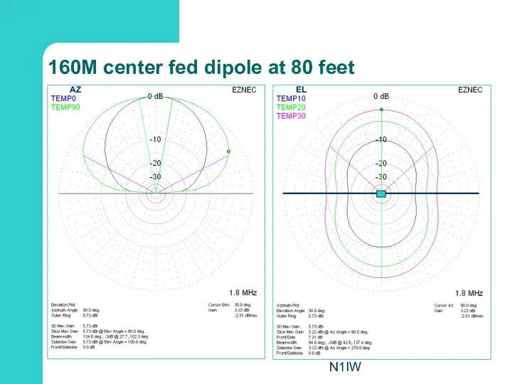
- 16. N1IW 160M center fed dipole at 80 feet EL AZ
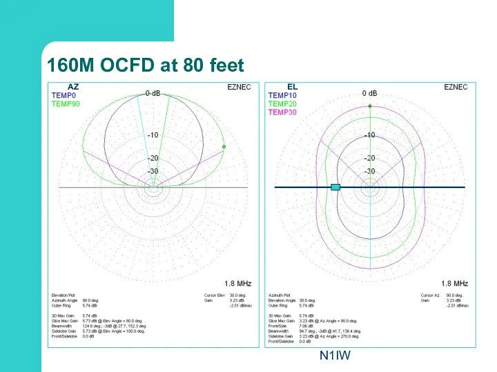
- 17. N1IW 160M OCFD at 80 feet AZ EL
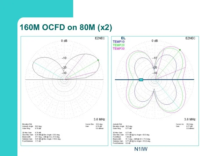
- 18. N1IW 160M OCFD on 80M (x2) EL
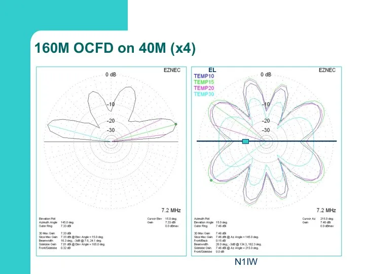
- 19. N1IW 160M OCFD on 40M (x4) EL
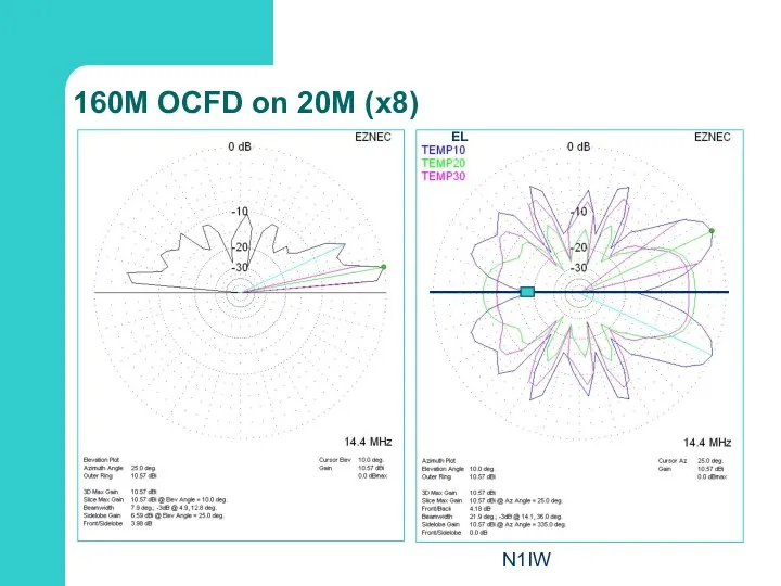
- 20. N1IW 160M OCFD on 20M (x8) EL
- 21. N1IW 160M OCFD on 10M (x16) EL
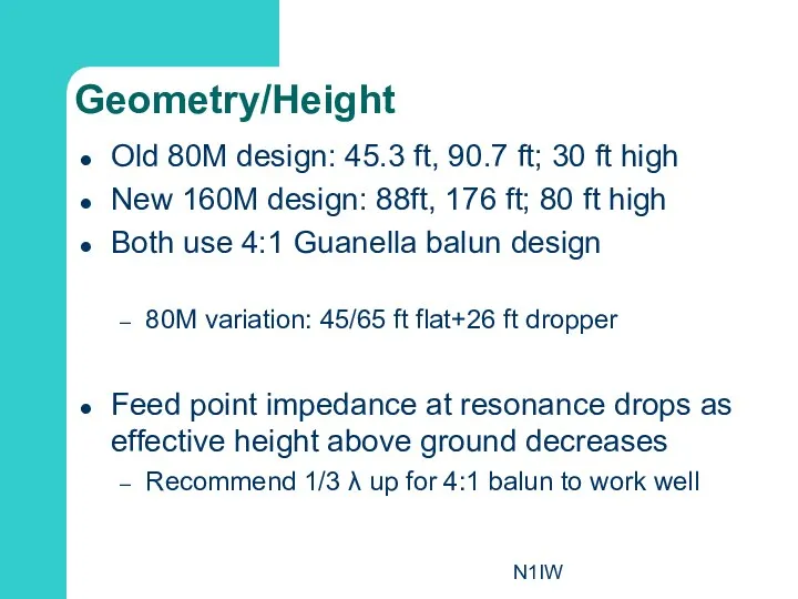
- 22. N1IW Geometry/Height Old 80M design: 45.3 ft, 90.7 ft; 30 ft high New 160M design: 88ft,
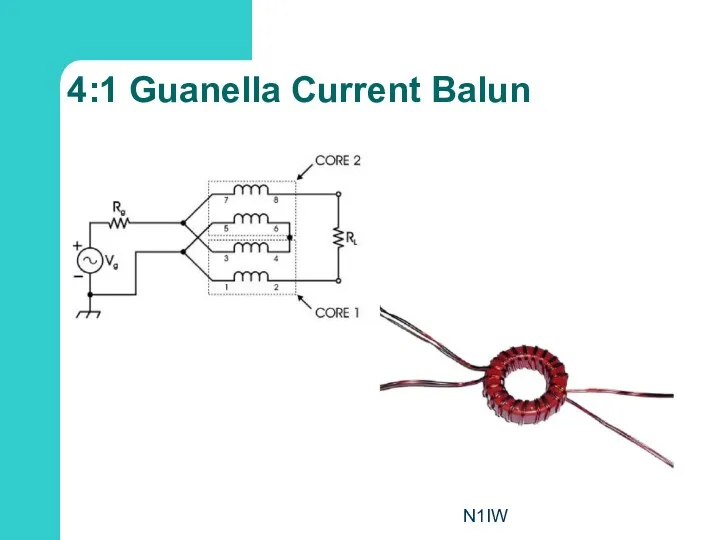
- 23. N1IW 4:1 Guanella Current Balun
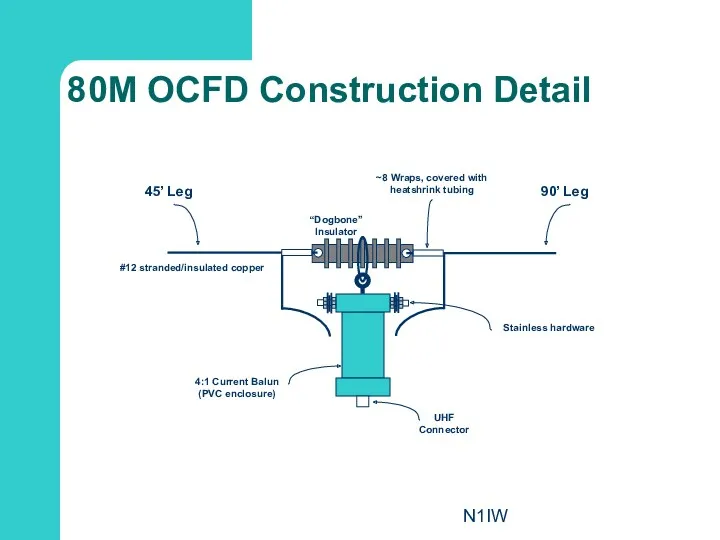
- 24. N1IW 90’ Leg 45’ Leg #12 stranded/insulated copper 4:1 Current Balun (PVC enclosure) ~8 Wraps, covered
- 25. N1IW 176’ Leg 88’ Leg #12 stranded/insulated copper 4:1 Current Balun (PVC enclosure) ~8 Wraps, covered
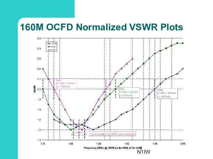
- 26. N1IW 160M OCFD Normalized VSWR Plots
- 27. N1IW OCFD Orientation Issues
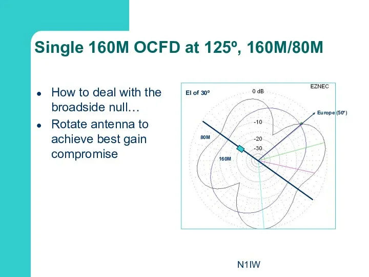
- 28. N1IW Single 160M OCFD at 125º, 160M/80M How to deal with the broadside null… Rotate antenna
- 30. Скачать презентацию
N1IW
Why?
Looking for solutions for low band antennas
Was abused by a counterpoise
N1IW
Why?
Looking for solutions for low band antennas
Was abused by a counterpoise
N1IW
Off Center Fed Dipole Basics
Half wave resonant antenna at lowest frequency
N1IW
Off Center Fed Dipole Basics
Half wave resonant antenna at lowest frequency
N1IW
OCFD Data
80M
Used for 10 years
136 feet in length (located at abt
N1IW
OCFD Data
80M
Used for 10 years
136 feet in length (located at abt
N1IW
Why They Work
It’s just a dipole!
But
½ wave resonant element, then harmonic
N1IW
Why They Work
It’s just a dipole!
But
½ wave resonant element, then harmonic
N1IW
Current Distribution on a Dipole
N1IW
Current Distribution on a Dipole
N1IW
Current & Voltage at Fundamental
V
I
N1IW
Current & Voltage at Fundamental
V
I
N1IW
I & V at 2nd Harmonic
I
V
N1IW
I & V at 2nd Harmonic
I
V
N1IW
I & V at 4th Harmonic
I
V
(2X Expanded Scale)
N1IW
I & V at 4th Harmonic
I
V
(2X Expanded Scale)
N1IW
I & V at 8th Harmonic
I
V
(2X Expanded Scale)
N1IW
I & V at 8th Harmonic
I
V
(2X Expanded Scale)
N1IW
But what about the 6th harmonic?
Feed point is at a current
N1IW
But what about the 6th harmonic?
Feed point is at a current
N1IW
I & V at 6th Harmonic (Bad Dog!)
I
V
(2X Expanded Scale)
N1IW
I & V at 6th Harmonic (Bad Dog!)
I
V
(2X Expanded Scale)
N1IW
And Odd Harmonics?
Same problem: Current minimum
N1IW
And Odd Harmonics?
Same problem: Current minimum
N1IW
I & V at 3rd Harmonic (Bad Dog!)
I
V
N1IW
I & V at 3rd Harmonic (Bad Dog!)
I
V
N1IW
Basic Gain Plots
N1IW
Basic Gain Plots
N1IW
160M center fed dipole at 80 feet
EL
AZ
N1IW
160M center fed dipole at 80 feet
EL
AZ
N1IW
160M OCFD at 80 feet
AZ
EL
N1IW
160M OCFD at 80 feet
AZ
EL
N1IW
160M OCFD on 80M (x2)
EL
N1IW
160M OCFD on 80M (x2)
EL
N1IW
160M OCFD on 40M (x4)
EL
N1IW
160M OCFD on 40M (x4)
EL
N1IW
160M OCFD on 20M (x8)
EL
N1IW
160M OCFD on 20M (x8)
EL

N1IW
160M OCFD on 10M (x16)
EL
N1IW
160M OCFD on 10M (x16)
EL
N1IW
Geometry/Height
Old 80M design: 45.3 ft, 90.7 ft; 30 ft high
New 160M
N1IW
Geometry/Height
Old 80M design: 45.3 ft, 90.7 ft; 30 ft high
New 160M
N1IW
4:1 Guanella Current Balun
N1IW
4:1 Guanella Current Balun
N1IW
90’ Leg
45’ Leg
#12 stranded/insulated copper
4:1 Current Balun
(PVC enclosure)
~8 Wraps, covered with
N1IW
90’ Leg
45’ Leg
#12 stranded/insulated copper
4:1 Current Balun
(PVC enclosure)
~8 Wraps, covered with

N1IW
176’ Leg
88’ Leg
#12 stranded/insulated copper
4:1 Current Balun
(PVC enclosure)
~8 Wraps, covered with
N1IW
176’ Leg
88’ Leg
#12 stranded/insulated copper
4:1 Current Balun
(PVC enclosure)
~8 Wraps, covered with
N1IW
160M OCFD Normalized VSWR Plots
N1IW
160M OCFD Normalized VSWR Plots
N1IW
OCFD Orientation Issues
N1IW
OCFD Orientation Issues
N1IW
Single 160M OCFD at 125º, 160M/80M
How to deal with the broadside
N1IW
Single 160M OCFD at 125º, 160M/80M
How to deal with the broadside
 Что такое компьютерная программа? Урок 1
 Весёлый светофор
 Tale about the analysis of the production
 Лекция 1
 Финансовое мошенничество
 Война 1812 года в творчестве В.В.Верещагина
 презентация проекта По морям, по волнам.
 Соціальні реформи за правління Хрущова
 Конспект НОД по ПДД Приключения Торопыжки
 Интегрированный урок (математика-география) Применение теоремы Пифагора в сельском хозяйстве
 About Bayer
 Географический образ Мексики, часть 2
 Урок географии 10 класс
 Zakon Świętego Benedykta
 Программный комплекс Аккорд ООО НПП АВС-Н
 Нам нужны такие корабли на море
 НеДетское Время. Курс по тайм-менеджменту для школьников
 Движение через железнодорожные пути
 Презентация Разработка школы будущего.
 Фонтанная арматура
 Вегетативная нервная система. Лекция №27
 Наша безопасная дорога
 Инфекционные и неинфекционные заболевания. Профилактика
 TM Devices and gadgets
 Теркон. Контурные тепловые трубы. Разработка и производство пассивных теплопередающих устройств для надежной работы электроники
 Политические режимы
 Headphones mindset
 Математическое моделирование и численные методы в инженерных задачах