- PAP5450DUO service manual

Содержание
- 2. content 1、 Product introduce..………..p3-p4 2、 Disassembly guide ……….p5-p17 3、Structure parts diagram…..p18 4、 Repairing guide …………...p19-p29
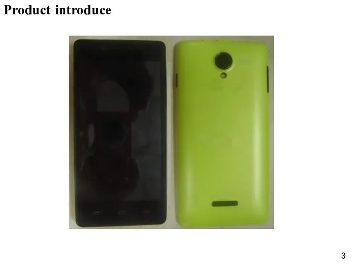
- 3. Product introduce
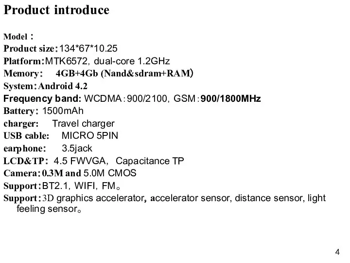
- 4. Product introduce Model : Product size:134*67*10.25 Platform:MTK6572,dual-core 1.2GHz Memory: 4GB+4Gb (Nand&sdram+RAM) System:Android 4.2 Frequency band: WCDMA:900/2100,GSM:900/1800MHz
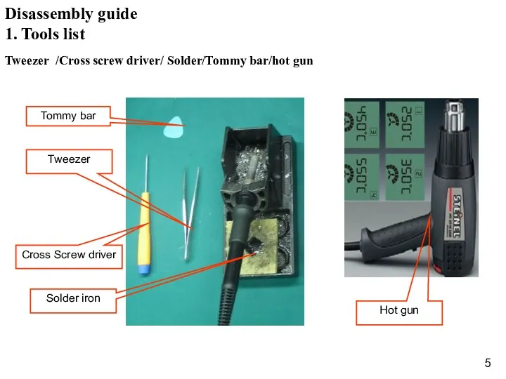
- 5. Hot gun 1. Tools list Tweezer /Cross screw driver/ Solder/Tommy bar/hot gun Disassembly guide
- 6. 2. Battery caver disassembly open the battery cover,as the Fig. 1 Fig. 1 Disassembly guide Battery
- 7. 3. Back caver disassembly 1) Unscrew 12 screws in back cover ,as the Fig.2; Fig. 2
- 8. Fig. 3 2) Disassemble back cover with Tommy bar ,as the Fig.3; Disassembly guide Back cover
- 9. 4.Main board and front cover disassembly 1)The main components of distribution,as the fig.4; Fig.4 Disassembly guide
- 10. 2)remove two screws and open the LCD con.& TP con. ,and remove the volume key FPC
- 11. 3)open the main board and remove the RF cable con. And main FPC con..as the FIG.6
- 12. remove the light sensor and camera,as the fig.7; 5. Front and Back camera & light sensor
- 13. Fig.9 remove the Speaker camera and receiver,as the FIG.9; 7. Speaker & receiver disassembly Disassembly guide
- 14. Fig.10 8. RF cable and Main FPC disassembly Remove the RF cable and Main FPC ,as
- 15. Fig.11 9. Sub PCBA disassembly remove the sub PCBA from the ,as the fig.11; Disassembly guide
- 16. Fig.12 10.MIC disassembly Remove the MIC,as the fig.12; Disassembly guide MIC con.
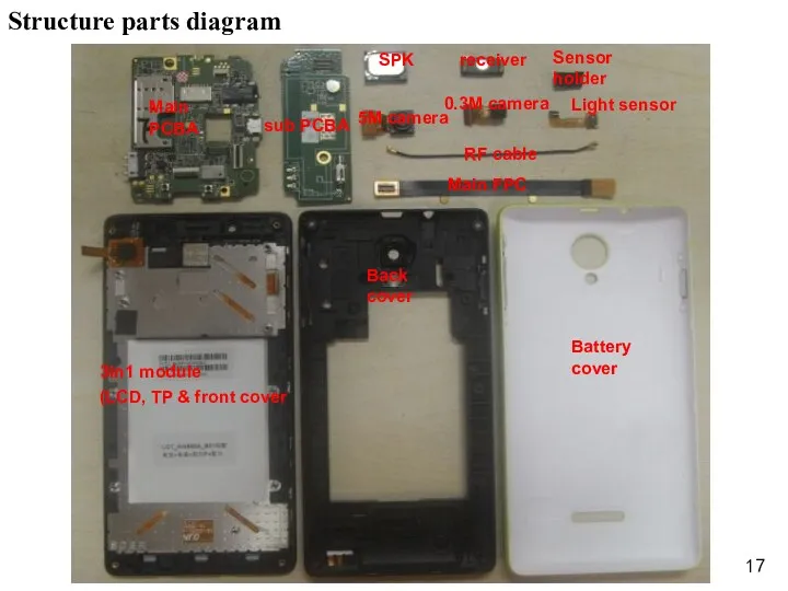
- 17. Structure parts diagram 3in1 module (LCD, TP & front cover Back cover Battery cover Main PCBA
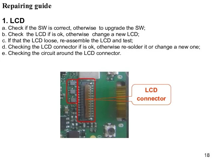
- 18. Repairing guide 1. LCD a. Check if the SW is correct, otherwise to upgrade the SW;
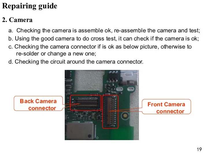
- 19. 2. Camera a. Checking the camera is assemble ok, re-assemble the camera and test; b. Using
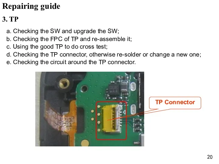
- 20. 3. TP a. Checking the SW and upgrade the SW; b. Checking the FPC of TP
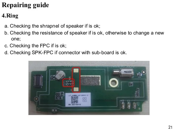
- 21. 4.Ring a. Checking the shrapnel of speaker if is ok; b. Checking the resistance of speaker
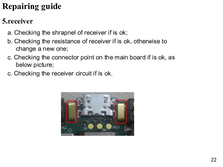
- 22. 5.receiver a. Checking the shrapnel of receiver if is ok; b. Checking the resistance of receiver
- 23. a. Checking the MIC and Vibrator is cold soldering, re-solder it; b. Change the MIC and
- 24. a. Checking the shrapnel of earphone if is ok; b. Checking the connector point on the
- 25. a. Checking the voltage of battery if is 3.8-4.2V and connect ok; b. Upgrade the SW;
- 26. a. Checking the voltage of battery if is over 3.4V; b. Checking the charger and USB
- 27. Checking the connector of T –card and SIM card; Change the connector of T –card and
- 28. a. Checking RF line if that is broken; b. Checking RF line assemble if is ok;
- 30. Скачать презентацию
content
1、 Product introduce..………..p3-p4
2、 Disassembly guide ……….p5-p17
3、Structure parts diagram…..p18
content
1、 Product introduce..………..p3-p4
2、 Disassembly guide ……….p5-p17
3、Structure parts diagram…..p18
Product introduce
Product introduce
Product introduce
Model :
Product size:134*67*10.25
Platform:MTK6572,dual-core 1.2GHz
Memory: 4GB+4Gb (Nand&sdram+RAM)
System:Android 4.2
Frequency band: WCDMA:900/2100,GSM:900/1800MHz
Battery:
Product introduce
Model :
Product size:134*67*10.25
Platform:MTK6572,dual-core 1.2GHz
Memory: 4GB+4Gb (Nand&sdram+RAM)
System:Android 4.2
Frequency band: WCDMA:900/2100,GSM:900/1800MHz
Battery:
Hot gun
1. Tools list
Tweezer /Cross screw driver/ Solder/Tommy bar/hot gun
Disassembly
Hot gun
1. Tools list
Tweezer /Cross screw driver/ Solder/Tommy bar/hot gun
Disassembly
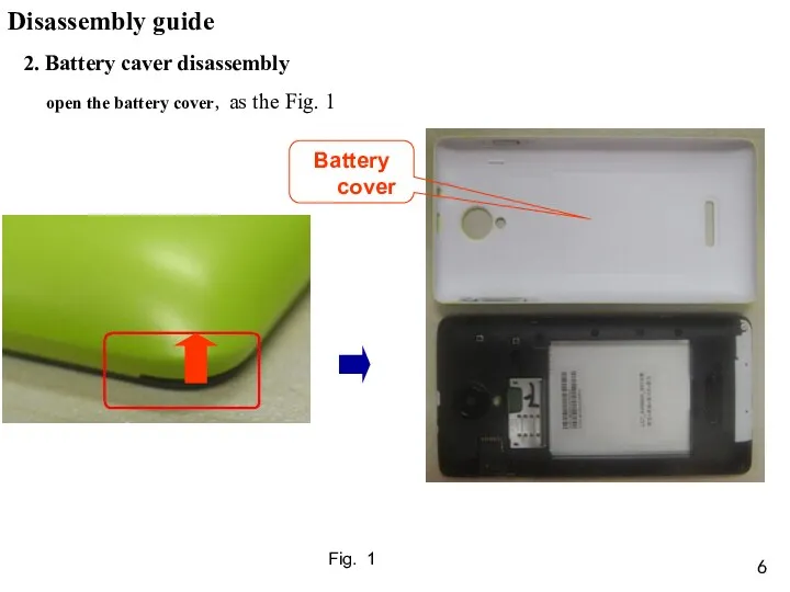
2. Battery caver disassembly
open the battery cover,as the Fig. 1
Fig. 1
Disassembly
2. Battery caver disassembly
open the battery cover,as the Fig. 1
Fig. 1
Disassembly
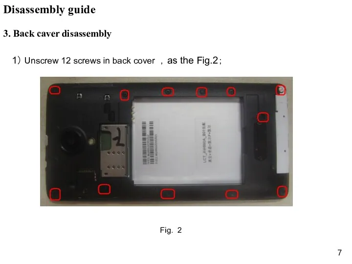
3. Back caver disassembly
1) Unscrew 12 screws in back cover ,as
3. Back caver disassembly
1) Unscrew 12 screws in back cover ,as
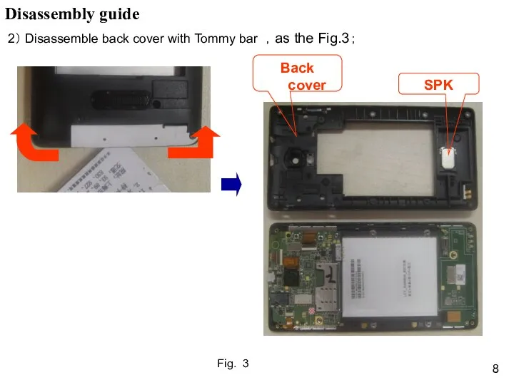
Fig. 3
2) Disassemble back cover with Tommy bar ,as the Fig.3;
Disassembly
Fig. 3
2) Disassemble back cover with Tommy bar ,as the Fig.3;
Disassembly
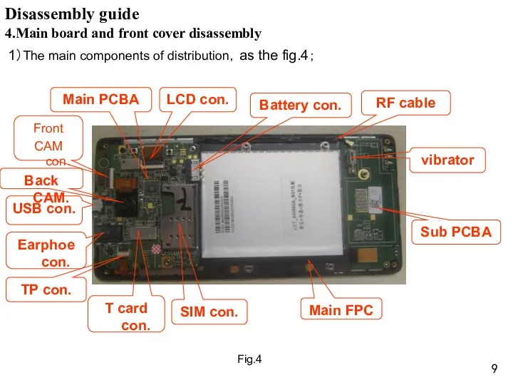
4.Main board and front cover disassembly
1)The main components of distribution,as
4.Main board and front cover disassembly
1)The main components of distribution,as
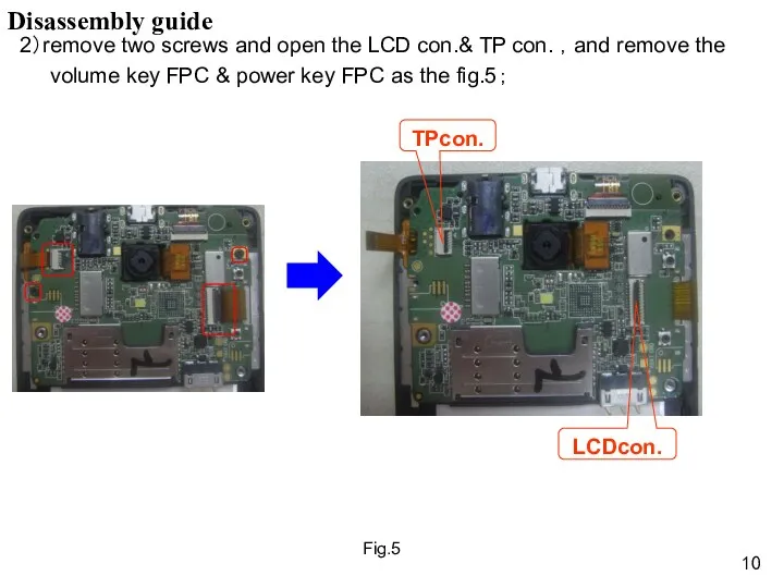
2)remove two screws and open the LCD con.& TP con.
2)remove two screws and open the LCD con.& TP con.
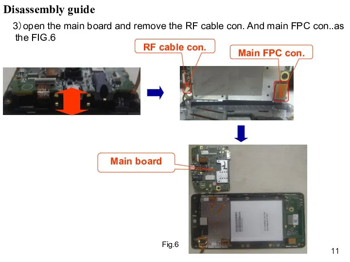
3)open the main board and remove the RF cable con.
3)open the main board and remove the RF cable con.
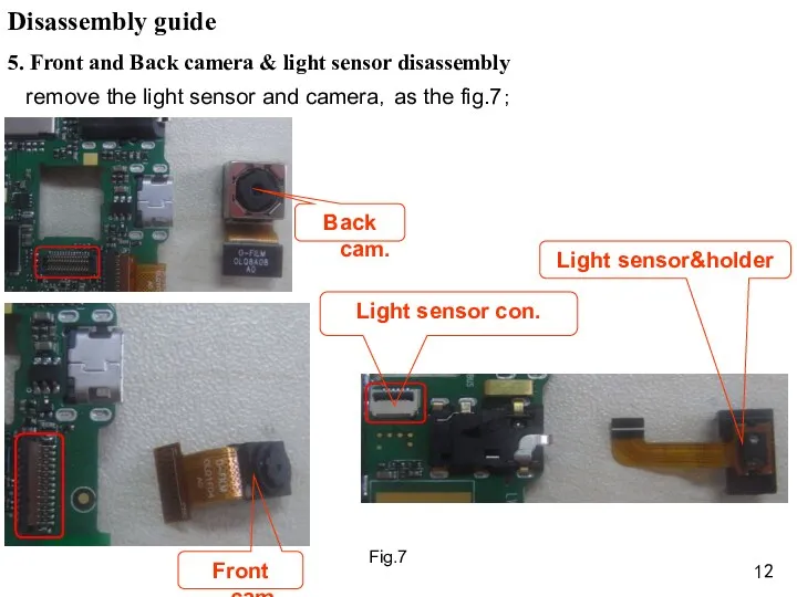
remove the light sensor and camera,as the fig.7;
5. Front and
remove the light sensor and camera,as the fig.7;
5. Front and
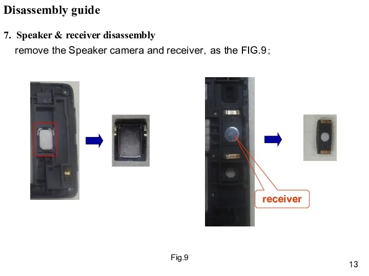
Fig.9
remove the Speaker camera and receiver,as the FIG.9;
7. Speaker &
Fig.9
remove the Speaker camera and receiver,as the FIG.9;
7. Speaker &
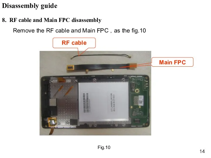
Fig.10
8. RF cable and Main FPC disassembly
Remove the RF cable and
Fig.10
8. RF cable and Main FPC disassembly
Remove the RF cable and
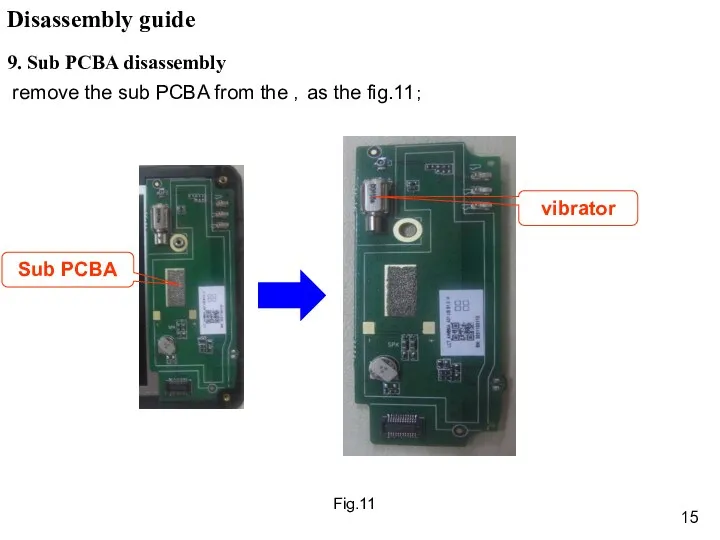
Fig.11
9. Sub PCBA disassembly
remove the sub PCBA from the ,as
Fig.11
9. Sub PCBA disassembly
remove the sub PCBA from the ,as
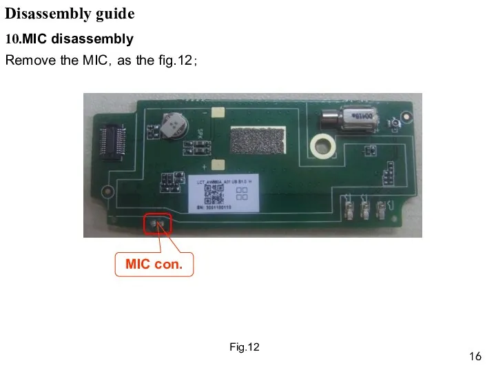
Fig.12
10.MIC disassembly
Remove the MIC,as the fig.12;
Disassembly guide
MIC con.
Fig.12
10.MIC disassembly
Remove the MIC,as the fig.12;
Disassembly guide
MIC con.
Structure parts diagram
3in1 module
(LCD, TP & front cover
Back cover
Battery cover
Main PCBA
sub
Structure parts diagram
3in1 module
(LCD, TP & front cover
Back cover
Battery cover
Main PCBA
sub
Repairing guide
1. LCD
a. Check if the SW is correct, otherwise to
Repairing guide
1. LCD
a. Check if the SW is correct, otherwise to
2. Camera
a. Checking the camera is assemble ok, re-assemble the camera
2. Camera
a. Checking the camera is assemble ok, re-assemble the camera
3. TP
a. Checking the SW and upgrade the SW;
b. Checking the
3. TP
a. Checking the SW and upgrade the SW;
b. Checking the
4.Ring
a. Checking the shrapnel of speaker if is ok;
b. Checking the
4.Ring
a. Checking the shrapnel of speaker if is ok;
b. Checking the
5.receiver
a. Checking the shrapnel of receiver if is ok;
b. Checking
5.receiver
a. Checking the shrapnel of receiver if is ok;
b. Checking
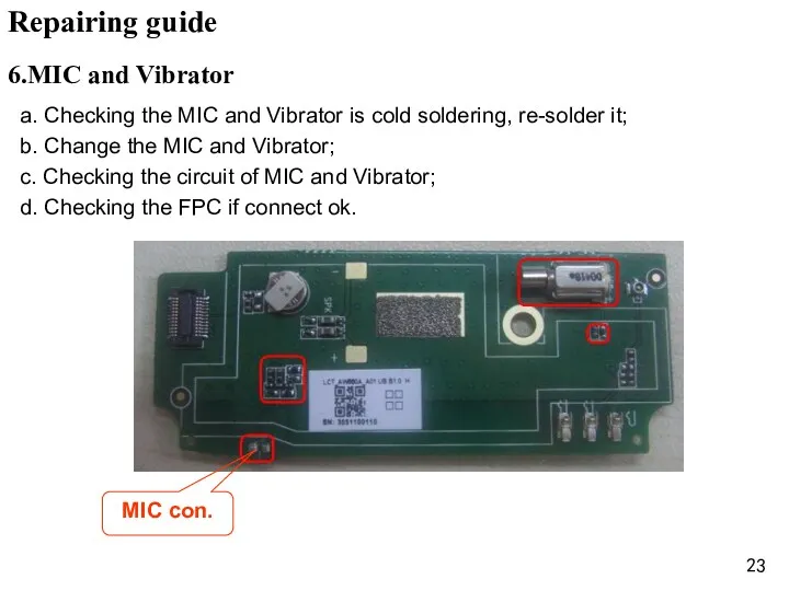
a. Checking the MIC and Vibrator is cold soldering, re-solder it;
b.
a. Checking the MIC and Vibrator is cold soldering, re-solder it;
b.
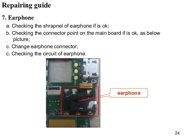
a. Checking the shrapnel of earphone if is ok;
b. Checking the
a. Checking the shrapnel of earphone if is ok;
b. Checking the
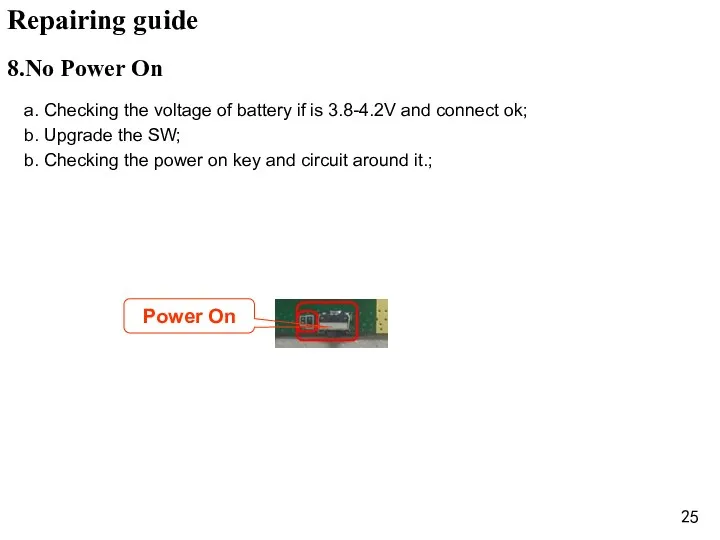
a. Checking the voltage of battery if is 3.8-4.2V and connect
a. Checking the voltage of battery if is 3.8-4.2V and connect
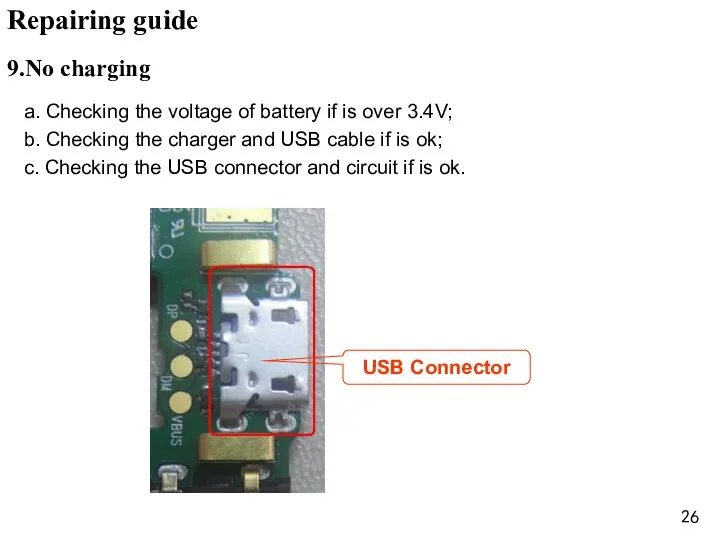
a. Checking the voltage of battery if is over 3.4V;
b. Checking
a. Checking the voltage of battery if is over 3.4V;
b. Checking
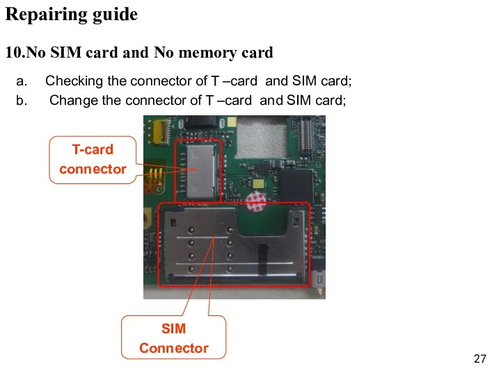
Checking the connector of T –card and SIM card;
Change the
Checking the connector of T –card and SIM card;
Change the
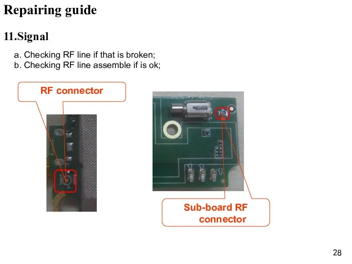
a. Checking RF line if that is broken;
b. Checking RF
a. Checking RF line if that is broken;
b. Checking RF
 Физиологические механизмы регуляции веса тела
 Озеро Байкал
 Производственная практика на АО Алмазы Анабара. Промывка геологических проб
 Услуга Мобильный VPN
 : Домашние животные
 Материалы по теме месяца
 Британский институт стандартов. Опыт нормирования в области информационного моделирования
 Классный час Огонь - друг и враг человека
 Выполнение работ по одной или нескольким профессиям рабочих, должностям служащих
 Презентация проекта Мое имя
 Наш лучший друг - Агния Барто
 Группа Крайбург и продукты
 Оксиды
 Торговая Стратегия “ Прикрытый Интрадей”
 Строительство школ и детсадов в Пермском крае
 Разработка технологического процесса изготовления корпуса
 Игротерапия
 Создание мультимедийной презентации. Практическая работа
 Валентин Александрович Серов
 Мое любимое место в Ижевске детская библиотека им. Максима Горького
 Презентация Семь чудес Малорхангельска
 Futur simple. Французский язык
 People. 7 класс
 Человек познает мир
 Проект Для любимой мамочки!
 Презентация проекта Создание книги Краткой энциклопедии правил поведения на улице для детей и взрослых
 кроссворд для речевого развлечения
 Интегральная фотонная компонентная база для высокоскоростных систем телекоммуникаций