- Profile leveling

Содержание
- 2. Profile Leveling To collect data about topography along a reference line. Mainly to compute volumes of
- 3. Staking and Stationing the Reference Line First, topography is studied, a center line is chosen. Second,
- 4. For example station K is (10+24.5) = 1024.5ft from a certain zero, may not exist. First
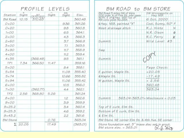
- 5. First a backsight at a BM is observed. Then, a number of intermediate foresights are observed
- 6. Figure 5.11 Profile leveling. Figure 5-11 Profile Leveling
- 7. Elevation computation: Elevation of line of sight (LS) = EBM + BSBM. Elevation of any intermediate
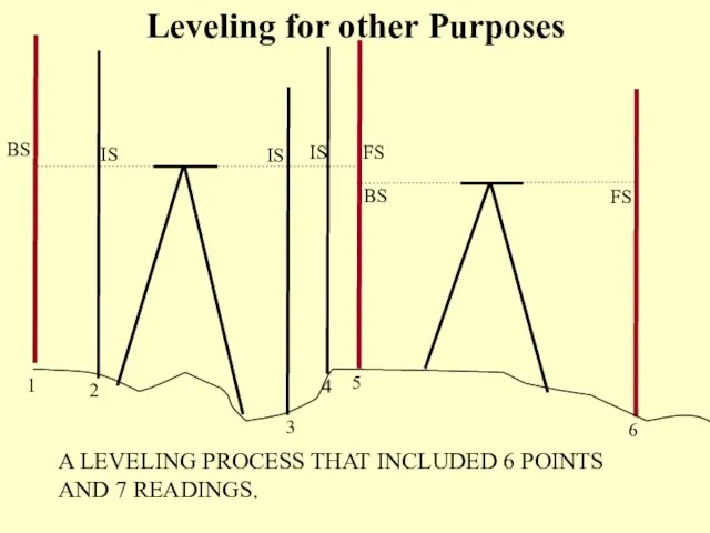
- 8. BS IS IS IS FS BS FS 1 2 3 4 5 6 A LEVELING PROCESS
- 9. Example: Compute the elevations of points 1 through 5 if the elevation of the BM is
- 10. Answer = 2.11 + 22.13 24.24 = 24.24 – 1.14 23.40 = 24.24 – 0.95 23.10
- 12. Drawing and Using Profiles Drawn using a software now.The following is for reference only, will not
- 14. Скачать презентацию

Profile Leveling
To collect data about topography along a reference line.
Mainly to
Profile Leveling
To collect data about topography along a reference line.
Mainly to
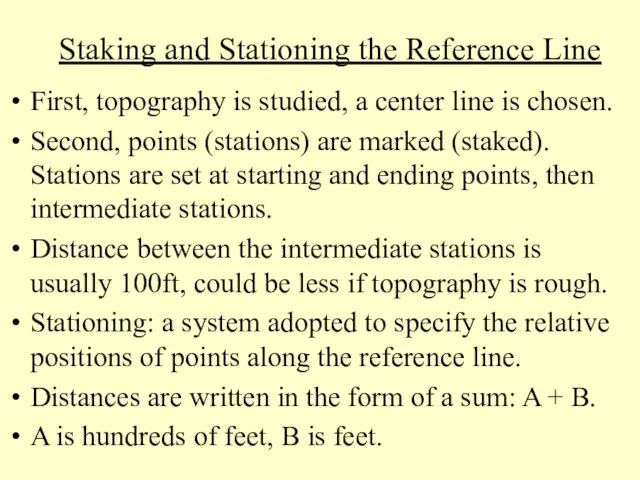
Staking and Stationing the Reference Line
First, topography is studied, a
Staking and Stationing the Reference Line
First, topography is studied, a
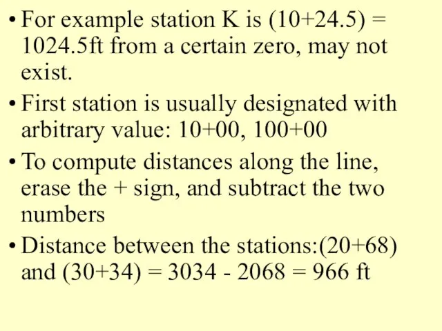
For example station K is (10+24.5) = 1024.5ft from a certain
For example station K is (10+24.5) = 1024.5ft from a certain
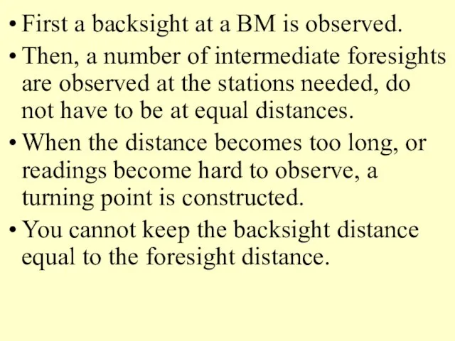
First a backsight at a BM is observed.
Then, a number of
First a backsight at a BM is observed.
Then, a number of
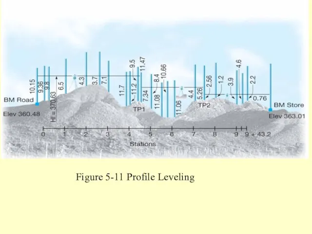
Figure 5.11 Profile leveling.
Figure 5-11 Profile Leveling
Figure 5.11 Profile leveling.
Figure 5-11 Profile Leveling
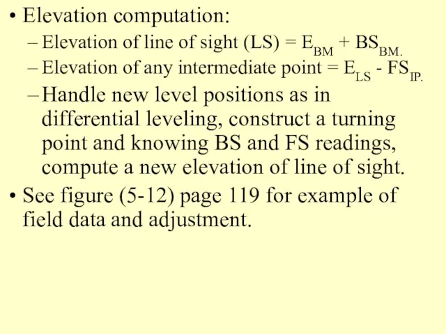
Elevation computation:
Elevation of line of sight (LS) = EBM + BSBM.
Elevation
Elevation computation:
Elevation of line of sight (LS) = EBM + BSBM.
Elevation
BS
IS
IS
IS
FS
BS
FS
1
2
3
4
5
6
A LEVELING PROCESS THAT INCLUDED 6 POINTS AND 7 READINGS.
Leveling for
BS
IS
IS
IS
FS
BS
FS
1
2
3
4
5
6
A LEVELING PROCESS THAT INCLUDED 6 POINTS AND 7 READINGS.
Leveling for
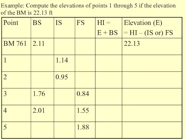
Example: Compute the elevations of points 1 through 5 if the
Example: Compute the elevations of points 1 through 5 if the
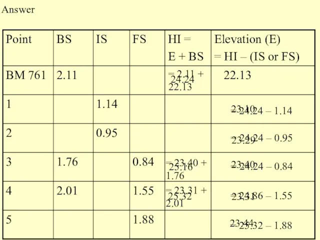
Answer
= 2.11 + 22.13
24.24
= 24.24 – 1.14
23.40
= 24.24 – 0.95
23.10
= 24.24
Answer
= 2.11 + 22.13
24.24
= 24.24 – 1.14
23.40
= 24.24 – 0.95
23.10
= 24.24
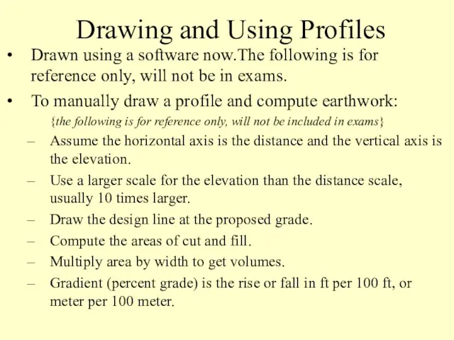
Drawing and Using Profiles
Drawn using a software now.The following is for
Drawing and Using Profiles
Drawn using a software now.The following is for
 Технология работы по организации хранения личных вещей клиентов в гостинице
 Диагностические методики для оценки развития познавательного интереса дошкольников.
 Методы исследования процессов переработки полимеров
 Внеурочная работа по предметам естественно-математического цикла
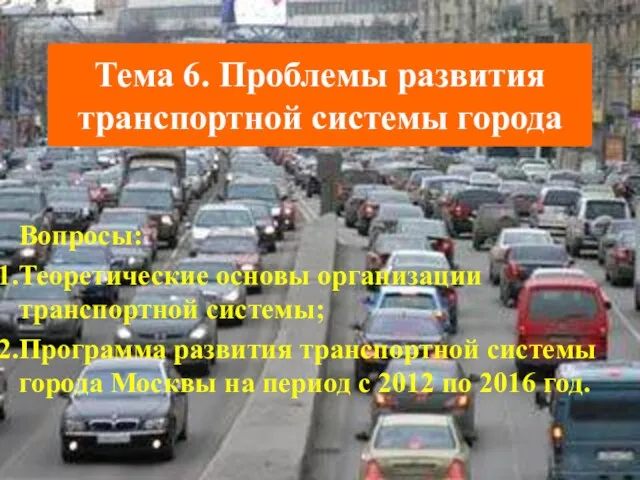 Проблемы развития транспортной системы города
 Методы измерения температуры при испытаниях
 Методика обследования органов дыхания: расспрос, осмотр
 Мелиорация сельскохозяйственных земель
 Презентация к уроку Типы химической связи
 Формирование морально-волевых качеств при занятиях физической культурой и спортом детей подросткового возраста
 Параметрический анализ. Параметрические модели функционирования типовых радиоустройств. (Лекция 2)
 Презентация Пейзажи России
 Логопедическое обследование дошкольников на основе лингвистического материала, содержащего звуки Х и Х’
 Запрос котировок в электронной форме
 Свариваемость углеродистых сталей
 И для меня бы не было России без маленькой Самойловки моей
 Предварительное техническое предложение на поставку беспилотного вертолетного комплекса “INDELA”
 Ко Дню Матери
 Классный час Поселку Мостовскому 120 лет: помним,гордимся, наследуем
 Урок по физике -химии для 5 класса Строение вещества. Химические элементы
 Технические средства реализации информационных процессов
 Презентация Мои фото
 Алкадиены. 10 класс
 Завершающий этап гражданских войн. Рим в 78-31 гг. до н. э.: от республики - к военной монархии. Часть I
 Активизация интереса к изучению коми языка посредством игры
 Характеристики излучения звезд. 10-11 класс
 Предоставление государственной услуги по лицензированию подземных вод
 Лекция №11 для подготовки к ЕГЭ для 11(профильного) класса по теме Основания. Щёлочи. Амфотерные гидроксиды