- Repair Manual. Citaq Android POS

Содержание
- 2. CITAQ V8 Parameter
- 3. CITAQ V8 Parameter
- 4. 1.CITAQ V8 Disassembly
- 5. 1.1 Appearance---Front 3 1:8’’ touch screen(Capacity) 2:Indicator 3: V8 cover 4:Side USB port 4 Press the
- 6. 1.1Appearance---Back 1:Power Switch 2:Lan Port 3:Rear USBX2, RS232 x 1 4:Adaptor port 5:Cash drawer port 1
- 7. 1.1 Internal view 1:Printer mechanism 2:Mechanism 3、4:Paper feeder rolls X4 5:SIM、TF card slot 1 2 3
- 8. 1.2 Host unit disassembly 1.2.1 Disassembly of Plastic Base 1、Take out screws marked 2、Turn the switch
- 9. 1.2 Host unit disassembly 1.2.2 Disassemble the screen 1、Unscrew all screws marked in pic 2、Lift the
- 10. 1.2 Host Unit Disassembly 1.2.3 Disassemble the Screen cables 1、Pry the breaches pic showed by a
- 11. 1.2 Host Unit Disassembly 1.2.4 Disassemble the base metal cover 1、Unscrew the marked screws and push
- 12. 1.2 Host Unit Disassembly 1.2.5 Disassemble the printer board Switch Cable Sensor Printer Head USB Connect
- 13. 1.2 Host Unit Disassembly 1.2.6 Disassemble the plastic frame 1、Unscrew the marked screws and open the
- 14. 1.2 Host Unit Disassembly 1.2.2 Disassemble the sensor 1、Unscrew the marked screws to take sensor apart.
- 15. 1.2 Host Unit Disassembly 1.2.6 Disassemble the printer mechanism 1、Cut the marked plastic wire 2、Unscrew the
- 16. 1.2 Host Unit Disassembly 1.2.7 Disassemble the printer mechanism 1、Take out the connector from cable slot,
- 17. 1.3 Host Unit Disassembly 1.3.1 Disassemble screen back 1、Unscrew the marked screws to take out this
- 18. 1.3 Host Unit Disassembly 1.3.2 Disassemble Main board 1、Pull out WIFI cable 2、Push out the marked
- 19. 1.3 Disassembly of Screen 1.3.3 Disassemble speaker, battery, indicator, Wifi antenna and 3G antenna 1、Tear the
- 20. 1.3 Disassembly of Screen 1.3.4 Disassemble metal fixture of screen 1、Remove marked screws to disassemble the
- 21. 1.3 Disassembly of Screen 1.3.5 Disassemble LCD Panel 1、First to pull up the edge of LCD
- 22. 1.3 Disassembly of Screen 1.3.6 Disassemble touch screen 1、Firstly heat up the edges which marked in
- 23. 2.CITAQ V8 FAQ
- 24. V8 FAQ and solution 1、Eliminate the black screen when turning on Try to replace LCD panel
- 26. Скачать презентацию
 Разъяснения по заполнению справок о доходах формы 2-НДФЛ нового образца
 Эволюция вселенной
 Духовно-нравственное развитие и воспитание младшего школьника через приобщение его к отечественной религиозно-культурной традиции
 Производство серной кислоты H2SO4
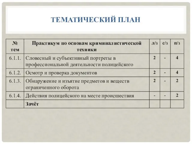 Словесный и субъективный портреты в профессиональной деятельности полицейского
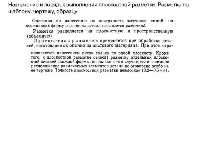 Назначение и порядок выполнения плоскостной разметки. Разметка по шаблону, чертежу, образцу
 Prezentatsia
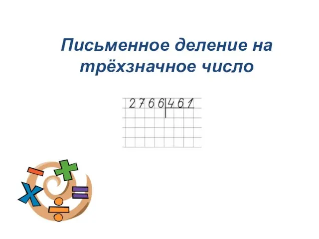 Письменное деление на трёхзначное число
 АСПЕКТЫ КОРРЕКЦИОННОЙ РАБОТЫ ВОСПИТАТЕЛЯ ЛОГОПЕДИЧЕСКОЙ ГРУППЫ.
 Деловое общение
 English in Use
 Презентация Фольклорные праздники как средство нравственного воспитания детей дошкольного возраста
 Пути введения лекарственных средств. Фармакокинетика
 Программируемые логические структуры
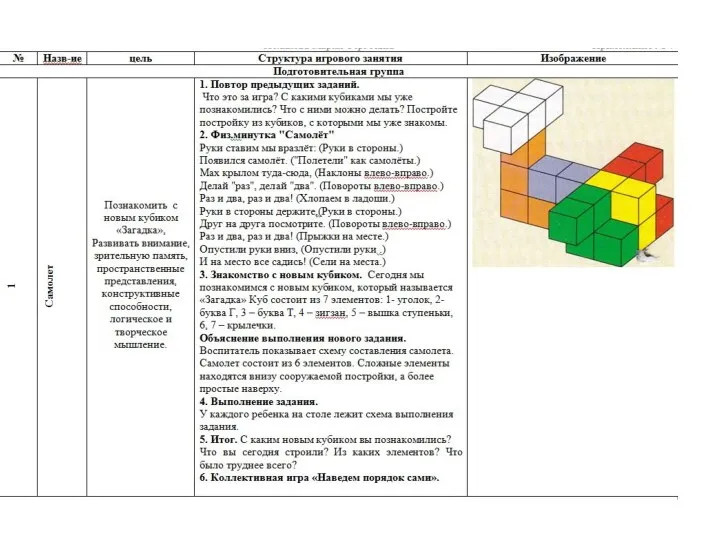 Перспективное планирование работы с Логическими кубиками для всех Б.П.Никтина подготовительная группа
 Порушення фонематичного слуху як основа сенсорної афазії. Акустико-семантичні порушення
 Исследование эффективности маркетинговых коммуникаций
 Реформы и революции
 Балалық шақтағы қан жасау органдарының анатомофизиологиялық ерекшелігі визуальды диагностикасы
 Звёзды. Рождение и смерть звёзд
 к конкурсу ПРЕДАНЬЕ СТАРИНЫ ГЛУБОКОЙ номинация Святки
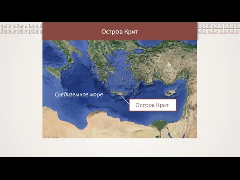 Остров Крит
 Организация и выполнение сборки и монтажа часов с термометром и таймером в соответствии с технической документацией
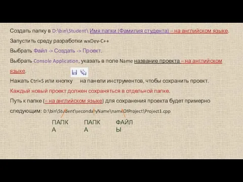 Создание программы
 Праздник первых каникул
 Антигистаминные средства
 Фотографии к викторине о животных
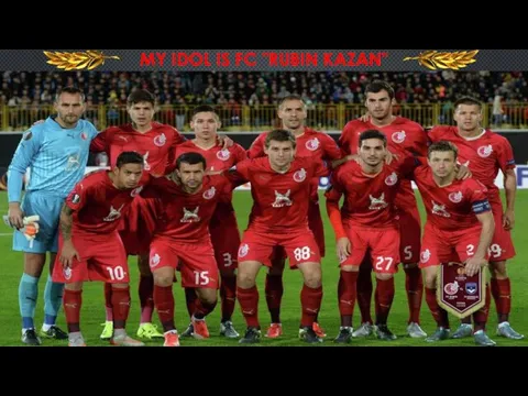 My idol is FC Rubin Kazan