- Simple Digital and Analog Inputs

Содержание
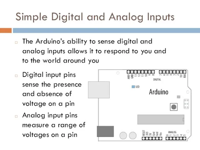
- 2. Simple Digital and Analog Inputs The Arduino’s ability to sense digital and analog inputs allows it
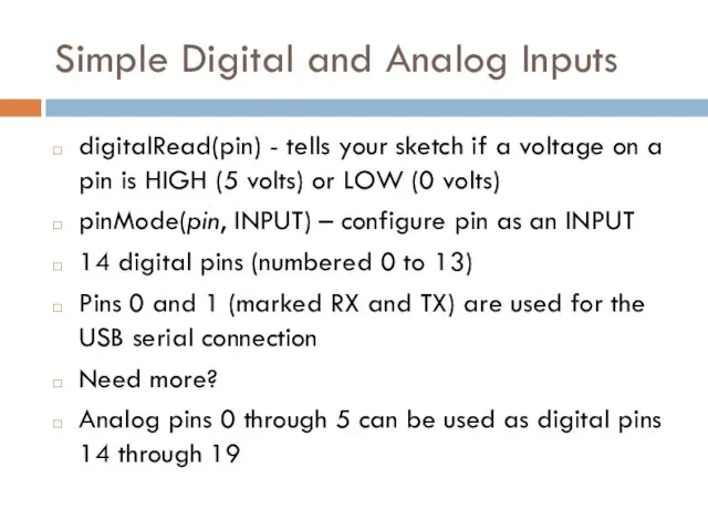
- 3. Simple Digital and Analog Inputs digitalRead(pin) - tells your sketch if a voltage on a pin
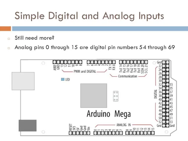
- 4. Simple Digital and Analog Inputs Still need more? Analog pins 0 through 15 are digital pin
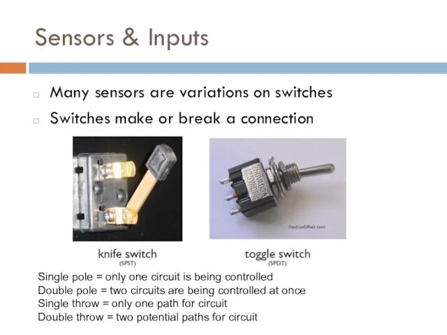
- 5. Sensors & Inputs Many sensors are variations on switches Switches make or break a connection Single
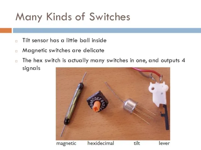
- 6. Many Kinds of Switches Tilt sensor has a little ball inside Magnetic switches are delicate The
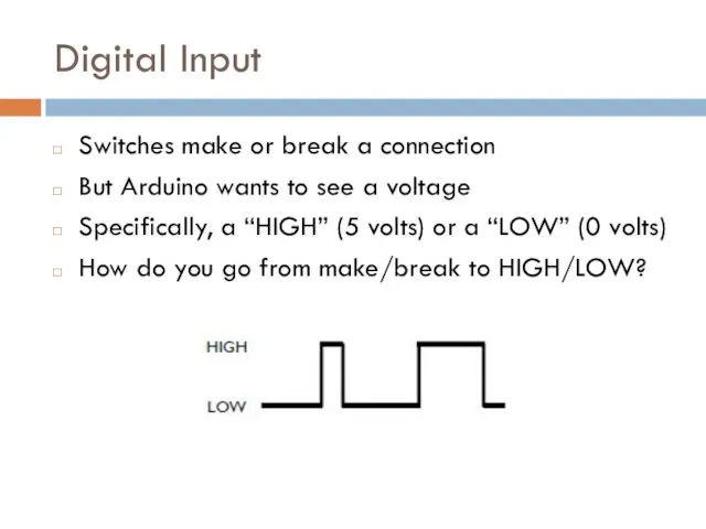
- 7. Digital Input Switches make or break a connection But Arduino wants to see a voltage Specifically,
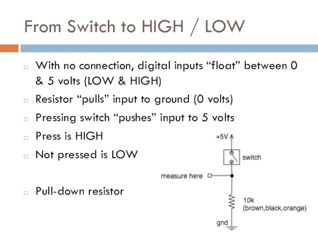
- 8. From Switch to HIGH / LOW With no connection, digital inputs “float” between 0 & 5
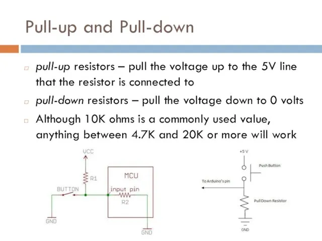
- 9. Pull-up and Pull-down pull-up resistors – pull the voltage up to the 5V line that the
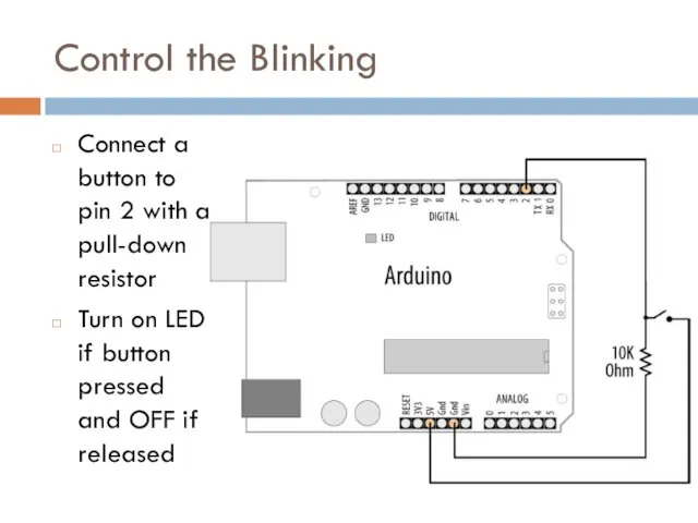
- 10. Control the Blinking Connect a button to pin 2 with a pull-down resistor Turn on LED
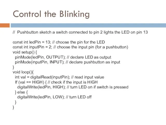
- 11. Control the Blinking // Pushbutton sketch a switch connected to pin 2 lights the LED on
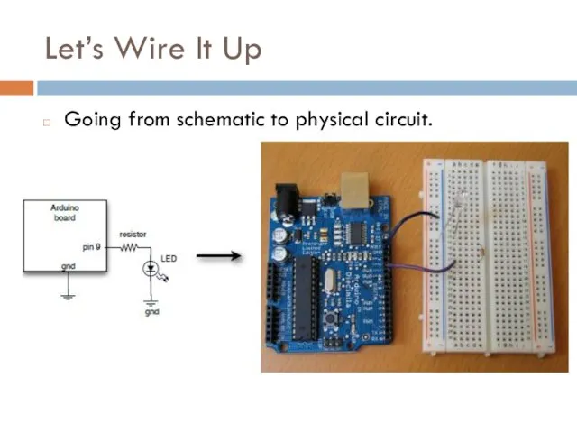
- 12. Let’s Wire It Up Going from schematic to physical circuit.
- 13. Solderless Breadboards
- 14. Useful Tools
- 15. Making Jumper Wires
- 16. Using Solderless Breadboards Using needle nose pliers can help push wires & components into holes
- 17. All Wired Up
- 18. Using Switches to Make Decisions Often you’ll want to choose between actions, based on a data
- 19. Control the Blinking (pull-up)
- 20. Switch Without External Resistors Arduino has internal pull-up resistors that can be enabled by writing a
- 21. Reliably Detecting the Switch State contact bounce produces spurious signals at the moment the switch contacts
- 22. Analog Input To computers, analog is chunky
- 23. Analog Input Many states, not just two (HIGH/LOW) Number of states (or values, or “bins”) is
- 24. Analog Input Arduino (ATmega168) has six ADC inputs (ADC = Analog to Digital Converter) Reads voltage
- 25. Analog Input Sure sure, but how to make a varying voltage? With a potentiometer. (pot)
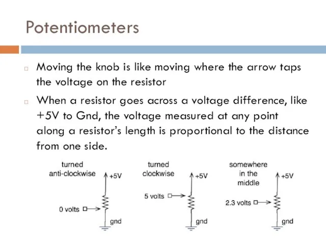
- 26. Potentiometers Moving the knob is like moving where the arrow taps the voltage on the resistor
- 27. What good are pots at? Anytime you need a ranged input Measure rotational position steering wheel,
- 28. Arduino Analog Input Plug pot directly into breadboard Two “legs” plug into +5V & Gnd (red
- 29. Pot & LED Circuit
- 31. Скачать презентацию
Simple Digital and Analog Inputs
The Arduino’s ability to sense digital and
Simple Digital and Analog Inputs
The Arduino’s ability to sense digital and
Simple Digital and Analog Inputs
digitalRead(pin) - tells your sketch if a
Simple Digital and Analog Inputs
digitalRead(pin) - tells your sketch if a
Simple Digital and Analog Inputs
Still need more?
Analog pins 0 through 15
Simple Digital and Analog Inputs
Still need more?
Analog pins 0 through 15
Sensors & Inputs
Many sensors are variations on switches
Switches make or break
Sensors & Inputs
Many sensors are variations on switches
Switches make or break
Many Kinds of Switches
Tilt sensor has a little ball inside
Magnetic switches
Many Kinds of Switches
Tilt sensor has a little ball inside
Magnetic switches
Digital Input
Switches make or break a connection
But Arduino wants to see
Digital Input
Switches make or break a connection
But Arduino wants to see
From Switch to HIGH / LOW
With no connection, digital inputs “float”
From Switch to HIGH / LOW
With no connection, digital inputs “float”
Pull-up and Pull-down
pull-up resistors – pull the voltage up to the
Pull-up and Pull-down
pull-up resistors – pull the voltage up to the
Control the Blinking
Connect a button to pin 2 with a pull-down
Control the Blinking
Connect a button to pin 2 with a pull-down
Control the Blinking
// Pushbutton sketch a switch connected to pin 2
Control the Blinking
// Pushbutton sketch a switch connected to pin 2
Let’s Wire It Up
Going from schematic to physical circuit.
Let’s Wire It Up
Going from schematic to physical circuit.
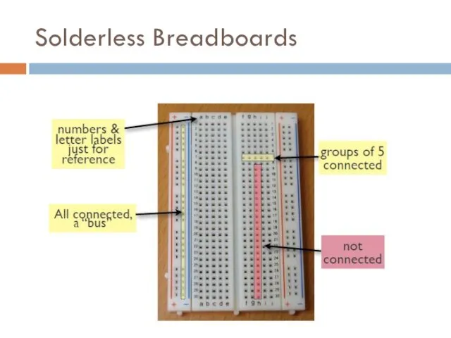
Solderless Breadboards
Solderless Breadboards
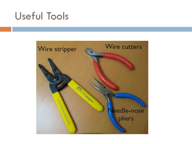
Useful Tools
Useful Tools
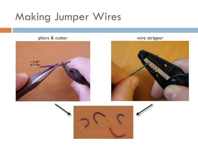
Making Jumper Wires
Making Jumper Wires
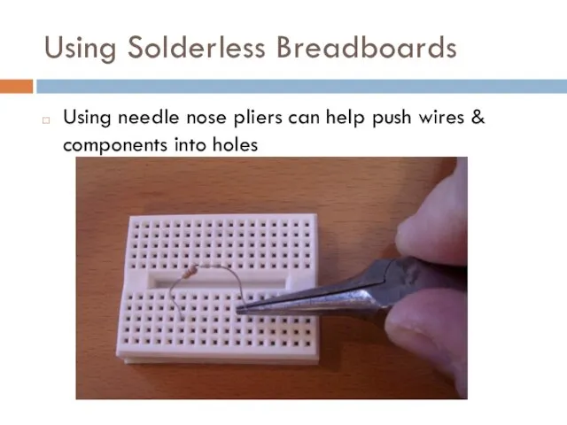
Using Solderless Breadboards
Using needle nose pliers can help push wires &
Using Solderless Breadboards
Using needle nose pliers can help push wires &
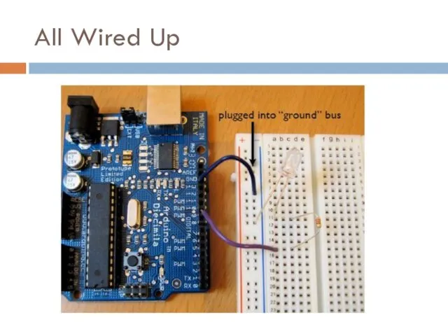
All Wired Up
All Wired Up
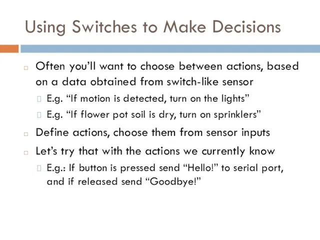
Using Switches to Make Decisions
Often you’ll want to choose between actions,
Using Switches to Make Decisions
Often you’ll want to choose between actions,
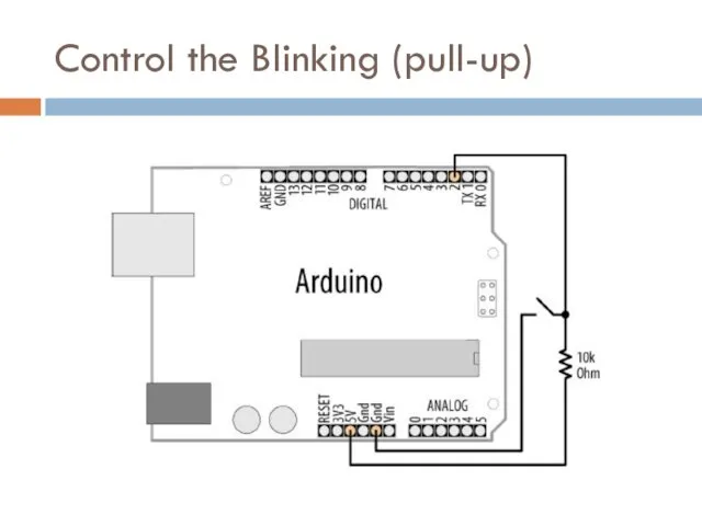
Control the Blinking (pull-up)
Control the Blinking (pull-up)
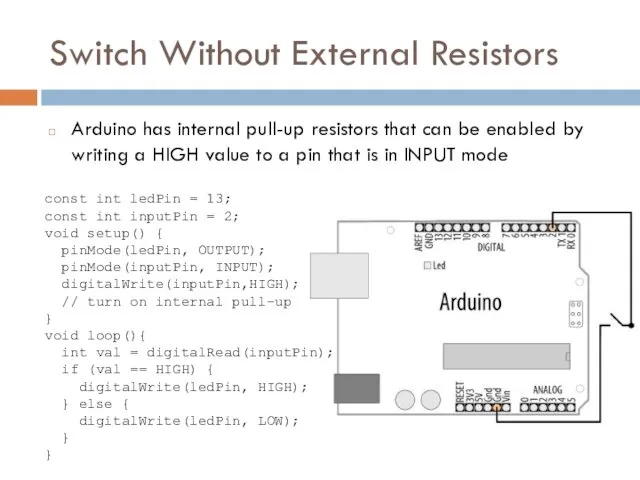
Switch Without External Resistors
Arduino has internal pull-up resistors that can be
Switch Without External Resistors
Arduino has internal pull-up resistors that can be
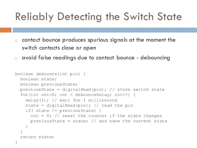
Reliably Detecting the Switch State
contact bounce produces spurious signals at the
Reliably Detecting the Switch State
contact bounce produces spurious signals at the
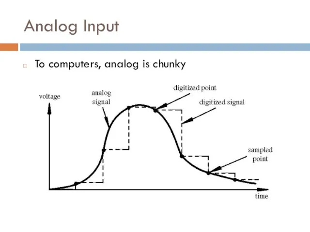
Analog Input
To computers, analog is chunky
Analog Input
To computers, analog is chunky
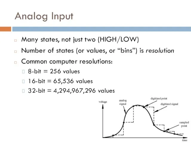
Analog Input
Many states, not just two (HIGH/LOW)
Number of states (or values,
Analog Input
Many states, not just two (HIGH/LOW)
Number of states (or values,
Analog Input
Arduino (ATmega168) has six ADC inputs
(ADC = Analog to Digital
Analog Input
Arduino (ATmega168) has six ADC inputs
(ADC = Analog to Digital
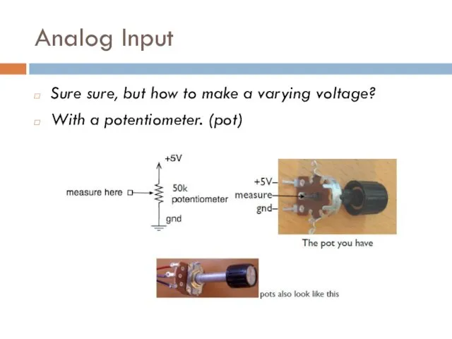
Analog Input
Sure sure, but how to make a varying voltage?
With a
Analog Input
Sure sure, but how to make a varying voltage?
With a
Potentiometers
Moving the knob is like moving where the arrow taps the
Potentiometers
Moving the knob is like moving where the arrow taps the
What good are pots at?
Anytime you need a ranged input
Measure rotational
What good are pots at?
Anytime you need a ranged input
Measure rotational
Arduino Analog Input
Plug pot directly into breadboard
Two “legs” plug into +5V
Arduino Analog Input
Plug pot directly into breadboard
Two “legs” plug into +5V
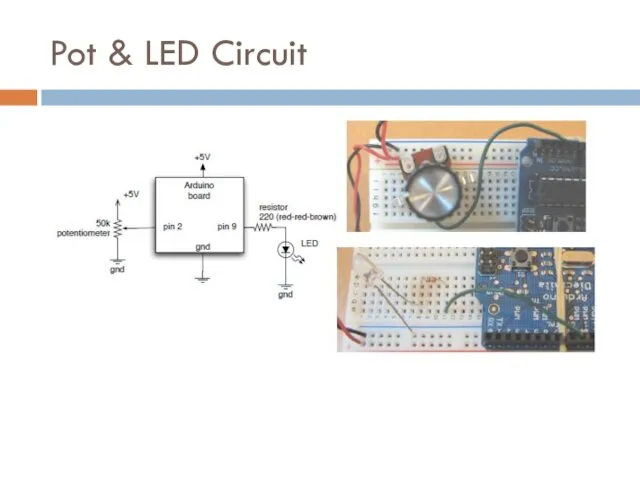
Pot & LED Circuit
Pot & LED Circuit
 Физиология голоса
 Презентация Наше веселое лето
 Система крови. Состав и функция крови. Кровь и её компоненты
 Обновление содержания общего образования в РФ
 Особенности перемещения через таможенную границу и совершения таможенных операций в отношении водных биоресурсов
 Урок-размышление по рассказу Федора Абрамова О чем плачут лошади
 Ричард Докинз и его открытия в области генетики
 Н. Сладков. Лисица и Ёж
 Способы обозначения звука [й] в разных позициях
 У войны не женское лицо (фотографии)
 Сомообразование педагогов в ДОУ
 Защита информации. Компьютерные вирусы и антивирусные программы
 Как заставить себя учиться
 История клинической психологии
 Презентация День культуры и вежливости
 Функциональная анатомия соединений костей туловища
 Субкультура-это… Субкультура рок-металла…
 Урок географии по теме Воды суши. Реки.
 Материаловедение. Основы литейного производства. (Тема 10)
 Адгезивные системы (материалы на основе корневых адгезивов)
 Влажно-тепловая обработка деталей
 Компания Toyota Motor Corporation
 Система нормативных правовых актов, регулирующих правовое положение крестьянского (фермерского) хозяйства
 Карбоновые кислоты
 Презентация к уроку Численность и воспроизводство населения (10 класс)
 Вырасти чудо-цветок своими руками
 Листовая продукция
 Общие пути биологического окисления