- Single screw compressor presentation. Working principle & inspection guidelines

Содержание
- 2. Daikin Single G-type Screw Compressor G - Type Single Screw R134a Up to 90 KW120 Hp
- 3. Stepless Single Screw Compressor History F-type G-type G-type stepless 2005 2003 2000 time Robustness, reliability =
- 4. G type compressor Nomenclature G, G4 = step GU,G5, G6 =Stepless 3-5-7-9 sizes
- 5. G type compressor with step control G-type step range from 30KW to 135 KW
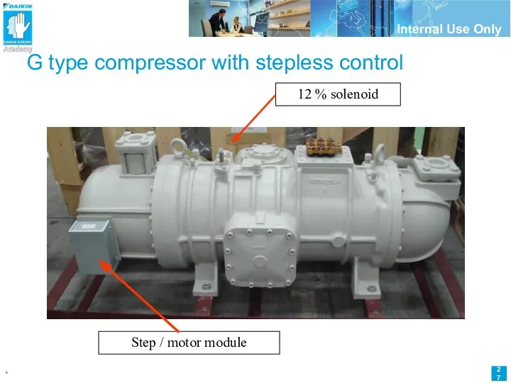
- 6. G type compressor with stepless control G-type stepless range from 30KW to 135 KW
- 7. The single, mono or globoïd screw Closed end Open end Satelite Or Gate Rotor = Special
- 8. Gate rotor and gate rotorshaft
- 9. The G-type screw compressor Motor & suction section Compression section Oil separator & capacitycontrol
- 10. The Heart of the single screw compressor Motor & suction section Compression section Oil separator &
- 11. The flow inside compressor
- 12. Compression Principle
- 13. G-type screwcompressor Compression principle
- 14. Capacity adjustment design Loading & Unloading Mechanism G types until 2005 step control 3 to 4
- 15. Capacity adjustment design step Step control Principle Is based on internal pressure differences Selection of capacity
- 16. step control/essential parts Capacity solenoid valves 12 12
- 17. step control/essential parts Sliding vanes with bridge and springs
- 18. step control/essential parts Slide vane bridge with capacity cylinder/piston
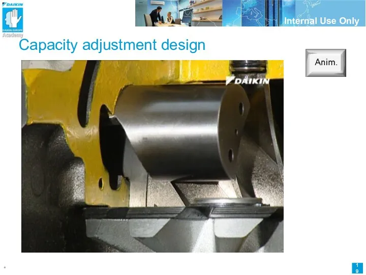
- 19. Capacity adjustment design
- 20. SV1=12% SV2=40% SV3=70% Step control system Energized = open ! Spacer Low pressure side Screw rotor
- 21. Compressor start Compressor loads-up to 40% SV1 closes = de-energized 12% capacity Hi press Low press.
- 22. Compressor loads-up to 70% SV1 and 2 close = de-energized 40% capacity Hi press Low press.
- 23. Compressor loads-up to 100% SV1,2 and 3 close = de-energized 70% capacity Low press. side
- 24. Full Load = All solenoid valves are de-energized ! Full travel approx. 4cm Low press. side
- 25. Capacity adjustment design stepLESS Stepless control Principle Is based on internal pressure differences Regulation of stepless
- 26. Stepless Single Screw Compressor STEPLESS capacity regulation Designed, tested and manufactured in Daikin’s own laboratories. Higher
- 27. G type compressor with stepless control Step / motor module 12 % solenoid
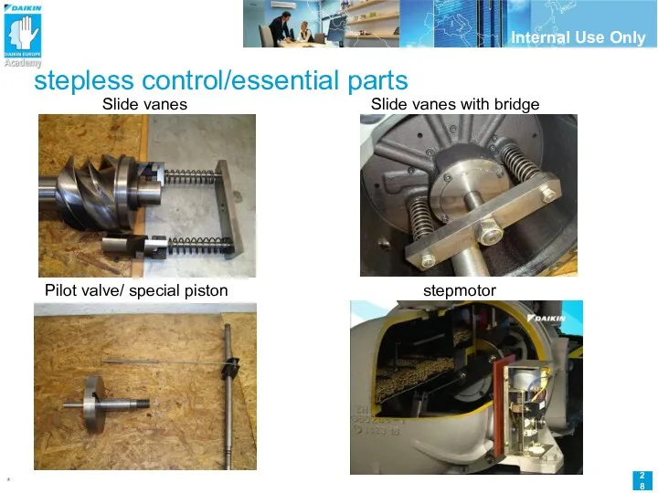
- 28. stepless control/essential parts Slide vanes Slide vanes with bridge Pilot valve/ special piston stepmotor
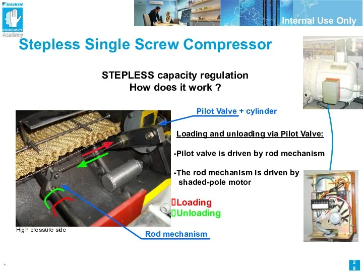
- 29. Stepless Single Screw Compressor STEPLESS capacity regulation How does it work ? Loading and unloading via
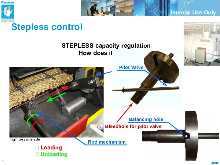
- 30. Stepless control STEPLESS capacity regulation How does it work ? Rod mechanism High pressure side Pilot
- 31. Stepless regulation/pressure difference HP (High Pressure) Main screw Sliding Vane Load/unload mechanism Piston HP HP Spring
- 32. Stepless Single Screw Compressor HP (High Pressure) Low Pressure Gate rotor Main screw Sliding Vane Load/unload
- 33. Stepless Single Screw Compressor @ 100% Position of pilot vane moves to right side (towards 90%)
- 34. Stepless Single Screw Compressor @ 95% Low Pressure HP HP Low Pressure dHP dHP HP Bigger
- 35. Stepless Single Screw Compressor @ 90% Low Pressure HP HP Low Pressure Small bleed Towards LP-side
- 36. Stepless Single Screw Compressor @ start Low Pressure HP HP Low Pressure bleed DP Towards LP-side
- 37. Stepless Single Screw Compressor 12 % 30% Upload possible 0 % 20 s 40 s 120
- 38. Stepless Single Screw Compressor z Position of PILOT VALVE moves RIGHT Position of PILOT VALVE moves
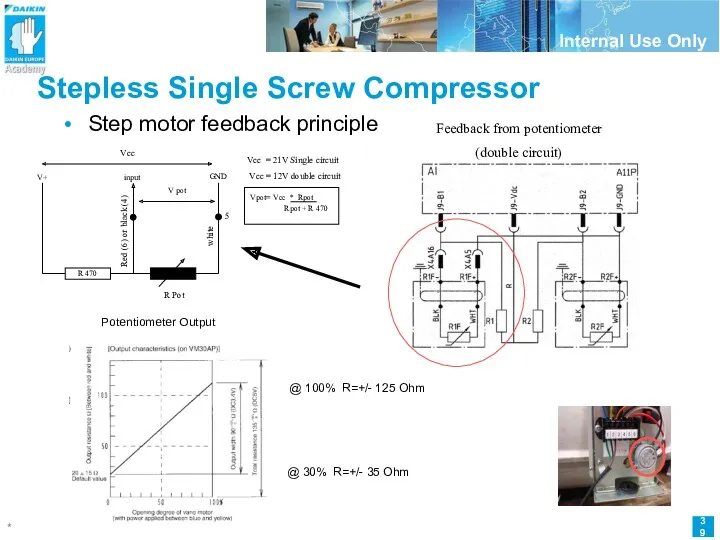
- 39. Stepless Single Screw Compressor Step motor feedback principle Feedback from potentiometer (double circuit) R 470 R
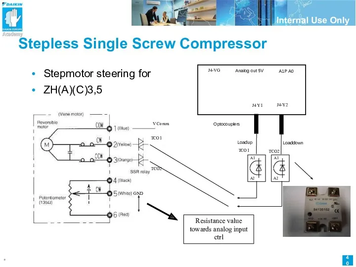
- 40. Stepless Single Screw Compressor Stepmotor steering for ZH(A)(C)3,5 TCO1 TCO2 J4-VG J4 Y1 J4-Y2 TCO1 TCO2
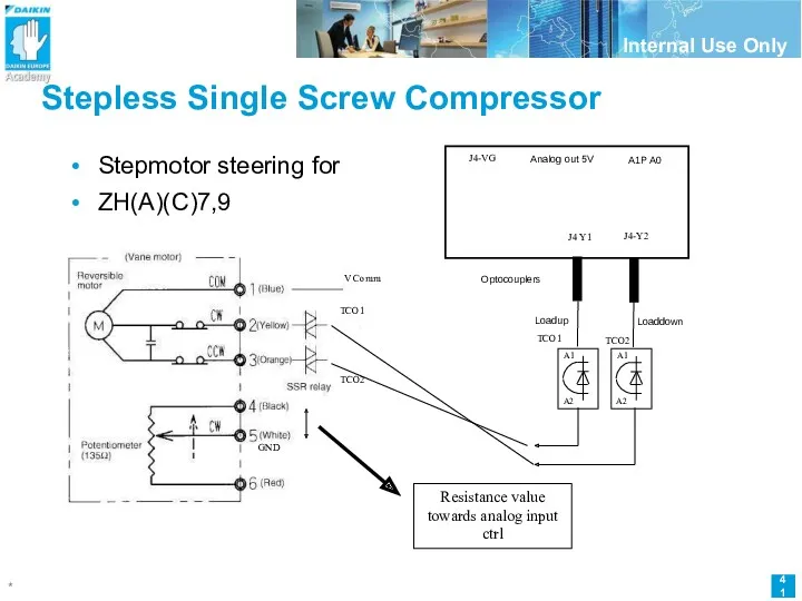
- 41. Stepless Single Screw Compressor Stepmotor steering for ZH(A)(C)7,9 TCO1 TCO2 J4-VG J4 Y1 J4-Y2 TCO1 TCO2
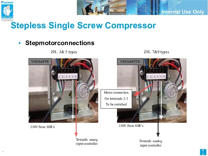
- 42. Stepless Single Screw Compressor Stepmotorconnections ZH.. 7&9 types ZH.. 3& 5 types Towards anaog input controller
- 43. Oil and Liquid injection design Seals Cools Lubricates Reduces sound Simplified oil management Single screw compressor
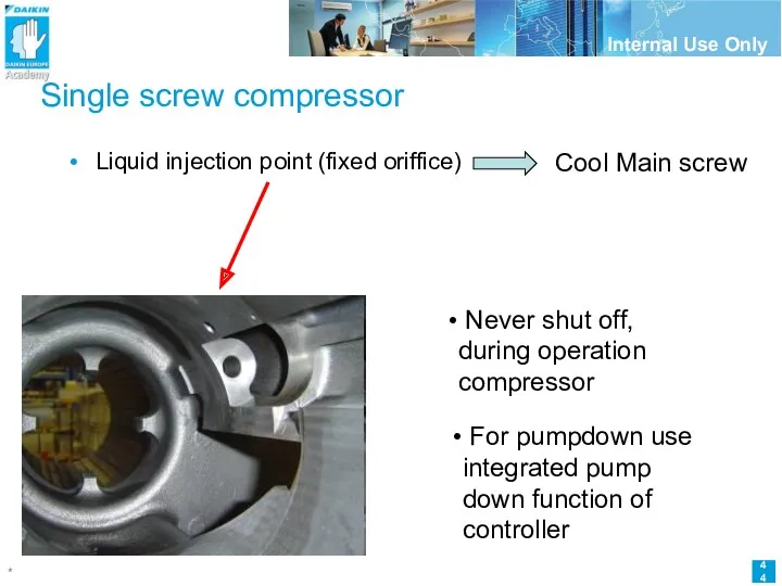
- 44. Single screw compressor Liquid injection point (fixed oriffice) Cool Main screw Never shut off, during operation
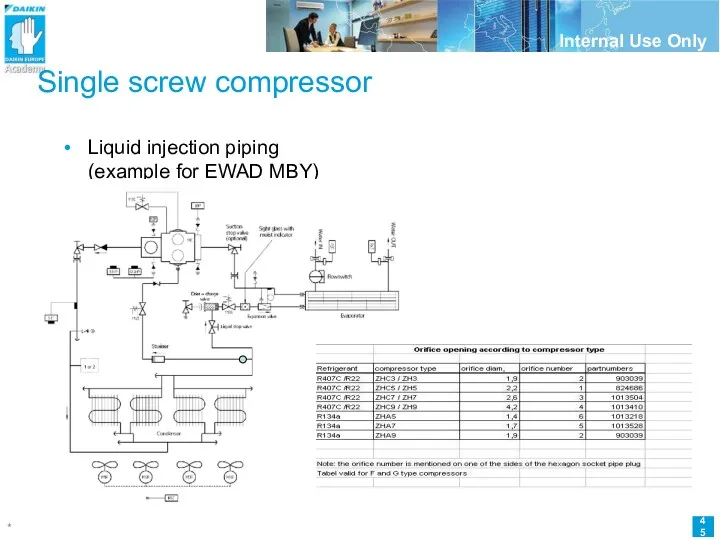
- 45. Single screw compressor Liquid injection piping (example for EWAD MBY)
- 46. Single screw compressor Periodic Inspection
- 47. Single screw compressor - Inspection Periodic Inspection - Check points Insulation Resistance of the Motor. Inspection/Changement
- 48. Single screw compressor - Inspection Check points Insulation Resistance of the Motor. After 1year of operation.
- 49. Single screw compressor - Inspection Check points Inspection/Changement of the Refrigerant Oil. Take a oil sample
- 50. Single screw compressor - Inspection Oil drain ports
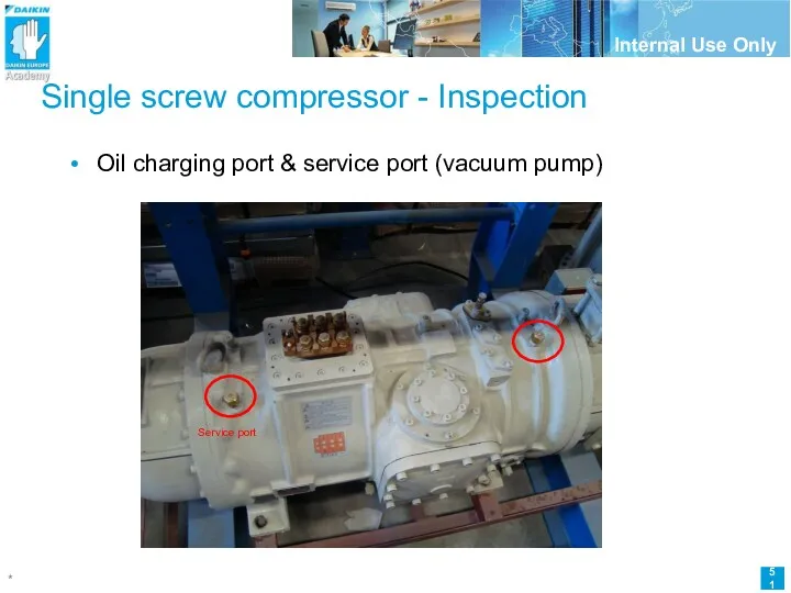
- 51. Single screw compressor - Inspection Oil charging port & service port (vacuum pump) Service port
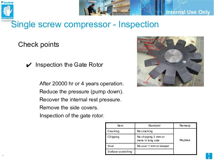
- 52. Single screw compressor - Inspection Check points Inspection the Gate Rotor After 20000 hr or 4
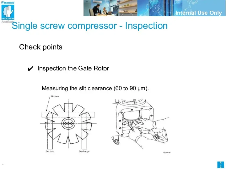
- 53. Single screw compressor - Inspection Check points Inspection the Gate Rotor Measuring the slit clearance (60
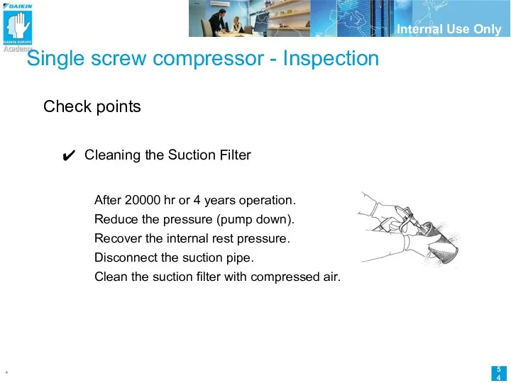
- 54. Single screw compressor - Inspection Check points Cleaning the Suction Filter After 20000 hr or 4
- 55. Single screw compressor Overhaul
- 56. Low Maintenance Costs Only three rotating parts ...
- 57. Low Maintenance Costs … and two sliding parts NO O-rings NO gaskets NO Oilpump
- 58. Single Screw Compressor - Overhaul Overhaul (see service manual Si50-402A) Overhaul interval:40.000 hrs or 7 years,
- 59. Single Screw Compressor - Overhaul Overhaul Instructions Chart (See Service Manual SiE50-402A) 1. Disassembly and Inspection
- 60. Single Screw Compressor - Overhaul Overhaul Instructions Chart(See Service Manual SiE50-402A) 2. Replacing The Bearing Remove
- 61. Single Screw Compressor - Overhaul Overhaul Instructions Chart (See Service Manual SiE50-402A) 3. Final Assembly Assemble
- 62. Single Screw Compressor - Overhaul Overhaul Instructions Chart (See Service Manual SiE50-402a) 4. Airtightness Test Using
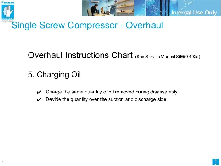
- 63. Single Screw Compressor - Overhaul Overhaul Instructions Chart (See Service Manual SiE50-402a) 5. Charging Oil Charge
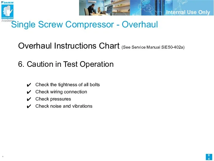
- 64. Single Screw Compressor - Overhaul Overhaul Instructions Chart (See Service Manual SiE50-402a) 6. Caution in Test
- 65. Single Screw Compressor – Overhaul pics
- 67. Скачать презентацию
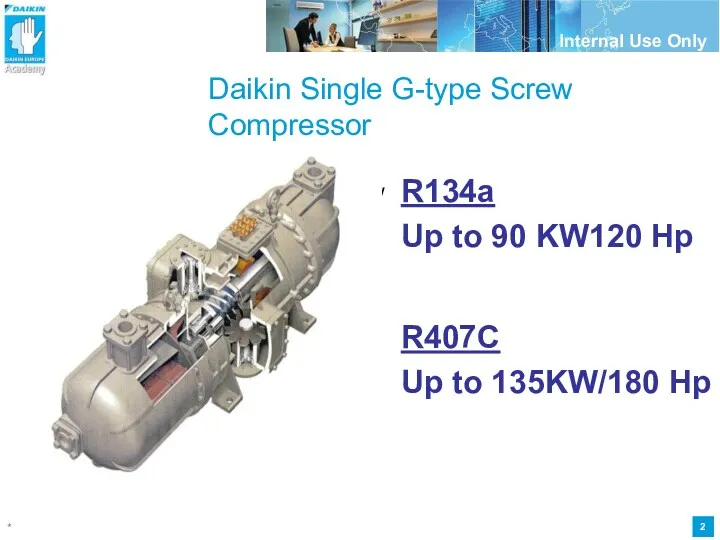
Daikin Single G-type Screw Compressor
G - Type Single Screw
R134a
Up to
Daikin Single G-type Screw Compressor
G - Type Single Screw
R134a
Up to

Stepless Single Screw Compressor
History
F-type
G-type
G-type stepless
2005
2003
2000
time
Robustness, reliability = Robustness, reliability
Performance
Stepless Single Screw Compressor
History
F-type
G-type
G-type stepless
2005
2003
2000
time
Robustness, reliability = Robustness, reliability
Performance
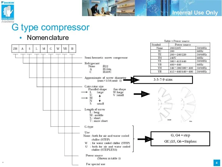
G type compressor
Nomenclature
G, G4 = step
GU,G5, G6 =Stepless
3-5-7-9 sizes
G type compressor
Nomenclature
G, G4 = step
GU,G5, G6 =Stepless
3-5-7-9 sizes
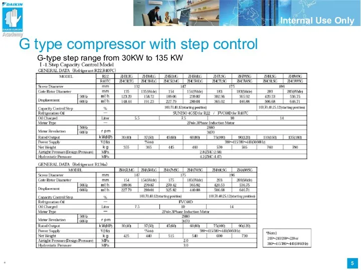
G type compressor with step control
G-type step range from 30KW
G type compressor with step control
G-type step range from 30KW
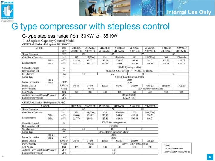
G type compressor with stepless control
G-type stepless range from 30KW
G type compressor with stepless control
G-type stepless range from 30KW
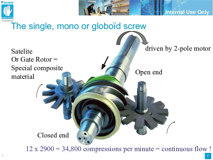
The single, mono or globoïd screw
Closed end
Open end
Satelite
Or Gate Rotor =
The single, mono or globoïd screw
Closed end
Open end
Satelite
Or Gate Rotor =
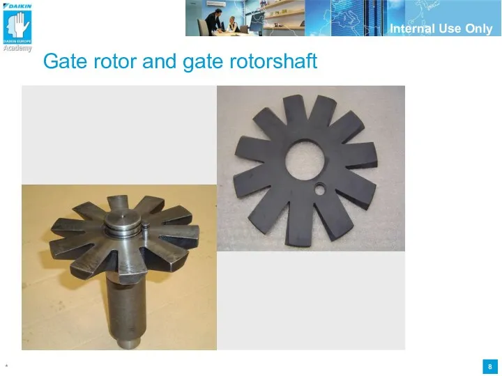
Gate rotor and gate rotorshaft
Gate rotor and gate rotorshaft
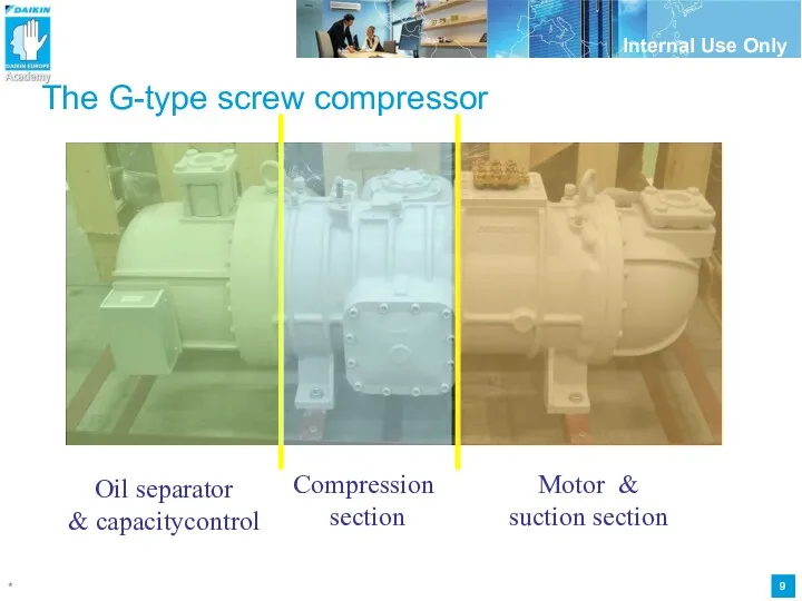
The G-type screw compressor
Motor & suction section
Compression
section
Oil separator
& capacitycontrol
The G-type screw compressor
Motor & suction section
Compression
section
Oil separator
& capacitycontrol
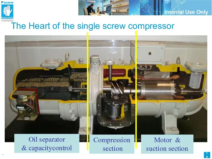
The Heart of the single screw compressor
Motor & suction section
Compression
section
Oil
The Heart of the single screw compressor
Motor & suction section
Compression
section
Oil
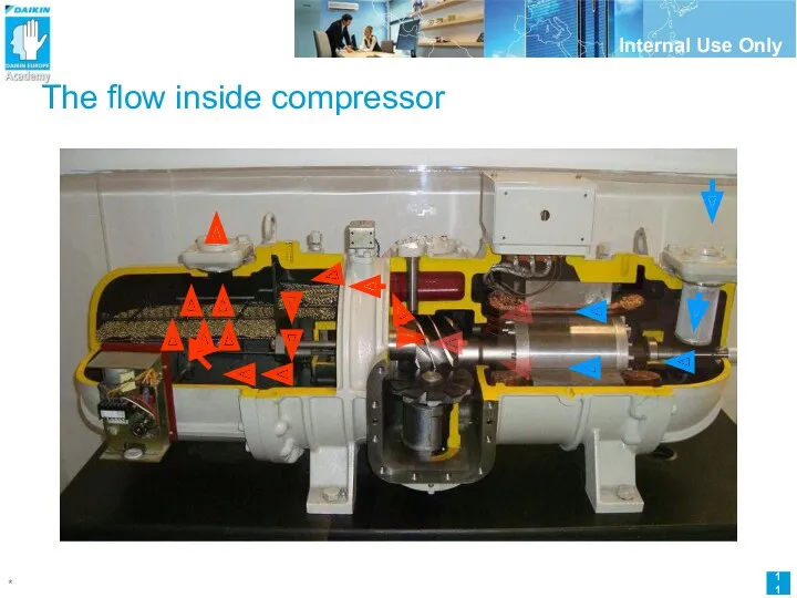
The flow inside compressor
The flow inside compressor
Compression
Principle
Compression
Principle
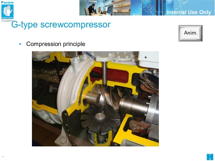
G-type screwcompressor
Compression principle
G-type screwcompressor
Compression principle
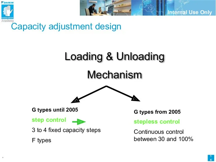
Capacity adjustment design
Loading & Unloading
Mechanism
G types until 2005
step control
3 to
Capacity adjustment design
Loading & Unloading
Mechanism
G types until 2005
step control
3 to
Capacity adjustment design step
Step control
Principle
Is based on internal pressure differences
Selection of
Capacity adjustment design step
Step control
Principle
Is based on internal pressure differences
Selection of
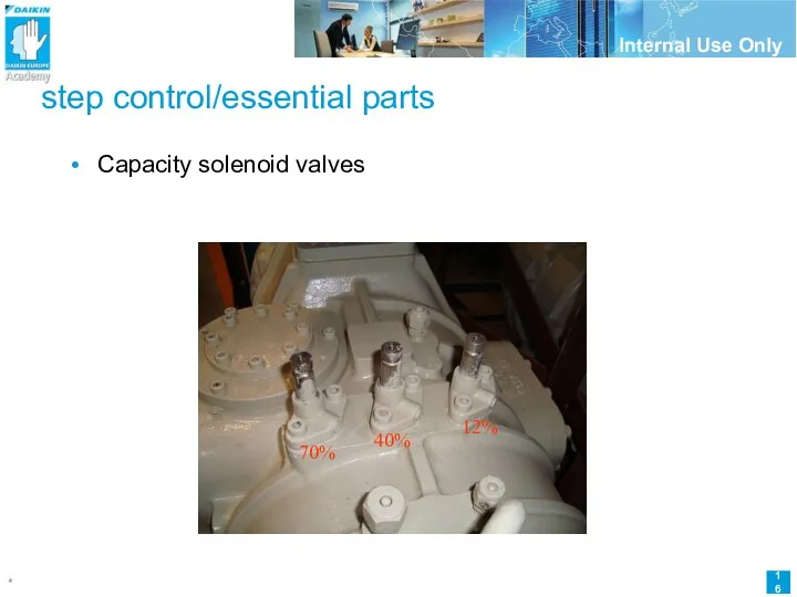
step control/essential parts
Capacity solenoid valves
12
12
step control/essential parts
Capacity solenoid valves
12
12
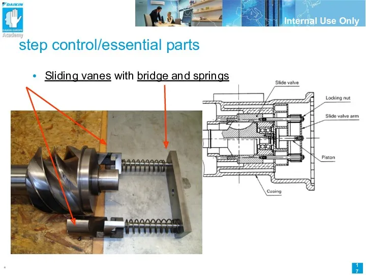
step control/essential parts
Sliding vanes with bridge and springs
step control/essential parts
Sliding vanes with bridge and springs
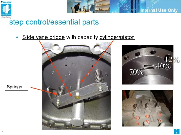
step control/essential parts
Slide vane bridge with capacity cylinder/piston
step control/essential parts
Slide vane bridge with capacity cylinder/piston
Capacity adjustment design
Capacity adjustment design
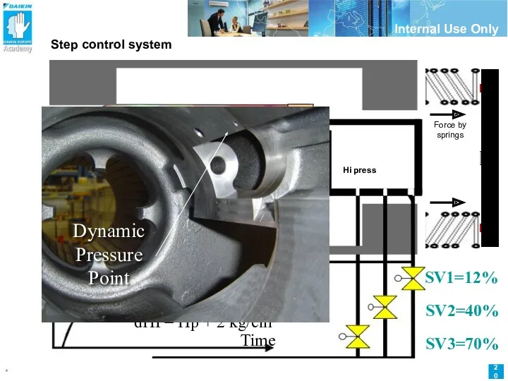
SV1=12%
SV2=40%
SV3=70%
Step control system
Energized = open !
Spacer
Low pressure side
Screw rotor
Dynamic
pressure
point
Hi press
Force by
SV1=12%
SV2=40%
SV3=70%
Step control system
Energized = open !
Spacer
Low pressure side
Screw rotor
Dynamic
pressure
point
Hi press
Force by
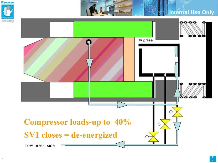
Compressor start
Compressor loads-up to 40%
SV1 closes = de-energized
12%
capacity
Hi press
Low press.
Compressor start
Compressor loads-up to 40%
SV1 closes = de-energized
12%
capacity
Hi press
Low press.
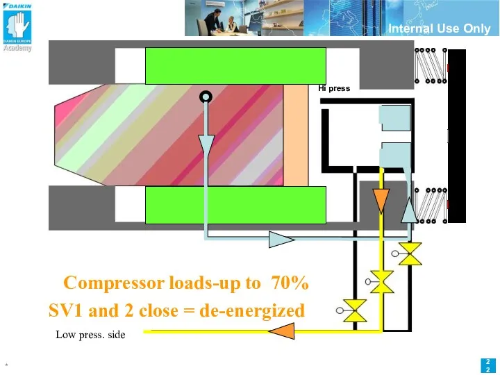
Compressor loads-up to 70%
SV1 and 2 close = de-energized
40%
capacity
Hi press
Low
Compressor loads-up to 70%
SV1 and 2 close = de-energized
40%
capacity
Hi press
Low
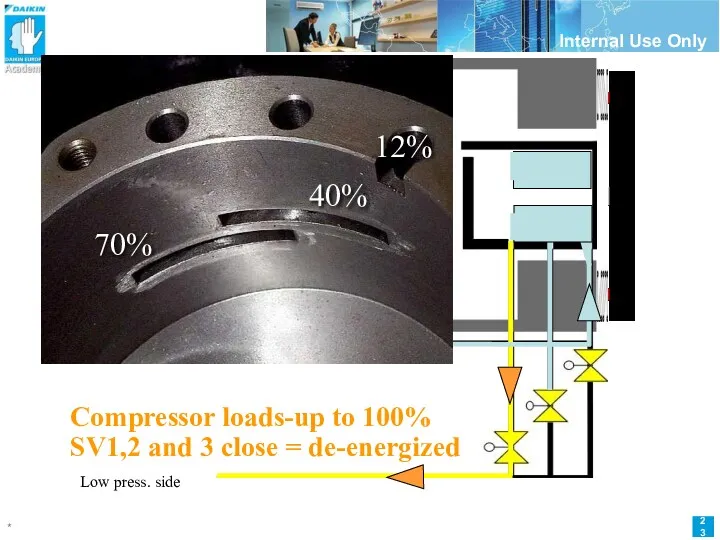
Compressor loads-up to 100%
SV1,2 and 3 close = de-energized
70%
capacity
Low press.
Compressor loads-up to 100%
SV1,2 and 3 close = de-energized
70%
capacity
Low press.
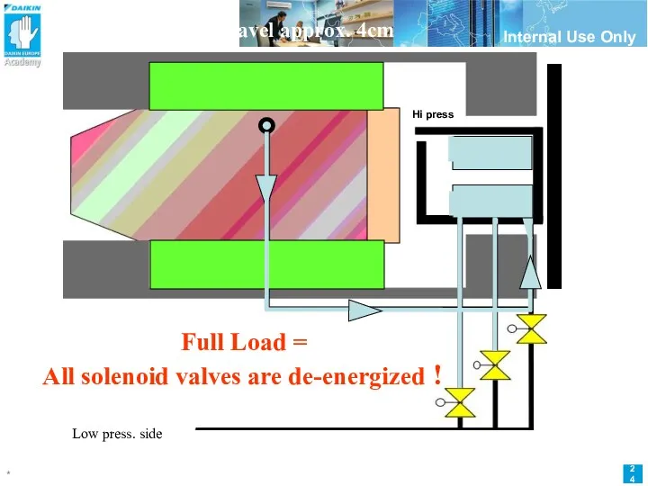
Full Load =
All solenoid valves are de-energized !
Full travel approx. 4cm
Low
Full Load =
All solenoid valves are de-energized !
Full travel approx. 4cm
Low
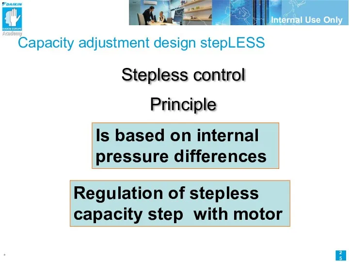
Capacity adjustment design stepLESS
Stepless control
Principle
Is based on internal pressure differences
Regulation of
Capacity adjustment design stepLESS
Stepless control
Principle
Is based on internal pressure differences
Regulation of
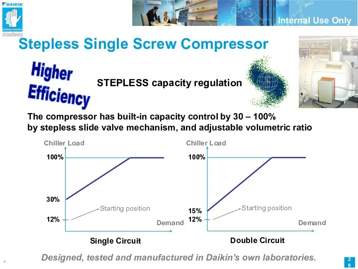
Stepless Single Screw Compressor
STEPLESS capacity regulation
Designed, tested and manufactured in Daikin’s
Stepless Single Screw Compressor
STEPLESS capacity regulation
Designed, tested and manufactured in Daikin’s
G type compressor with stepless control
Step / motor module
12 % solenoid
G type compressor with stepless control
Step / motor module
12 % solenoid
stepless control/essential parts
Slide vanes
Slide vanes with bridge
Pilot valve/ special piston
stepmotor
stepless control/essential parts
Slide vanes
Slide vanes with bridge
Pilot valve/ special piston
stepmotor
Stepless Single Screw Compressor
STEPLESS capacity regulation
How does it work ?
Loading and
Stepless Single Screw Compressor
STEPLESS capacity regulation
How does it work ?
Loading and
Stepless control
STEPLESS capacity regulation
How does it work ?
Rod mechanism
High pressure side
Pilot
Stepless control
STEPLESS capacity regulation
How does it work ?
Rod mechanism
High pressure side
Pilot
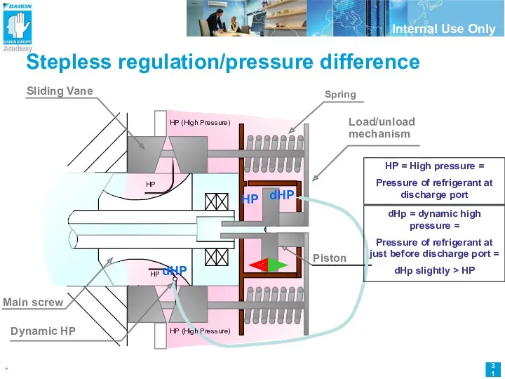
Stepless regulation/pressure difference
HP (High Pressure)
Main screw
Sliding Vane
Load/unload
mechanism
Piston
HP
HP
Spring
HP (High Pressure)
Dynamic
Stepless regulation/pressure difference
HP (High Pressure)
Main screw
Sliding Vane
Load/unload
mechanism
Piston
HP
HP
Spring
HP (High Pressure)
Dynamic
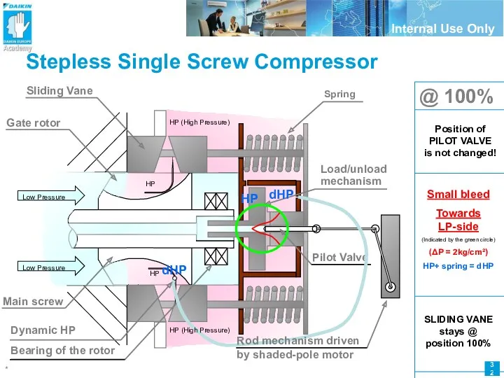
Stepless Single Screw Compressor
HP (High Pressure)
Low Pressure
Gate rotor
Main screw
Sliding Vane
Load/unload
Stepless Single Screw Compressor
HP (High Pressure)
Low Pressure
Gate rotor
Main screw
Sliding Vane
Load/unload
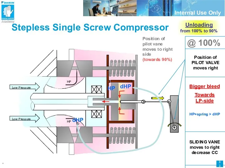
Stepless Single Screw Compressor
@ 100%
Position of
pilot vane moves to right
Stepless Single Screw Compressor
@ 100%
Position of
pilot vane moves to right
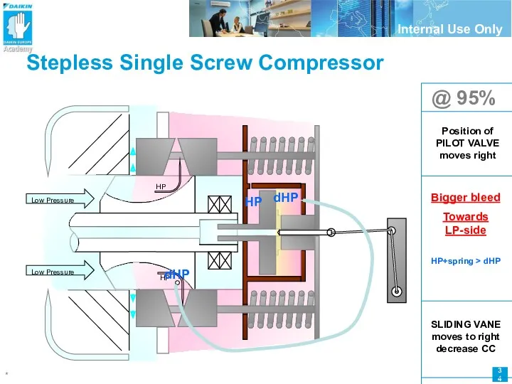
Stepless Single Screw Compressor
@ 95%
Low Pressure
HP
HP
Low Pressure
dHP
dHP
HP
Bigger bleed
Towards LP-side
HP+spring
Stepless Single Screw Compressor
@ 95%
Low Pressure
HP
HP
Low Pressure
dHP
dHP
HP
Bigger bleed
Towards LP-side
HP+spring
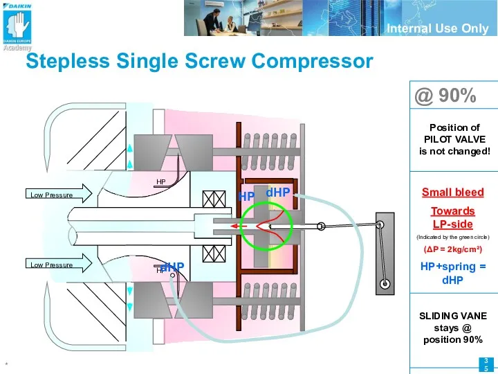
Stepless Single Screw Compressor
@ 90%
Low Pressure
HP
HP
Low Pressure
Small bleed
Towards LP-side
(Indicated
Stepless Single Screw Compressor
@ 90%
Low Pressure
HP
HP
Low Pressure
Small bleed
Towards LP-side
(Indicated
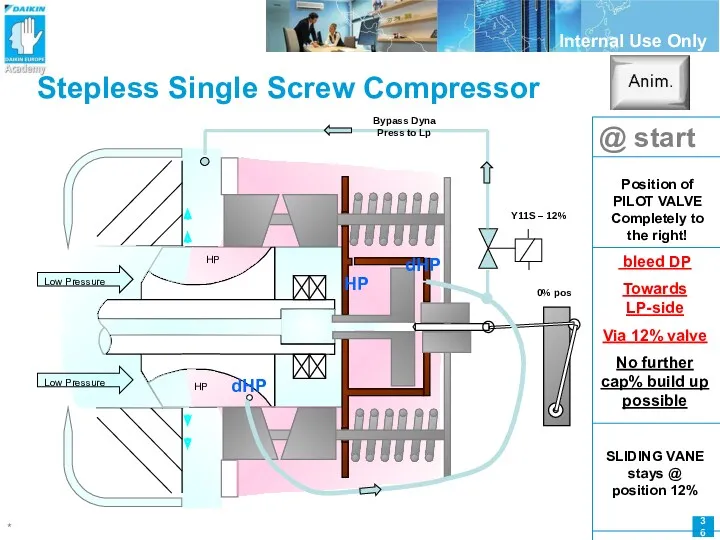
Stepless Single Screw Compressor
@ start
Low Pressure
HP
HP
Low Pressure
bleed DP
Towards
Stepless Single Screw Compressor
@ start
Low Pressure
HP
HP
Low Pressure
bleed DP
Towards
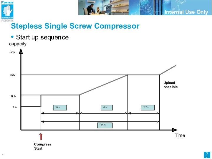
Stepless Single Screw Compressor
12 %
30%
Upload possible
0 %
20 s
40 s
120 s
180 S
capacity
Time
Compress
Stepless Single Screw Compressor
12 %
30%
Upload possible
0 %
20 s
40 s
120 s
180 S
capacity
Time
Compress
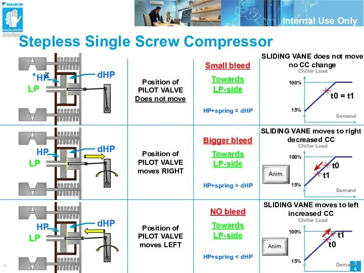
Stepless Single Screw Compressor
z
Position of
PILOT VALVE
moves RIGHT
Position of
PILOT
Stepless Single Screw Compressor
z
Position of
PILOT VALVE
moves RIGHT
Position of
PILOT
Stepless Single Screw Compressor
Step motor feedback principle
Feedback from potentiometer
(double circuit)
R 470
R
Stepless Single Screw Compressor
Step motor feedback principle
Feedback from potentiometer
(double circuit)
R 470
R
Stepless Single Screw Compressor
Stepmotor steering for
ZH(A)(C)3,5
TCO1
TCO2
J4-VG
J4 Y1
J4-Y2
TCO1
TCO2
Optocouplers
Analog out 5V
A1P A0
Loadup
Loaddown
V
Stepless Single Screw Compressor
Stepmotor steering for
ZH(A)(C)3,5
TCO1
TCO2
J4-VG
J4 Y1
J4-Y2
TCO1
TCO2
Optocouplers
Analog out 5V
A1P A0
Loadup
Loaddown
V
Stepless Single Screw Compressor
Stepmotor steering for
ZH(A)(C)7,9
TCO1
TCO2
J4-VG
J4 Y1
J4-Y2
TCO1
TCO2
Optocouplers
Analog out 5V
A1P A0
Loadup
Loaddown
V
Stepless Single Screw Compressor
Stepmotor steering for
ZH(A)(C)7,9
TCO1
TCO2
J4-VG
J4 Y1
J4-Y2
TCO1
TCO2
Optocouplers
Analog out 5V
A1P A0
Loadup
Loaddown
V
Stepless Single Screw Compressor
Stepmotorconnections
ZH.. 7&9 types
ZH.. 3& 5 types
Towards
Stepless Single Screw Compressor
Stepmotorconnections
ZH.. 7&9 types
ZH.. 3& 5 types
Towards
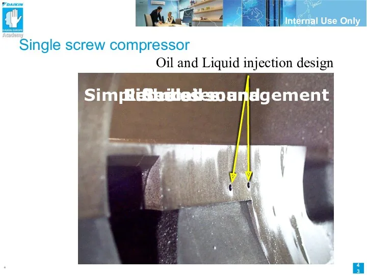
Oil and Liquid injection design
Seals
Cools
Lubricates
Reduces sound
Simplified oil management
Single screw compressor
Oil and Liquid injection design
Seals
Cools
Lubricates
Reduces sound
Simplified oil management
Single screw compressor
Single screw compressor
Liquid injection point (fixed oriffice)
Cool Main screw
Never
Single screw compressor
Liquid injection point (fixed oriffice)
Cool Main screw
Never
Single screw compressor
Liquid injection piping (example for EWAD MBY)
Single screw compressor
Liquid injection piping (example for EWAD MBY)
Single screw compressor
Periodic Inspection
Single screw compressor
Periodic Inspection
Single screw compressor - Inspection
Periodic Inspection - Check points
Insulation Resistance of
Single screw compressor - Inspection
Periodic Inspection - Check points
Insulation Resistance of
Single screw compressor - Inspection
Check points
Insulation Resistance of the Motor.
After 1year
Single screw compressor - Inspection
Check points
Insulation Resistance of the Motor.
After 1year
Single screw compressor - Inspection
Check points
Inspection/Changement of the Refrigerant Oil.
Take a
Single screw compressor - Inspection
Check points
Inspection/Changement of the Refrigerant Oil.
Take a
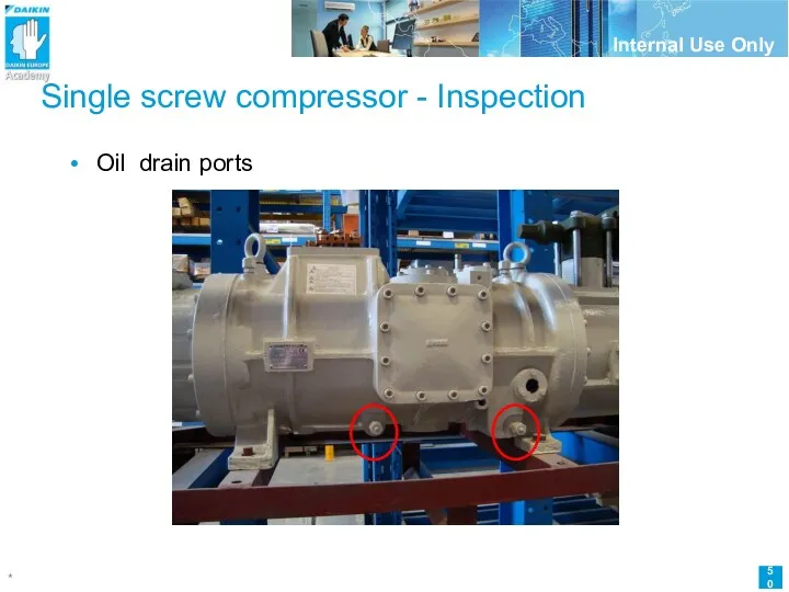
Single screw compressor - Inspection
Oil drain ports
Single screw compressor - Inspection
Oil drain ports
Single screw compressor - Inspection
Oil charging port & service port (vacuum
Single screw compressor - Inspection
Oil charging port & service port (vacuum
Single screw compressor - Inspection
Check points
Inspection the Gate Rotor
After 20000 hr
Single screw compressor - Inspection
Check points
Inspection the Gate Rotor
After 20000 hr
Single screw compressor - Inspection
Check points
Inspection the Gate Rotor
Measuring the slit
Single screw compressor - Inspection
Check points
Inspection the Gate Rotor
Measuring the slit
Single screw compressor - Inspection
Check points
Cleaning the Suction Filter
After 20000 hr
Single screw compressor - Inspection
Check points
Cleaning the Suction Filter
After 20000 hr
Single screw compressor
Overhaul
Single screw compressor
Overhaul
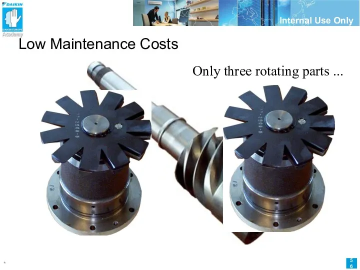
Low Maintenance Costs
Only three rotating parts ...
Low Maintenance Costs
Only three rotating parts ...
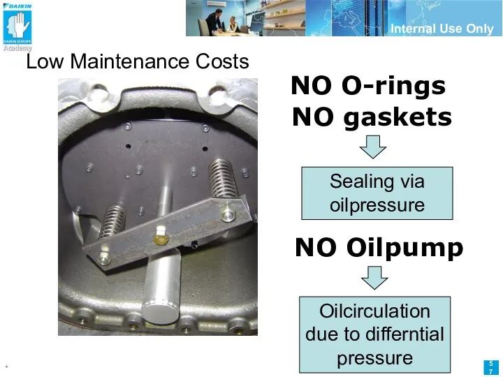
Low Maintenance Costs
… and two sliding parts
NO O-rings
NO gaskets
NO Oilpump
Low Maintenance Costs
… and two sliding parts
NO O-rings
NO gaskets
NO Oilpump
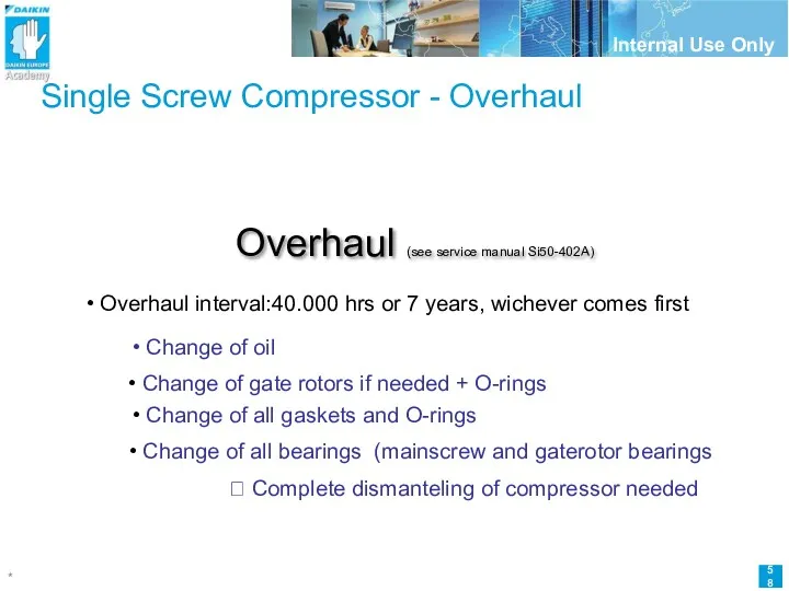
Single Screw Compressor - Overhaul
Overhaul (see service manual Si50-402A)
Overhaul interval:40.000
Single Screw Compressor - Overhaul
Overhaul (see service manual Si50-402A)
Overhaul interval:40.000
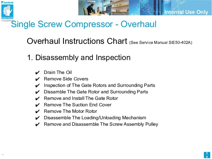
Single Screw Compressor - Overhaul
Overhaul Instructions Chart (See Service Manual SiE50-402A)
1.
Single Screw Compressor - Overhaul
Overhaul Instructions Chart (See Service Manual SiE50-402A)
1.
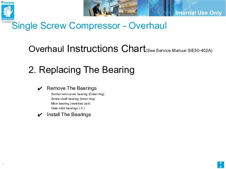
Single Screw Compressor - Overhaul
Overhaul Instructions Chart(See Service Manual SiE50-402A)
2. Replacing
Single Screw Compressor - Overhaul
Overhaul Instructions Chart(See Service Manual SiE50-402A)
2. Replacing
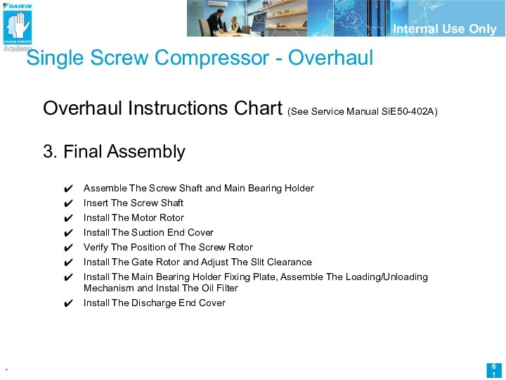
Single Screw Compressor - Overhaul
Overhaul Instructions Chart (See Service Manual SiE50-402A)
3.
Single Screw Compressor - Overhaul
Overhaul Instructions Chart (See Service Manual SiE50-402A)
3.
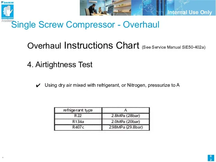
Single Screw Compressor - Overhaul
Overhaul Instructions Chart (See Service Manual SiE50-402a)
4.
Single Screw Compressor - Overhaul
Overhaul Instructions Chart (See Service Manual SiE50-402a)
4.
Single Screw Compressor - Overhaul
Overhaul Instructions Chart (See Service Manual SiE50-402a)
5.
Single Screw Compressor - Overhaul
Overhaul Instructions Chart (See Service Manual SiE50-402a)
5.
Single Screw Compressor - Overhaul
Overhaul Instructions Chart (See Service Manual SiE50-402a)
6.
Single Screw Compressor - Overhaul
Overhaul Instructions Chart (See Service Manual SiE50-402a)
6.
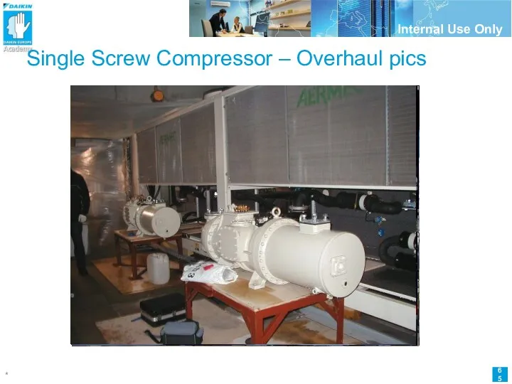
Single Screw Compressor – Overhaul pics
Single Screw Compressor – Overhaul pics
 Биполярные транзисторы
 Групповое занятие по коррекции устной и письменной речи у младших школьников.
 Кем я вижу себя через 7 лет. Ващев Евгений
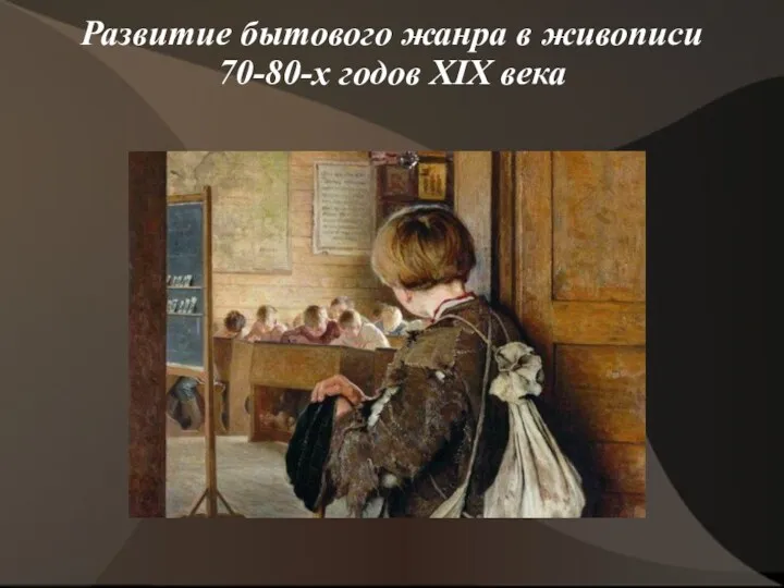 Презентация 11. Бытовой жанр в живописи 70-80-х годов
 Договорные отношения в туристической деятельности. Тема 4
 Самоуправление- важнейший компонент воспитательной системы школы
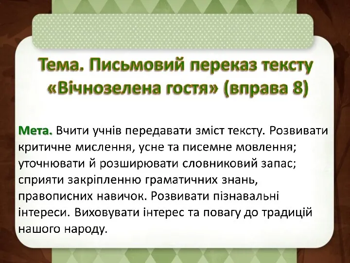 Розвиток мовлення 4 клас ІІ семестр
 Основные производственные процессы в тепловодном карповом прудовом хозяйстве
 Walk, crawl, stagger
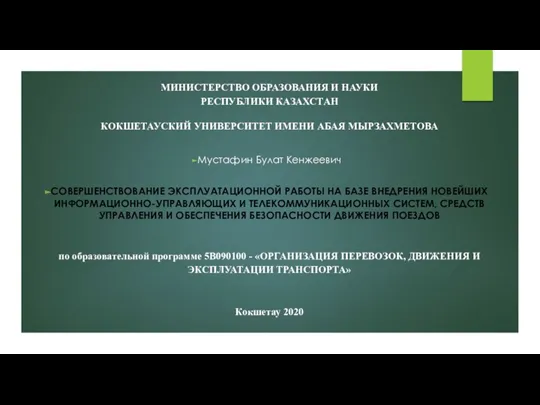 Современные информационно-управляющие системы в управлении движением на железнодорожном транспорте
 Природоведение. Урок знакомства.
 Емдік тамақтандыру. Анемия. Қызба. Оттегі терапия
 Специфика исследований в бизнесе и менеджменте
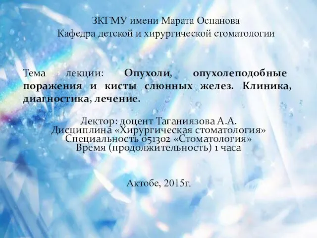 Опухоли, опухолеподобные поражения и кисты слюнных желез. Клиника, диагностика, лечение. (Лекция 7)
 Резные кружева. Русская домовая резьба
 Красный основной соус и его производные
 Поздравление мамам
 Pour rire sans reflechir
 Канальное кодирование. Основы помехоустойчивого кодирования
 Склейка Ландыши
 Физминутка для глаз Звездочет
 Использование игровых методов при принятии решений в условиях риска и неопределенности понятие об игровых методах. Тема 8
 Вопросы репродуктивного здоровья, современные методы обследования и лечения бесплодия
 Универсальные семейные ценности
 Интерактивная игра-викторина по русским народным сказкам для детей старшего дошкольного возраста с ОИН
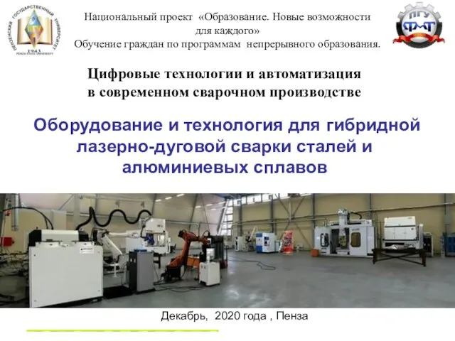 Оборудование и технология для гибридной лазерно-дуговой сварки сталей и алюминиевых сплавов
 Готовимся к ЕГЭ по биологии. Презентация – практикум по подготовке к успешному выполнению задания С5
 Псков. Мастеровой. Гости праздника