- Sky L1,L2 service manual

Содержание
- 2. Agenda Product ………………………p3 Disassembly guide ……… p4-p14 L1&L2 Repairing guide……p15-p24
- 3. Product Model: Platform: MTK6575 LCD: 4.0WVGA 480*800 16.7M TFT Capacitor TP Sup: Dual SIM WCDMA :
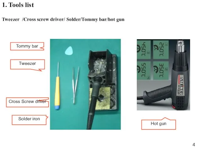
- 4. Hot gun 1. Tools list Tweezer /Cross screw driver/ Solder/Tommy bar/hot gun
- 5. 2. Battery cover disassembly Guide: Disassemble battery cover as below picture; Battery cover
- 6. 3. Back cover disassembly Guide: 1)Unscrew 4 screws in back cover as picture.
- 7. 3. Back cover disassembly Guide: 2)Disassemble back cover with tool as picture; Speaker Vibrator Back cover
- 8. 4.MB&Front cover disassembly Guide: 1)Disconnect LCD connector & TP connector; 9 USB Front Camera CON. LCD
- 9. 4.MB&Front cover disassembly 2)Disconnect one connector as below picture;
- 10. 3)Disassemble MB, then get it out; 4.MB&Front cover disassembly Receiver PCBA Main CAM TP Sub CAM
- 11. 4.MB&Front cover disassembly 4) Disconnect LCD connector ,and Separate LCD from PCBA LCD connector LCD LCD
- 12. Use tweezer to disassemble CAM; 5.CAM disassembly
- 13. 1、Hot air gun degree set as 120℃ 2、Use hot air to heat TP for 2~3 minute.
- 14. 2)Separate TP and front cover as below picture. Note:When you replace new TP, please clean the
- 15. L1&L2 Repairing Guide
- 16. 1. LCD display problem a. Upgrade SW. b. Check if LCD or LCD connector broken, if
- 17. 2. CAM problem a. Check if the CAM connector is loose; b. Replace with a good
- 18. 3. TP problem a. Upgrade SW . b. Check if TP connector is loose; c. Replace
- 19. 4.Rington problem a. Check spring of speaker if it is twisted; b. Check the resister value
- 20. 5.Receiver problem a. Check spring of receiver; b. Check the resister value of receiver; c. Check
- 21. 6.MIC problem a. Check MIC if there is poor soldering; b. Replace a new MIC; c.
- 22. 7. No vibration or earphone problem a. Check spring of vibrator ,check earphone jack if there
- 23. 8. Dead a. Check the voltage of battery if in range 3.8V to 4.2V, then check
- 24. 9.Can not detect SIM card or T card a. Check the socket if there is poor
- 26. Скачать презентацию
Agenda
Product ………………………p3
Disassembly guide ……… p4-p14
L1&L2 Repairing guide……p15-p24
Agenda
Product ………………………p3
Disassembly guide ……… p4-p14
L1&L2 Repairing guide……p15-p24
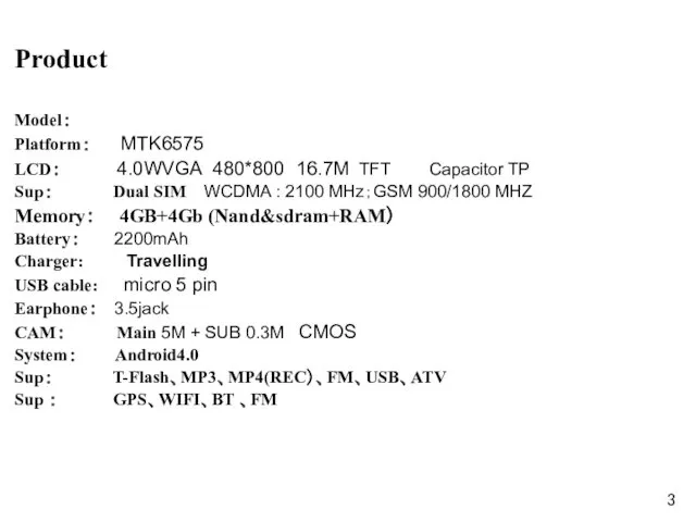
Product
Model:
Platform: MTK6575
LCD: 4.0WVGA 480*800 16.7M TFT Capacitor TP
Sup: Dual SIM WCDMA
Product
Model:
Platform: MTK6575
LCD: 4.0WVGA 480*800 16.7M TFT Capacitor TP
Sup: Dual SIM WCDMA
Hot gun
1. Tools list
Tweezer /Cross screw driver/ Solder/Tommy bar/hot gun
Hot gun
1. Tools list
Tweezer /Cross screw driver/ Solder/Tommy bar/hot gun
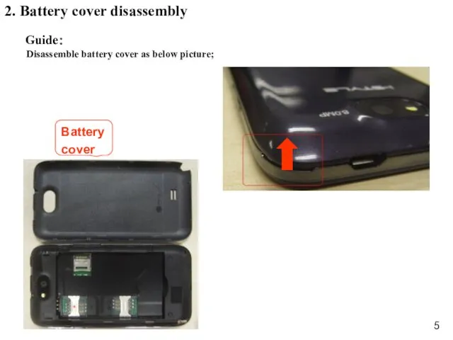
2. Battery cover disassembly
Guide:
Disassemble battery cover as below picture;
Battery
cover
2. Battery cover disassembly
Guide:
Disassemble battery cover as below picture;
Battery
cover
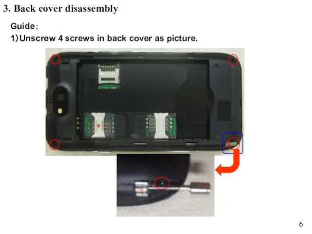
3. Back cover disassembly
Guide:
1)Unscrew 4 screws in back cover as picture.
3. Back cover disassembly
Guide:
1)Unscrew 4 screws in back cover as picture.
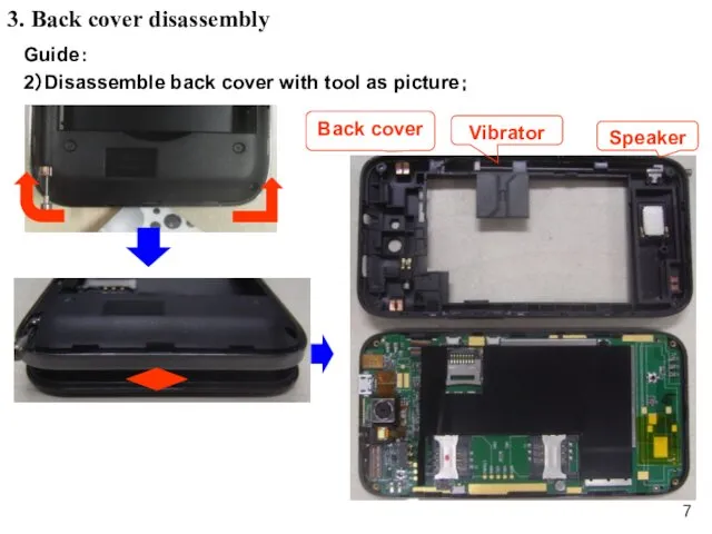
3. Back cover disassembly
Guide:
2)Disassemble back cover with tool as picture;
Speaker
Vibrator
Back cover
3. Back cover disassembly
Guide:
2)Disassemble back cover with tool as picture;
Speaker
Vibrator
Back cover
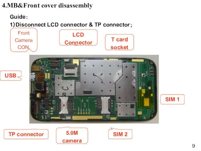
4.MB&Front cover disassembly
Guide:
1)Disconnect LCD connector & TP connector;
9
USB
Front
Camera
CON.
LCD
Connector
T card
socket
TP connector
5.0M
camera
SIM 2
SIM
4.MB&Front cover disassembly
Guide:
1)Disconnect LCD connector & TP connector;
9
USB
Front
Camera
CON.
LCD
Connector
T card
socket
TP connector
5.0M
camera
SIM 2
SIM
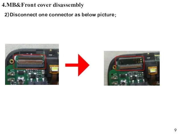
4.MB&Front cover disassembly
2)Disconnect one connector as below picture;
4.MB&Front cover disassembly
2)Disconnect one connector as below picture;
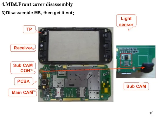
3)Disassemble MB, then get it out;
4.MB&Front cover disassembly
Receiver
PCBA
Main CAM
TP
Sub CAM
3)Disassemble MB, then get it out;
4.MB&Front cover disassembly
Receiver
PCBA
Main CAM
TP
Sub CAM
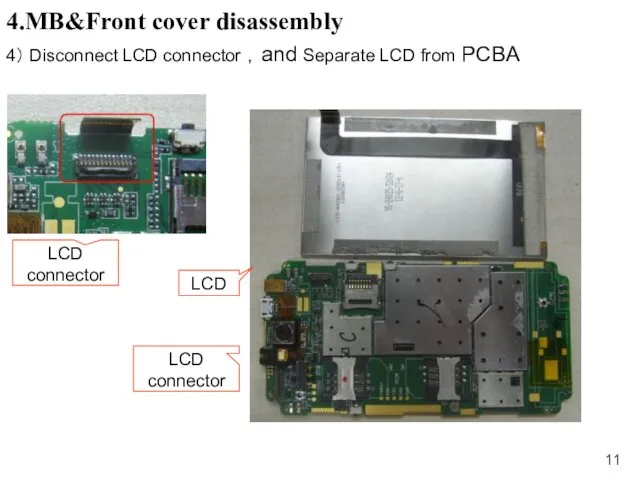
4.MB&Front cover disassembly
4) Disconnect LCD connector ,and Separate LCD from PCBA
LCD
4.MB&Front cover disassembly
4) Disconnect LCD connector ,and Separate LCD from PCBA
LCD
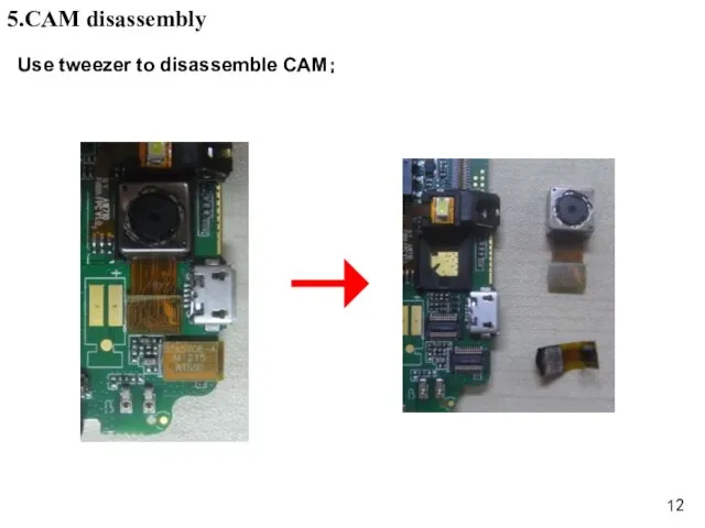
Use tweezer to disassemble CAM;
5.CAM disassembly
Use tweezer to disassemble CAM;
5.CAM disassembly
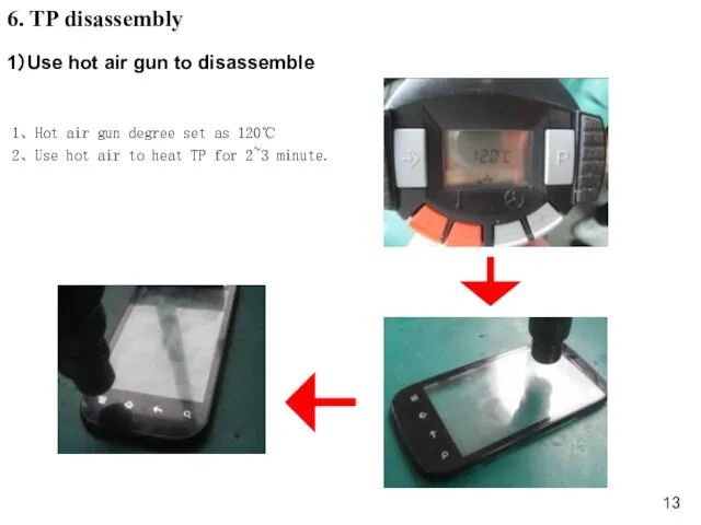
1、Hot air gun degree set as 120℃
2、Use hot air to heat
1、Hot air gun degree set as 120℃
2、Use hot air to heat
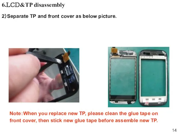
2)Separate TP and front cover as below picture.
Note:When you replace new
2)Separate TP and front cover as below picture.
Note:When you replace new
L1&L2 Repairing Guide
L1&L2 Repairing Guide
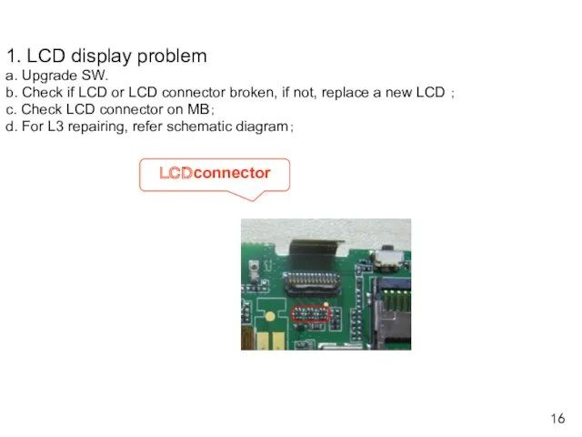
1. LCD display problem
a. Upgrade SW.
b. Check if LCD or LCD
a. Upgrade SW.
b. Check if LCD or LCD
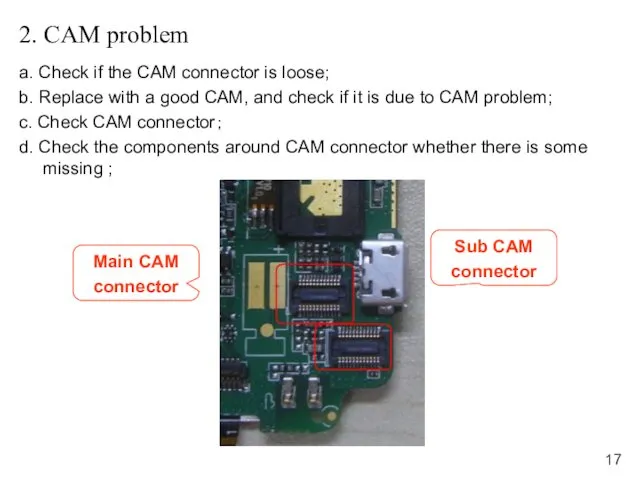
2. CAM problem
a. Check if the CAM connector is loose;
b. Replace
2. CAM problem
a. Check if the CAM connector is loose;
b. Replace
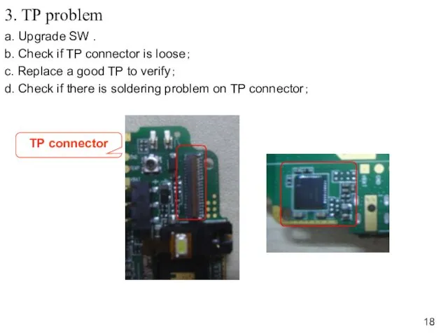
3. TP problem
a. Upgrade SW .
b. Check if TP connector is
3. TP problem
a. Upgrade SW .
b. Check if TP connector is
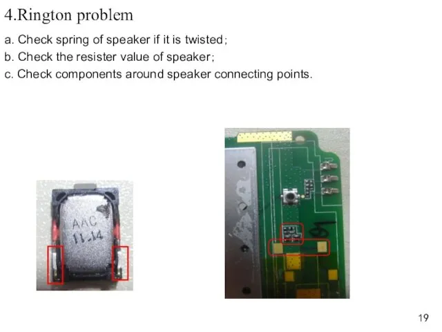
4.Rington problem
a. Check spring of speaker if it is twisted;
b. Check
4.Rington problem
a. Check spring of speaker if it is twisted;
b. Check
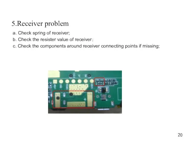
5.Receiver problem
a. Check spring of receiver;
b. Check the resister value of
5.Receiver problem
a. Check spring of receiver;
b. Check the resister value of
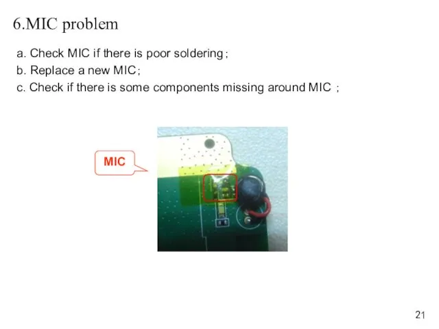
6.MIC problem
a. Check MIC if there is poor soldering;
b. Replace a
6.MIC problem
a. Check MIC if there is poor soldering;
b. Replace a
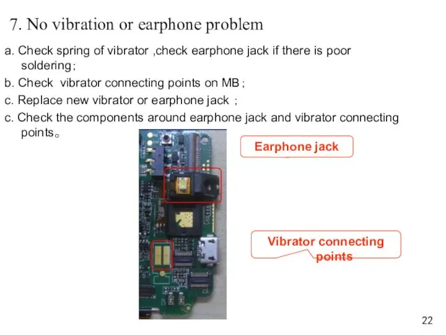
7. No vibration or earphone problem
a. Check spring of vibrator ,check
7. No vibration or earphone problem
a. Check spring of vibrator ,check
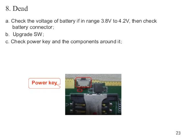
8. Dead
a. Check the voltage of battery if in range 3.8V
8. Dead
a. Check the voltage of battery if in range 3.8V
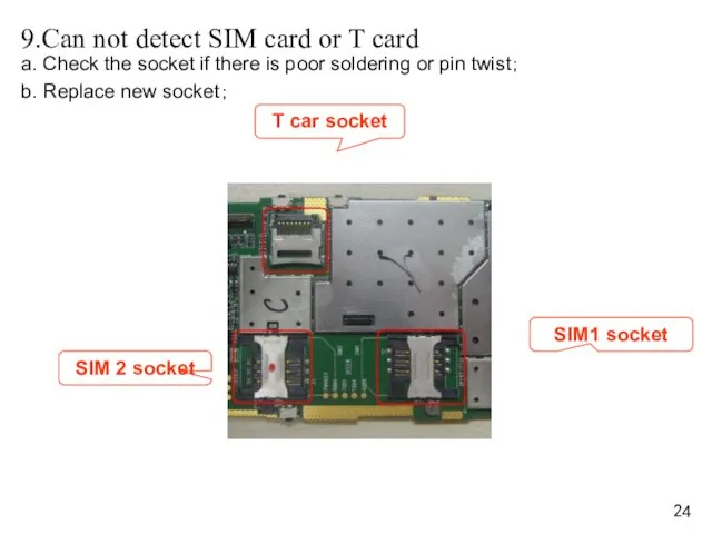
9.Can not detect SIM card or T card
a. Check the socket
9.Can not detect SIM card or T card
a. Check the socket
 Особенности организации производства: в нашей стране и за рубежом
 Социально-экономическое развитие страны на рубеже XIX-XX века
 Наша Родина
 Создание контента в Instagram
 Урок-презентация
 На что тратят деньги британские подростки
 Бронхиты у детей. Инфекции верхних дыхательных путей
 Презентация: Дикие животные
 Япония. Японская письменность
 Ковальська справа
 Экономика потребителя
 В Александрии Египетской. 5 класс
 Дизайн и архитектура сада
 Производные тригонометрических функций
 Красота в искусстве и жизни
 Схемотехнические основы компьютерной техники
 Едет, плывет, летит. Для детей 4 - 5 лет
 Frontol Discount Unit
 Озеро Байкал - жемчужина Сибири
 Домашние млекопитающие. Отрасли животноводства
 Золотая свадьба. Фото
 Тысячи фильмов и сериалов по цене одного. Федеральная акция КИНОМАНИЯ
 Презентация Культура речи и средства эффективного общения
 Правовые основы брака и семьи
 Ребенок и его права
 Тематика выпускных квалификационных работ
 Проект на тему Почему нам интересно ходить в библиотеку
 Папа с мамой, помогите смастерить кормушку!