- Switching systems

Содержание
- 2. The concept of pulse code modulation (PCM) Conversion of the primary continuous analog signal into a
- 3. Kotelnikov Theorem According to the Nyquist theorem, any analog (continuous), the signal can be sampled, and
- 4. The quantization of signal The sampled amplitude pulses correspond to the instantaneous values of the signal.
- 5. Converting an analog signal to PCM signal
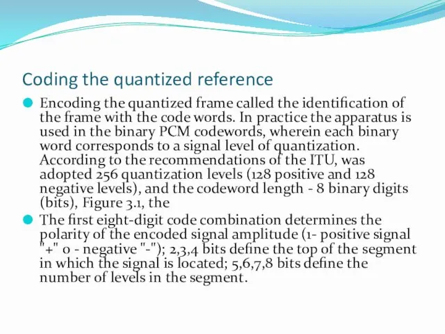
- 6. Coding the quantized reference Encoding the quantized frame called the identification of the frame with the
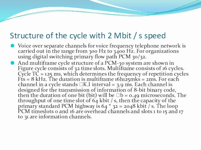
- 7. Structure of the cycle with 2 Mbit / s speed Voice over separate channels for voice
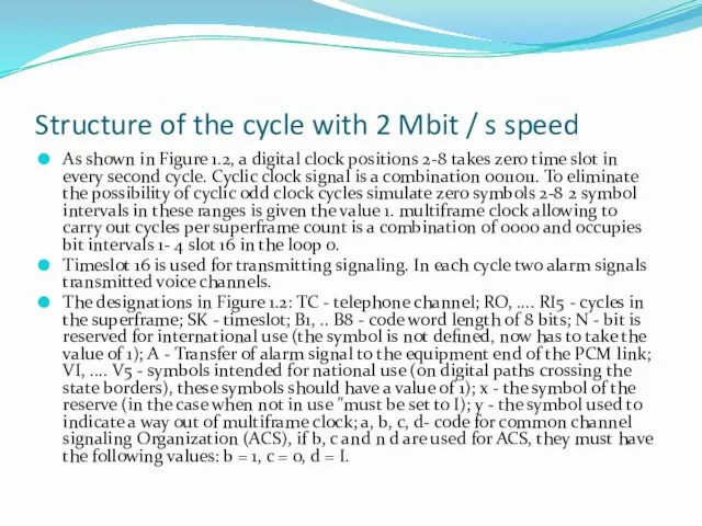
- 8. Structure of the cycle with 2 Mbit / s speed As shown in Figure 1.2, a
- 9. The structure of the cycle and multiframe of PCM-30 equipment
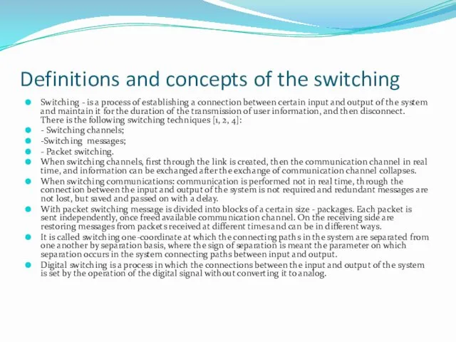
- 10. Definitions and concepts of the switching Switching - is a process of establishing a connection between
- 11. The principle of transformation of the time coordinate of the digital signal (the principle of time
- 12. Illustration of time switching principle
- 13. Vector representation of time switching
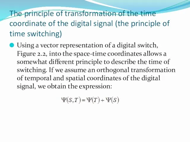
- 14. The principle of transformation of the time coordinate of the digital signal (the principle of time
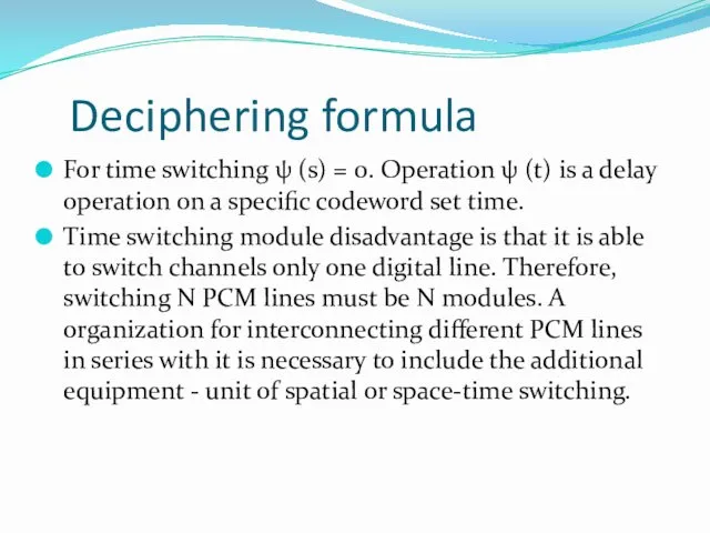
- 15. Deciphering formula For time switching ψ (s) = 0. Operation ψ (t) is a delay operation
- 16. The principle of conversion of the spatial coordinates of the digital signal (the principle of spatial
- 17. Illustration of the principle of spatial switching
- 18. Vector representation of spatial switching
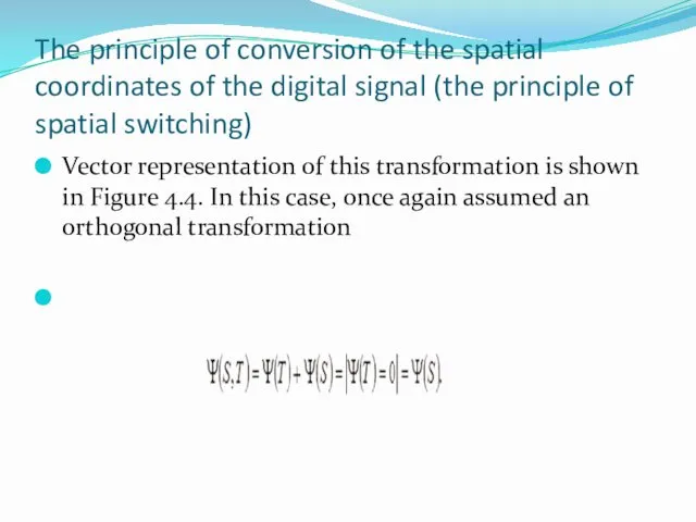
- 19. The principle of conversion of the spatial coordinates of the digital signal (the principle of spatial
- 20. Deciphering formula CP Digital, built on the space switching modules are widely used in the early
- 21. The principle of the space-time switching Unit or module implements a space-time coordinate transformation of a
- 22. Illustration of the principle of space-time switching
- 23. Vector representation of space-time switching
- 24. Digital switching fields 1, 2, 3, 4, 5 th grade
- 25. Principles of the construction of DSF Switching the system reflects the principles of the internal construction
- 26. Features of construction of multi-digital manual 1. Digital manuals are built using a certain number of
- 27. Five classes Taking into account the symmetry and the modular construction of the entire set of
- 28. CSF of the First Class Initially, the basis for these types of units CSF spatial switching
- 29. The basic structure of a first-class CSF
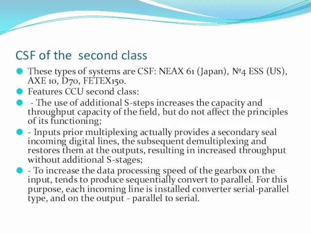
- 30. CSF of the second class These types of systems are CSF: NEAX 61 (Japan), №4 ESS
- 31. The basic structure of the second class CSF
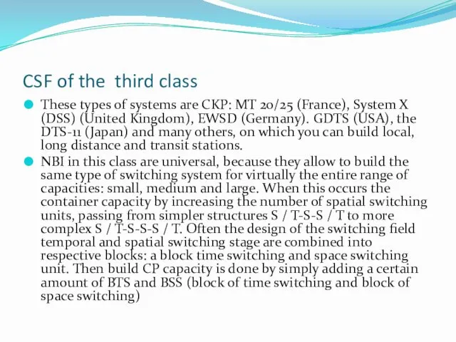
- 32. CSF of the third class These types of systems are CKP: MT 20/25 (France), System X
- 33. The basic structure of the third class CSF
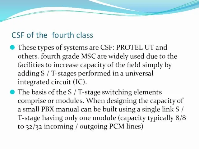
- 34. CSF of the fourth class These types of systems are CSF: PROTEL UT and others. fourth
- 35. The basic structure of the fourth class CSF
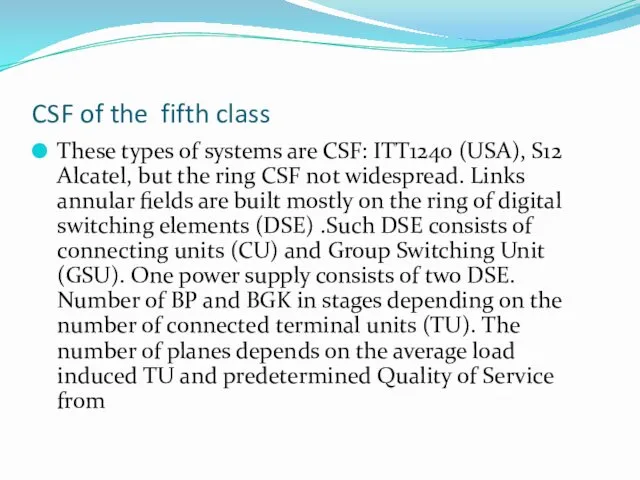
- 36. CSF of the fifth class These types of systems are CSF: ITT1240 (USA), S12 Alcatel, but
- 37. The basic structure of the fifth class CSF
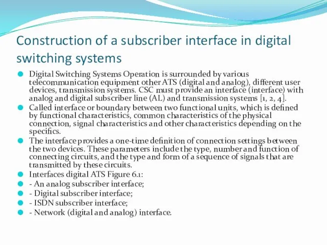
- 38. Construction of a subscriber interface in digital switching systems Digital Switching Systems Operation is surrounded by
- 39. Interfaces of digital switching systems
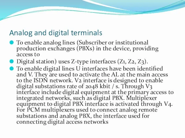
- 40. Analog and digital terminals To enable analog lines (Subscriber or institutional production exchanges (PBXs) in the
- 41. Analog subscriber interface and the problem BORSCHT With the creation and implementation of digital exchanges have
- 42. Description of BORSCHT function
- 43. Description of BORSCHT function
- 44. Addressing of organizations analog subscriber interface implementation - Approval by the form of the transmitted voice
- 45. Network interfaces of digital ATS (STS)
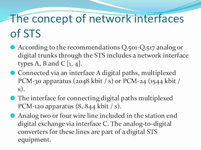
- 46. The concept of network interfaces of STS According to the recommendations Q.501-Q.517 analog or digital trunks
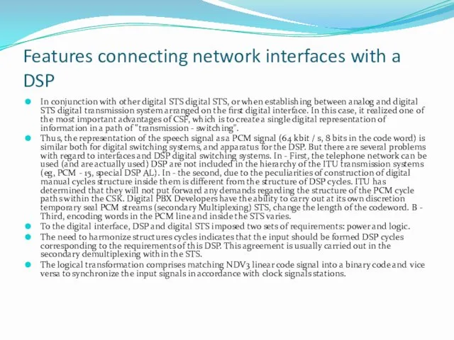
- 47. Features connecting network interfaces with a DSP In conjunction with other digital STS digital STS, or
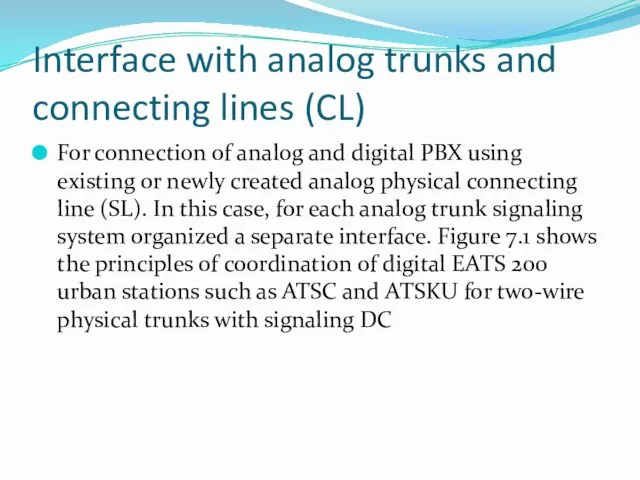
- 48. Interface with analog trunks and connecting lines (CL) For connection of analog and digital PBX using
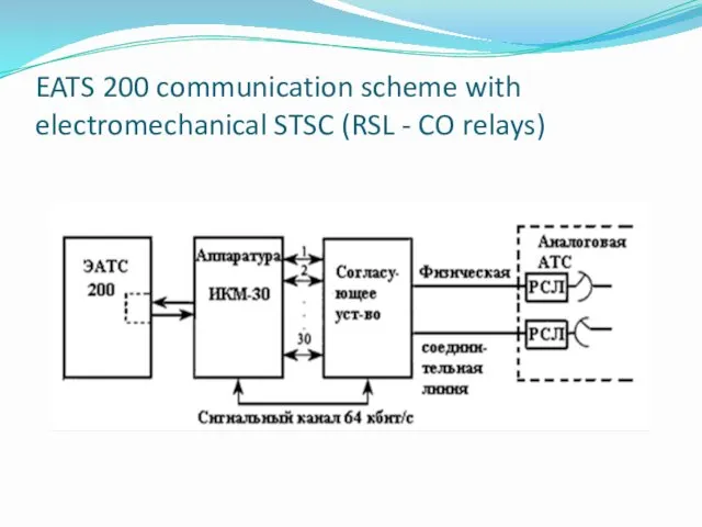
- 49. EATS 200 communication scheme with electromechanical STSC (RSL - CO relays)
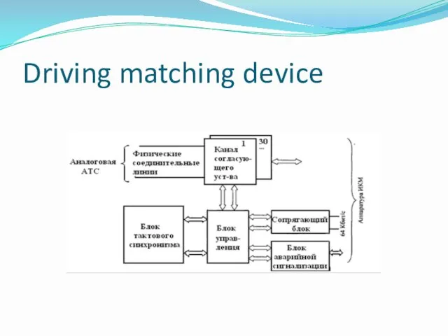
- 50. Driving matching device
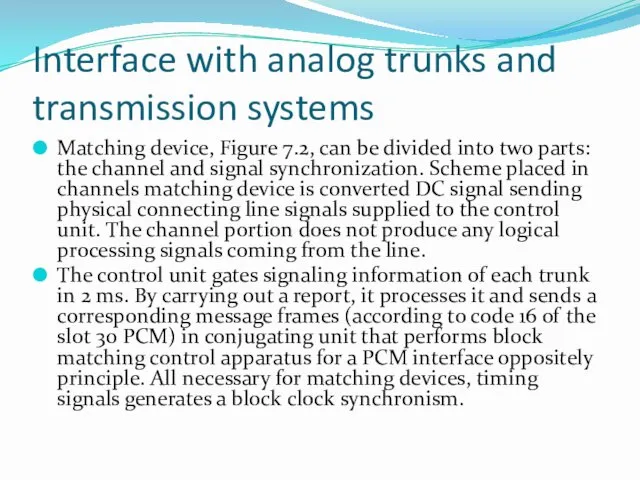
- 51. Interface with analog trunks and transmission systems Matching device, Figure 7.2, can be divided into two
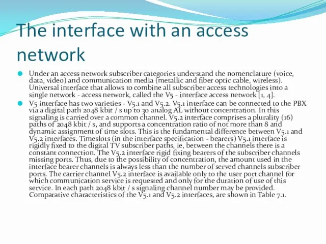
- 52. The interface with an access network Under an access network subscriber categories understand the nomenclature (voice,
- 53. Table 7.1. - Comparative characteristics of V5.1 and V5.2 interfaces
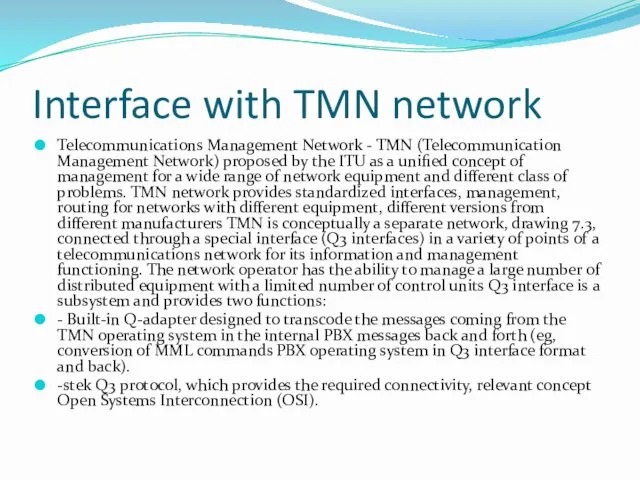
- 54. Interface with TMN network Telecommunications Management Network - TMN (Telecommunication Management Network) proposed by the ITU
- 55. Figure 7.3 - The interaction between the telecommunications network and TNM
- 57. Скачать презентацию
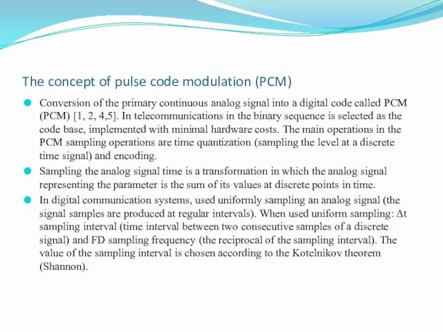
The concept of pulse code modulation (PCM)
Conversion of the primary continuous
The concept of pulse code modulation (PCM)
Conversion of the primary continuous
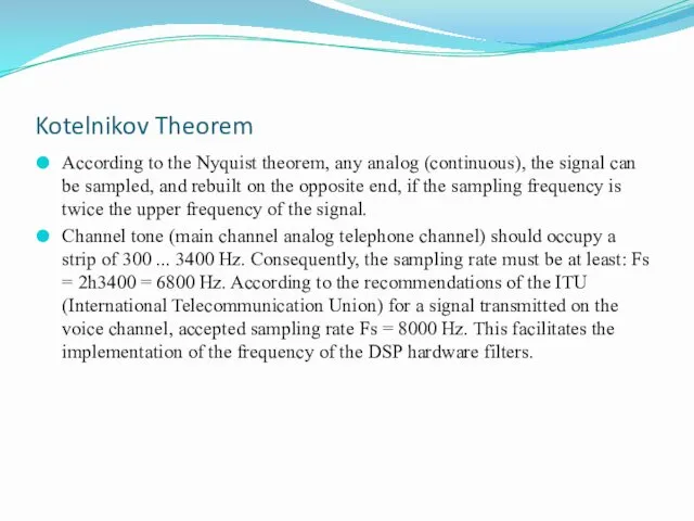
Kotelnikov Theorem
According to the Nyquist theorem, any analog (continuous), the signal
Kotelnikov Theorem
According to the Nyquist theorem, any analog (continuous), the signal
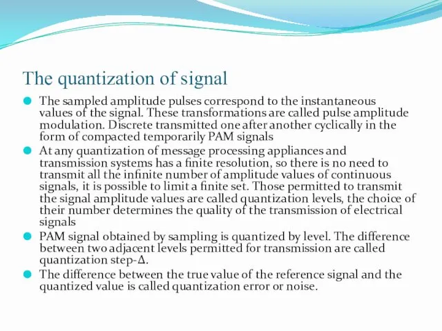
The quantization of signal
The sampled amplitude pulses correspond to the instantaneous
The quantization of signal
The sampled amplitude pulses correspond to the instantaneous
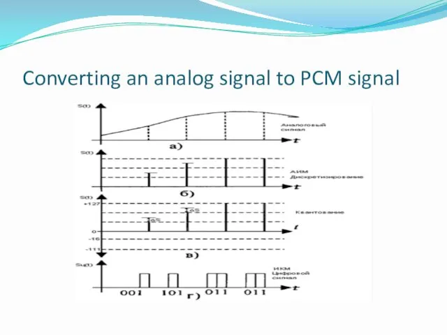
Converting an analog signal to PCM signal
Converting an analog signal to PCM signal
Coding the quantized reference
Encoding the quantized frame called the identification of
Coding the quantized reference
Encoding the quantized frame called the identification of
Structure of the cycle with 2 Mbit / s speed
Voice over
Structure of the cycle with 2 Mbit / s speed
Voice over
Structure of the cycle with 2 Mbit / s speed
As shown
Structure of the cycle with 2 Mbit / s speed
As shown
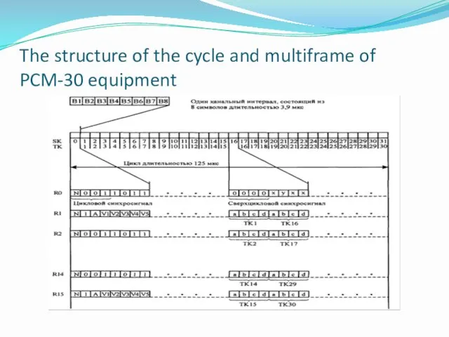
The structure of the cycle and multiframe of PCM-30 equipment
The structure of the cycle and multiframe of PCM-30 equipment
Definitions and concepts of the switching
Switching - is a process of
Definitions and concepts of the switching
Switching - is a process of
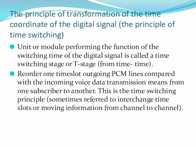
The principle of transformation of the time coordinate of the digital
The principle of transformation of the time coordinate of the digital
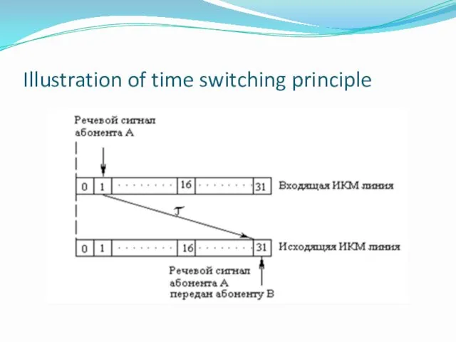
Illustration of time switching principle
Illustration of time switching principle
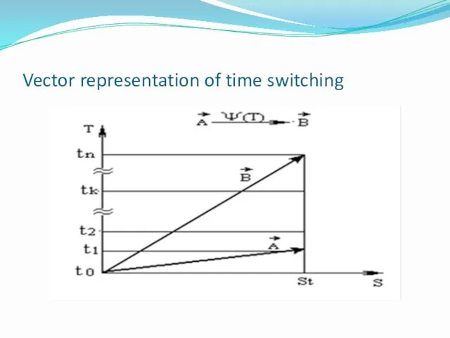
Vector representation of time switching
Vector representation of time switching
The principle of transformation of the time coordinate of the digital
The principle of transformation of the time coordinate of the digital
Deciphering formula
For time switching ψ (s) = 0. Operation ψ (t)
Deciphering formula
For time switching ψ (s) = 0. Operation ψ (t)
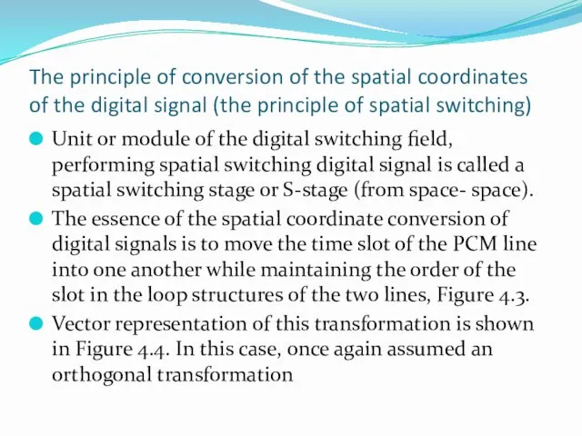
The principle of conversion of the spatial coordinates of the digital
The principle of conversion of the spatial coordinates of the digital
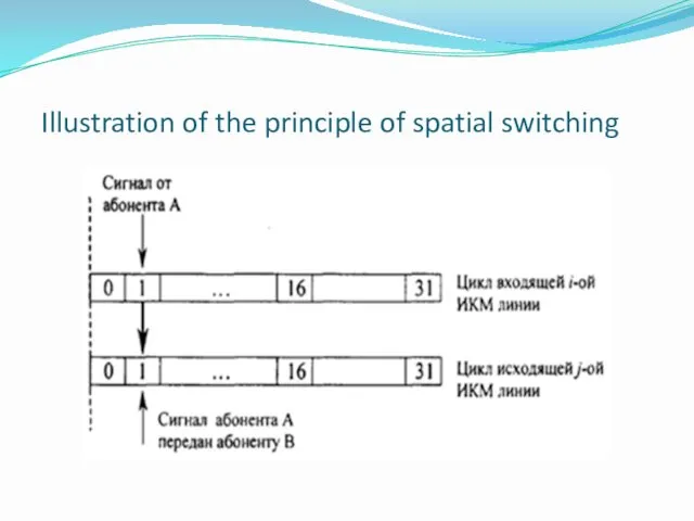
Illustration of the principle of spatial switching
Illustration of the principle of spatial switching
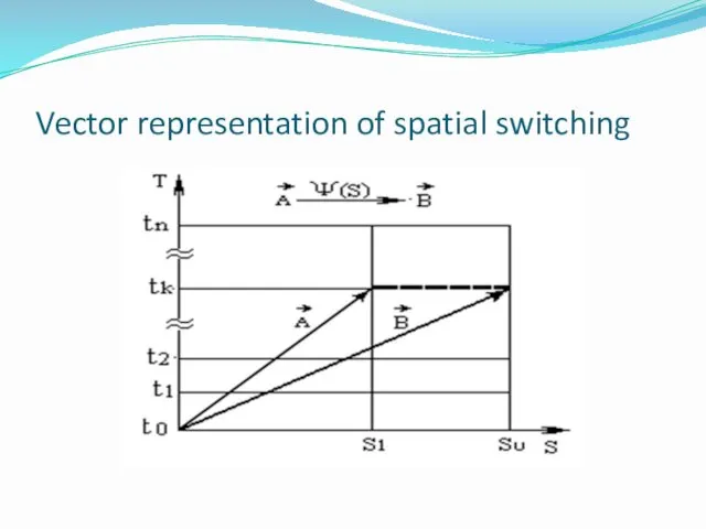
Vector representation of spatial switching
Vector representation of spatial switching
The principle of conversion of the spatial coordinates of the digital
The principle of conversion of the spatial coordinates of the digital
Deciphering formula
CP Digital, built on the space switching modules are widely
Deciphering formula
CP Digital, built on the space switching modules are widely
The principle of the space-time switching
Unit or module implements a space-time
The principle of the space-time switching
Unit or module implements a space-time
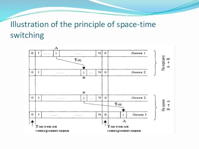
Illustration of the principle of space-time switching
Illustration of the principle of space-time switching
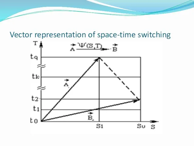
Vector representation of space-time switching
Vector representation of space-time switching
Digital switching fields 1, 2, 3, 4, 5 th grade
Digital switching fields 1, 2, 3, 4, 5 th grade
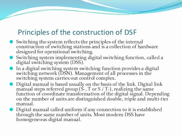
Principles of the construction of DSF
Switching the system reflects the principles
Principles of the construction of DSF
Switching the system reflects the principles
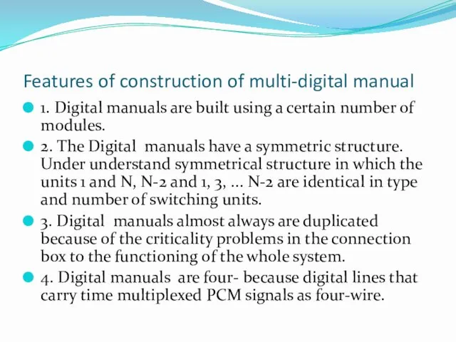
Features of construction of multi-digital manual
1. Digital manuals are built using
Features of construction of multi-digital manual
1. Digital manuals are built using
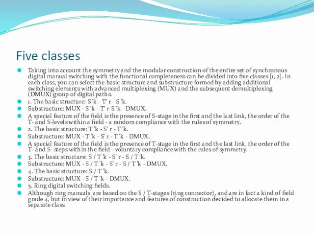
Five classes
Taking into account the symmetry and the modular construction of
Five classes
Taking into account the symmetry and the modular construction of
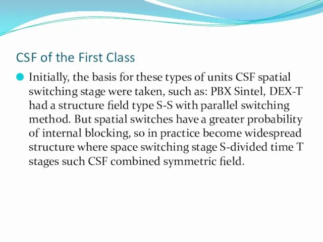
CSF of the First Class
Initially, the basis for these types of
CSF of the First Class
Initially, the basis for these types of
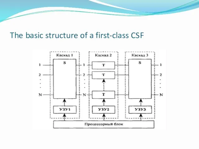
The basic structure of a first-class CSF
The basic structure of a first-class CSF
CSF of the second class
These types of systems are CSF: NEAX
CSF of the second class
These types of systems are CSF: NEAX
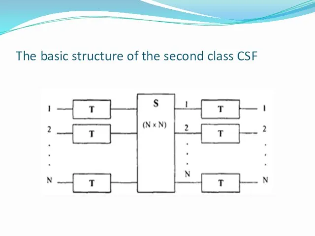
The basic structure of the second class CSF
The basic structure of the second class CSF
CSF of the third class
These types of systems are CKP: MT
CSF of the third class
These types of systems are CKP: MT
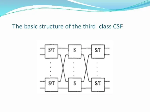
The basic structure of the third class CSF
The basic structure of the third class CSF
CSF of the fourth class
These types of systems are CSF: PROTEL
CSF of the fourth class
These types of systems are CSF: PROTEL
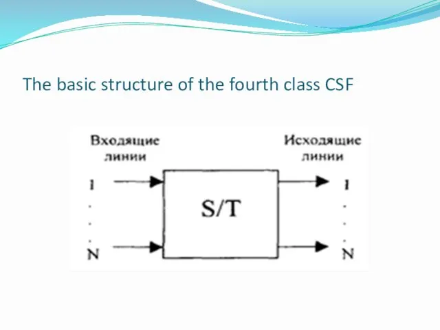
The basic structure of the fourth class CSF
The basic structure of the fourth class CSF
CSF of the fifth class
These types of systems are CSF: ITT1240
CSF of the fifth class
These types of systems are CSF: ITT1240
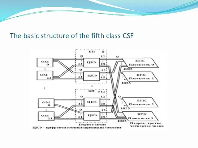
The basic structure of the fifth class CSF
The basic structure of the fifth class CSF
Construction of a subscriber interface in digital switching systems
Digital Switching Systems
Construction of a subscriber interface in digital switching systems
Digital Switching Systems
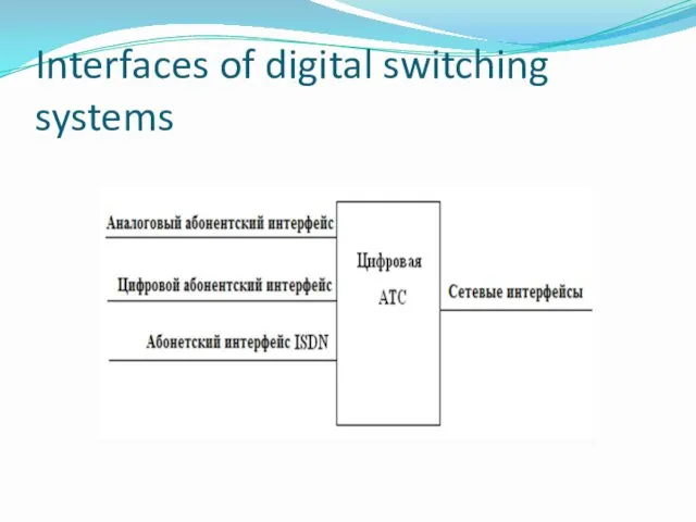
Interfaces of digital switching systems
Interfaces of digital switching systems
Analog and digital terminals
To enable analog lines (Subscriber or institutional production
Analog and digital terminals
To enable analog lines (Subscriber or institutional production
Analog subscriber interface and the problem BORSCHT
With the creation and implementation
Analog subscriber interface and the problem BORSCHT
With the creation and implementation
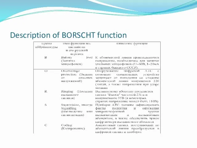
Description of BORSCHT function
Description of BORSCHT function
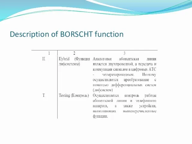
Description of BORSCHT function
Description of BORSCHT function
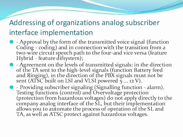
Addressing of organizations analog subscriber interface implementation
- Approval by the form
Addressing of organizations analog subscriber interface implementation
- Approval by the form
Network interfaces of digital ATS (STS)
Network interfaces of digital ATS (STS)
The concept of network interfaces of STS
According to the recommendations Q.501-Q.517
The concept of network interfaces of STS
According to the recommendations Q.501-Q.517
Features connecting network interfaces with a DSP
In conjunction with other digital
Features connecting network interfaces with a DSP
In conjunction with other digital
Interface with analog trunks and connecting lines (CL)
For connection of analog
Interface with analog trunks and connecting lines (CL)
For connection of analog
EATS 200 communication scheme with electromechanical STSC (RSL - CO relays)
EATS 200 communication scheme with electromechanical STSC (RSL - CO relays)
Driving matching device
Driving matching device
Interface with analog trunks and transmission systems
Matching device, Figure 7.2, can
Interface with analog trunks and transmission systems
Matching device, Figure 7.2, can
The interface with an access network
Under an access network subscriber categories
The interface with an access network
Under an access network subscriber categories
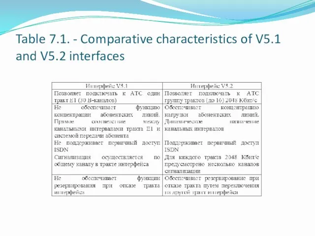
Table 7.1. - Comparative characteristics of V5.1 and V5.2 interfaces
Table 7.1. - Comparative characteristics of V5.1 and V5.2 interfaces
Interface with TMN network
Telecommunications Management Network - TMN (Telecommunication Management Network)
Interface with TMN network
Telecommunications Management Network - TMN (Telecommunication Management Network)
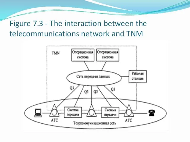
Figure 7.3 - The interaction between the telecommunications network and TNM
Figure 7.3 - The interaction between the telecommunications network and TNM
 МАРК-SQL электронная программа
 Результаты педагогической деятельности
 Презентация и буклет к Международному дню семьи Вместе не страшны и тучи!
 Линейные неравенства с одним неизвестным
 Сатирикон - русский еженедельный сатирический журнал. История журнала. Имена
 Организация обучения в аспирантуре НИУ БелГУ
 Разработка проекта наладки РТК на базе станка с ЧПУ на обработку детали Шестерня VIII оси 1к62-02-119
 Психологическая и речевая готовностьдетейк школе
 Орден Улыбок
 Знаменитые люди поселка Вырица. Иван Антонович Ефремов
 Сравнительная характеристика религиозного состава населения Земли и России
 Устройство компьютера
 Возникновение ислама
 Сжатое изложение. Приёмы компрессии текста
 Формирование лексико-грамматического строя речи у учащихся на уроках, коррекционных занятий
 Творческий проект Русская народная сказка Заюшкина избушка,с детьми раннего возраста.
 Reserve Kruger Park
 Электрические методы каротажа. Часть 2. Лекция № 3
 Проект по теме Повар
 Кремний и его соединения. Презентация к уроку химии 9 класс
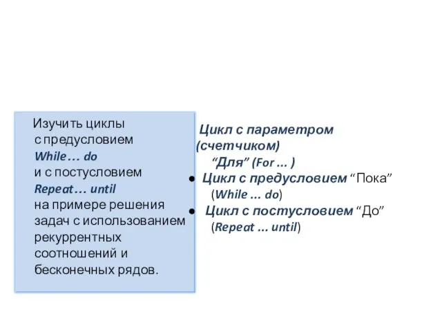 Циклы с предусловием While. Цикл с постусловием Repeat
 Использование метода круговой тренировки для повышения функциональных способностей боксеров
 Географические координаты
 Поняття, ознаки, принципи формування сучасних міжнародних організацій
 Информационные технологии на предприятиях нефтегазовой отрасли
 Реальность и фантазия в творчестве художника
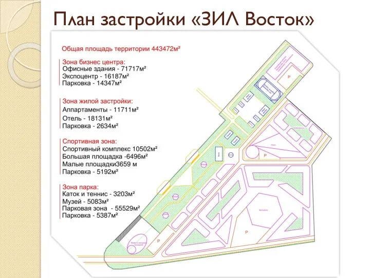 План застройки ЗИЛ Восток
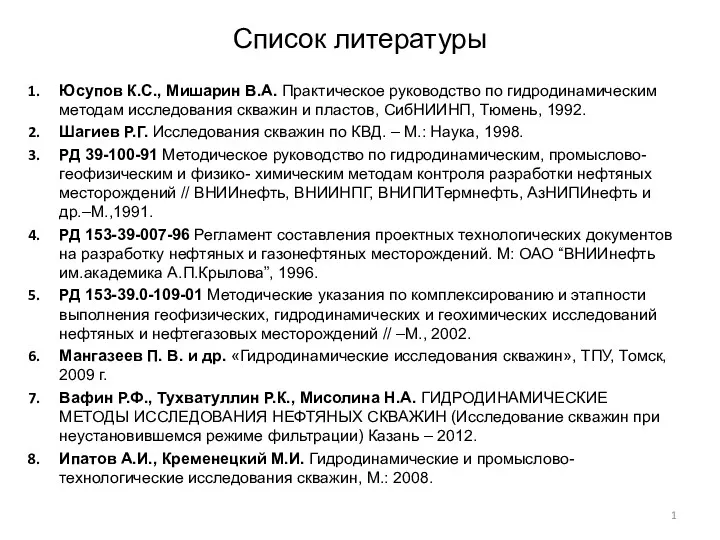 Практическое руководство по гидродинамическим методам исследования скважин и пластов