- Training Book. Samsung Home Theater

Содержание
- 2. List Of Contests 1. General Feature of the HT-TXQ120 2. Description of the SET 3. How
- 3. 1. General Feature
- 4. 2.Description Of the MAIN SET
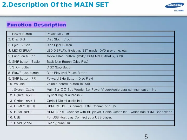
- 5. 2.Description Of the MAIN SET Function Description
- 6. 2.Description Of the Sub Woofer
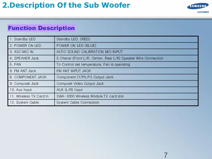
- 7. 2.Description Of the Sub Woofer Function Description
- 8. Accessories
- 9. 3. How to disassemble the MAIN set
- 10. 3.How to disassemble the MAIN set 1. Unfasten 12 screws on side of Back Cover 2.Lift
- 11. 3. How to disassemble the MAIN set Unfasten the Cables (Flat/Wire Cables), Push the hook (4
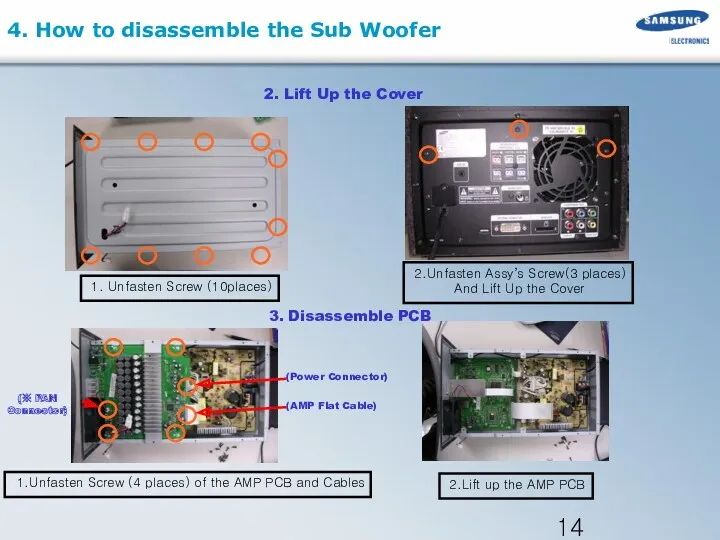
- 12. 4. How to disassemble the Sub Woofer
- 13. 4. How to disassemble the Sub Woofer 1. Unfasten 4 Screws of the bottom. 밑면 1.
- 14. 1. Unfasten Screw (10places) 2. Lift Up the Cover 2.Unfasten Assy’s Screw(3 places) And Lift Up
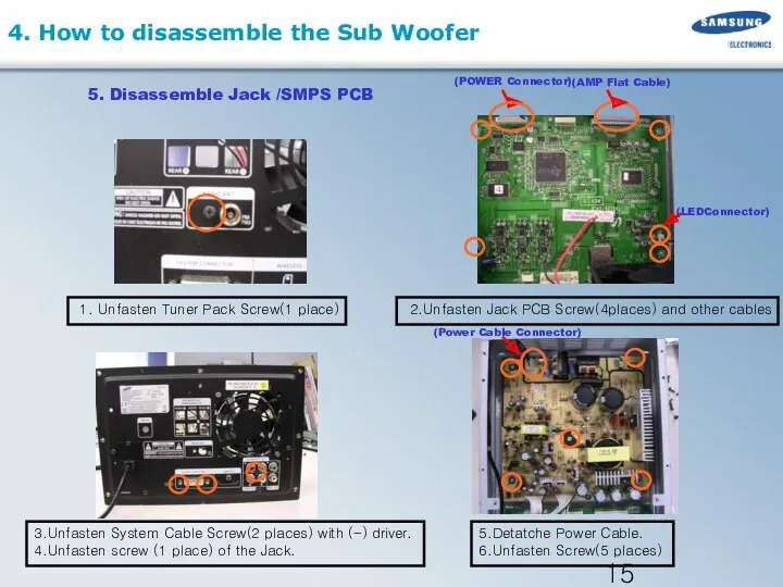
- 15. 1. Unfasten Tuner Pack Screw(1 place) 5. Disassemble Jack /SMPS PCB 2.Unfasten Jack PCB Screw(4places) and
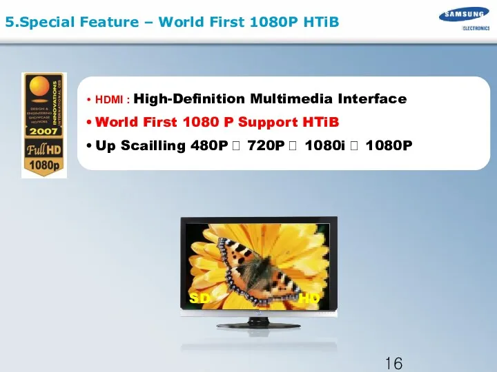
- 16. 5.Special Feature – World First 1080P HTiB SD HD HDMI : High-Definition Multimedia Interface World First
- 17. HDMI (High Definition Multimedia Interface) - Pure Digital for Perfect Vision HDMI OUTPUT - High Definition
- 18. 5. BLOCK DIAGRAM 5.Special Feature – WIRELESS READY Block Diagram
- 19. 7. Wireless ready module 8. Wireless ready port Standby(Time Line) SWA3000 Communication Error DATA/CLK PORT Power
- 20. Micom MPEG 6.MAIN PCB Block OPTICAL/HDMI / USB / ASC JACK WM 8746 MICOM OPTION POWER
- 21. 6.MAIN PCB Connectors UCON3 UDIN2 UDIN1 RFCN4 RFCN3 RFCN1 UCON5 UCON4 UCON6 UCON1
- 22. DSP 6.JACK PCB Block WIRELESS SLOT / VIDEO AUDIO JACK MICOM MICOM UPDATE WM8775 SYSTEM JACK
- 23. 6.JACK PCB Connectors JCON1 JCON4 JCON21 JCON6 JCON7
- 24. 6.Block Diagram (Amp Block) PS9829B
- 25. 6.AMP PCB PWM MODULATOR LOW PASS FILTER POWER STAGE TAS5152 FAN CIRCUIT SPEAKER JACK PCB CONNECTOR
- 26. 6.AMP Modulator (PS9829B) FRONT & REAR “L” SUBWOOFER LR CLOCK MICOM CONTROL REAR & FRONT “R”
- 27. 6.AMP Power Stage TAS5152 2)TAS5152 #3 pin : Protection, Auto Shut Down (open or short )
- 28. 6.SMPS Protection Cases of the SMPS Protection. 1> If there is over current at the AMP
- 29. 6. AMP Pre-Inspection relating to Power Protection If you think, there are problems at the AMP
- 30. 6.Block Diagram in detail (HDMI) SCALER FLI2301 SDRAM W983264DH HDMI Tx SIL9030 13.5MHz ENCODER SAA7128AH Component
- 31. 1) HDMI Transmitter MPEG HDMI Tx SiI9030 HDMI Rx SiI9011 Micom GENESIS FLI2301 Video Encoder SAA7128
- 32. 6.MAIN PCB (HDMI) VIDEO IC FLI2301 Display-Driver IC HDMI TX Sil9030 HDMI-Transmitter IC HDMI RX Sil9011
- 33. 6.Checking out AMP PCB CHECK
- 34. 6.AMP PCB Short Check flow 1)Check parts. (short/IC damage/pattern damage) 2) Check connectors 3) Short test
- 35. 6.SMPS Check Flow 1)Check FUSE & VARISTOR 2)Check the AC Input Cord 3) Check cables 4)
- 36. 7.Deck Assy. AH59-01769A
- 37. 2. Separate Pick-Up Cable from the Holder 1.To Protect PICK-UP, Before detach Flat Cable that point
- 38. 4. Unfasten 4 Screws saparate Traverse-Deck 3. Unfasten 2 Screws lift up Holder-Cable 7.Mecha Disassemble (MECHA-DECK)
- 39. Traverse-Deck Rubber-Deck Holder-Cable 7.Mecha Disassemble (MECHA-DECK)
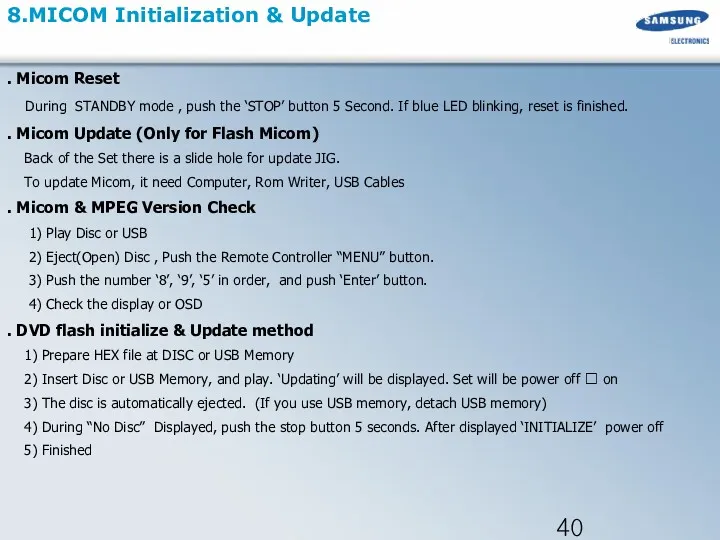
- 40. 8.MICOM Initialization & Update . Micom Reset During STANDBY mode , push the ‘STOP’ button 5
- 41. 9. Troubleshooting 1 . Main
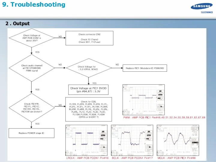
- 42. 9. Troubleshooting 2 . Output
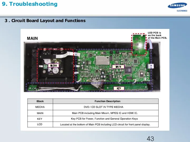
- 43. 9. Troubleshooting 3 . Circuit Board Layout and Functions
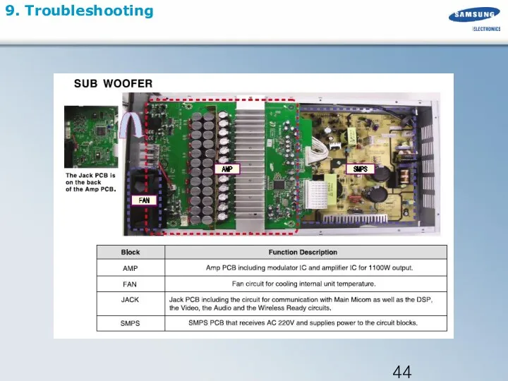
- 44. 9. Troubleshooting
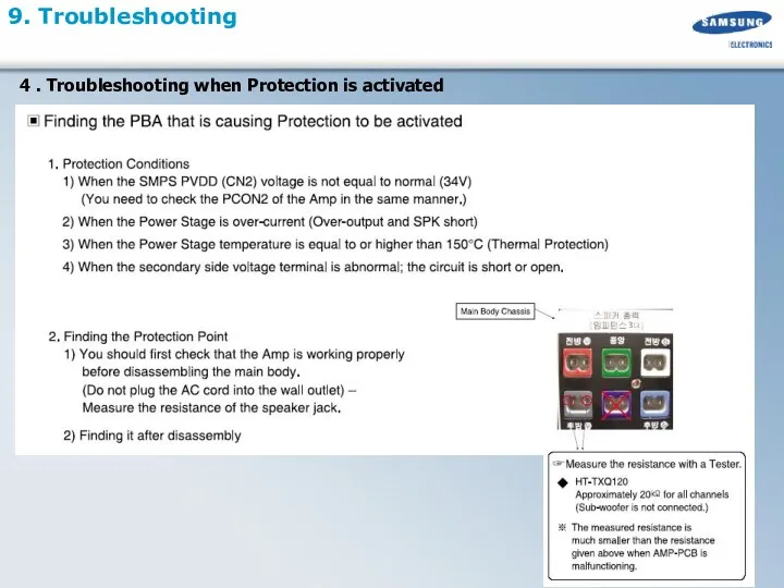
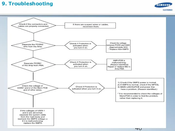
- 45. 9. Troubleshooting 4 . Troubleshooting when Protection is activated
- 46. 9. Troubleshooting
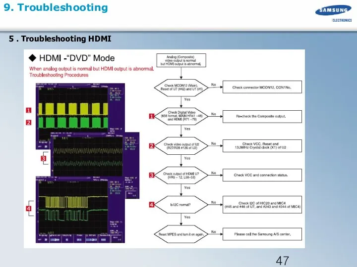
- 47. 9. Troubleshooting 5 . Troubleshooting HDMI
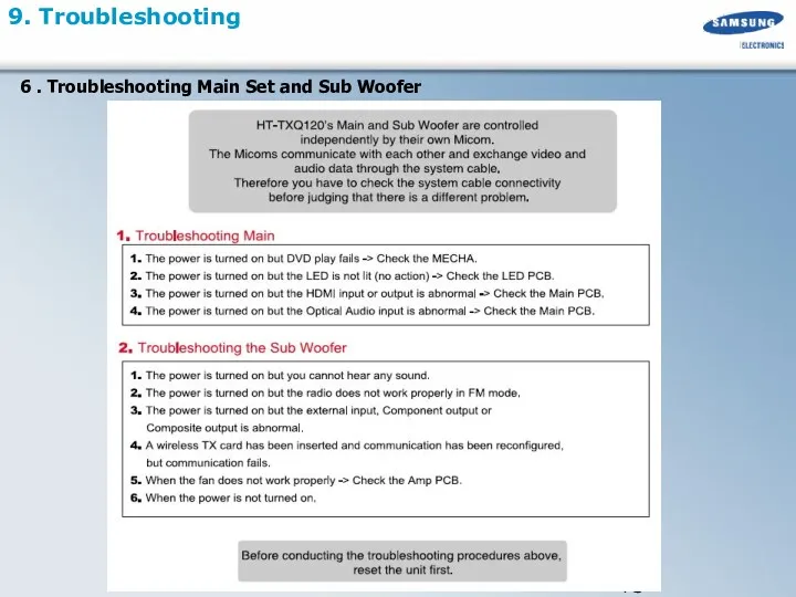
- 48. 9. Troubleshooting 6 . Troubleshooting Main Set and Sub Woofer
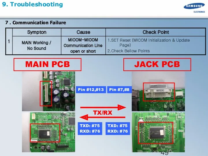
- 49. 9. Troubleshooting TXD: #75 RXD: #76 MAIN PCB JACK PCB TX/RX TXD: #75 RXD: #76 Pin
- 50. 9. Troubleshooting UIC1 MICOM #79 RESET SYSTEM RESET MIC4 MPEG #252 RESET RESET Insecure : It
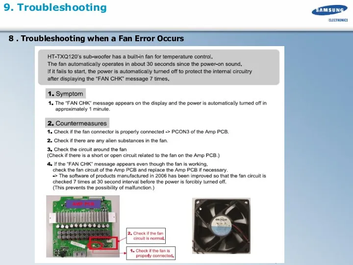
- 51. 9. Troubleshooting 8 . Troubleshooting when a Fan Error Occurs
- 53. Скачать презентацию
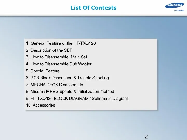
List Of Contests
1. General Feature of the HT-TXQ120
2. Description of the
List Of Contests
1. General Feature of the HT-TXQ120
2. Description of the
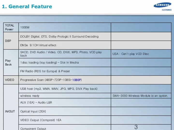
1. General Feature
1. General Feature
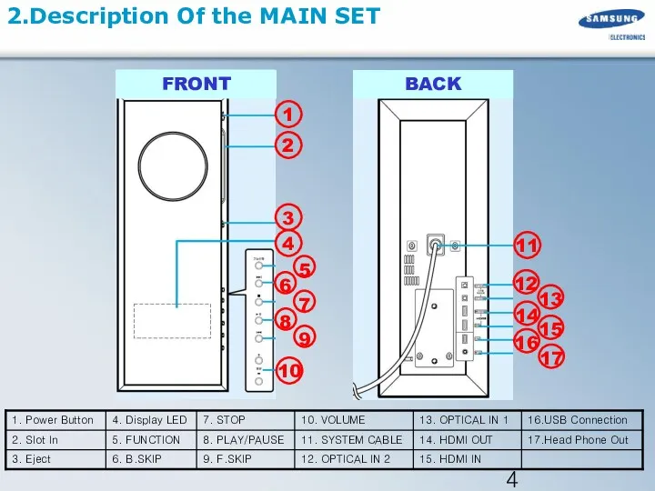
2.Description Of the MAIN SET
2.Description Of the MAIN SET
2.Description Of the MAIN SET
Function Description
2.Description Of the MAIN SET
Function Description
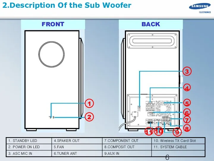
2.Description Of the Sub Woofer
2.Description Of the Sub Woofer
2.Description Of the Sub Woofer
Function Description
2.Description Of the Sub Woofer
Function Description
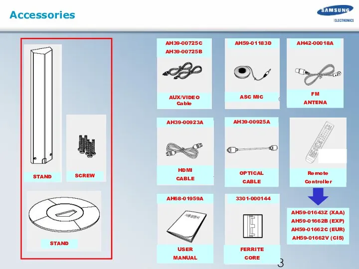
Accessories
Accessories
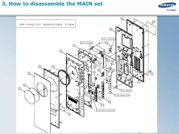
3. How to disassemble the MAIN set
3. How to disassemble the MAIN set
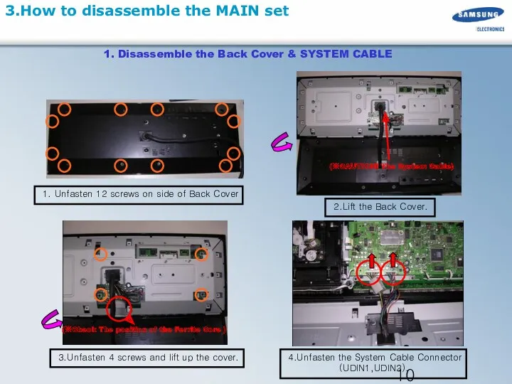
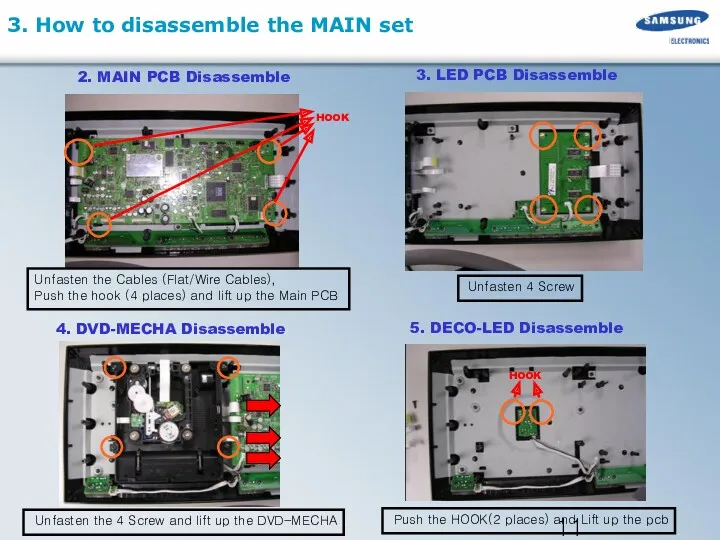
3.How to disassemble the MAIN set
1. Unfasten 12 screws on side
3.How to disassemble the MAIN set
1. Unfasten 12 screws on side
3. How to disassemble the MAIN set
Unfasten the Cables (Flat/Wire
3. How to disassemble the MAIN set
Unfasten the Cables (Flat/Wire
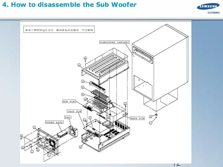
4. How to disassemble the Sub Woofer
4. How to disassemble the Sub Woofer
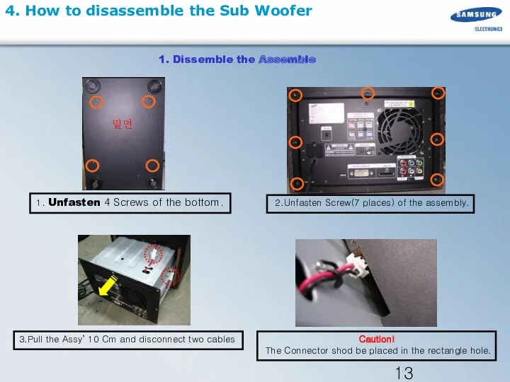
4. How to disassemble the Sub Woofer
1. Unfasten 4 Screws of
4. How to disassemble the Sub Woofer
1. Unfasten 4 Screws of
1. Unfasten Screw (10places)
2. Lift Up the Cover
2.Unfasten Assy’s Screw(3 places)
And
1. Unfasten Screw (10places)
2. Lift Up the Cover
2.Unfasten Assy’s Screw(3 places)
And
1. Unfasten Tuner Pack Screw(1 place)
5. Disassemble Jack /SMPS PCB
2.Unfasten Jack
1. Unfasten Tuner Pack Screw(1 place)
5. Disassemble Jack /SMPS PCB
2.Unfasten Jack
5.Special Feature – World First 1080P HTiB
SD
HD
HDMI : High-Definition Multimedia Interface
5.Special Feature – World First 1080P HTiB
SD
HD
HDMI : High-Definition Multimedia Interface
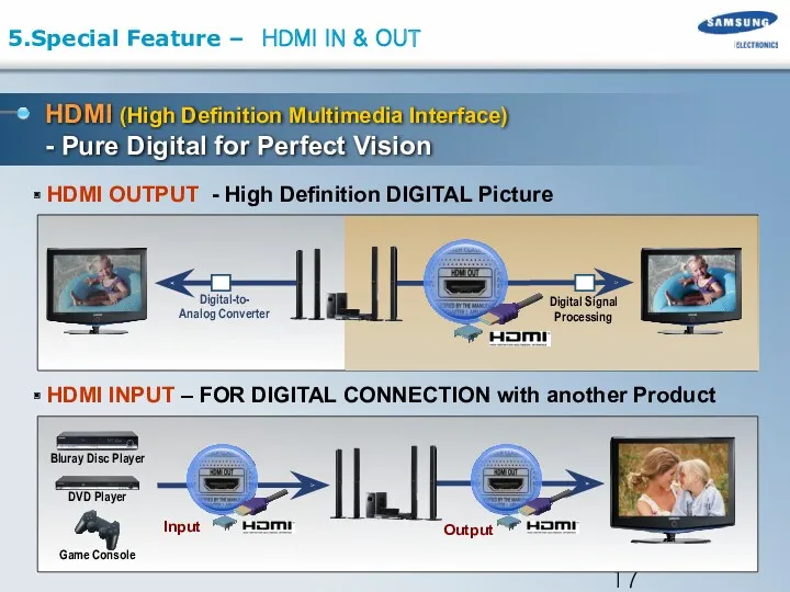
HDMI (High Definition Multimedia Interface)
- Pure Digital for Perfect Vision
HDMI
HDMI (High Definition Multimedia Interface)
- Pure Digital for Perfect Vision
HDMI
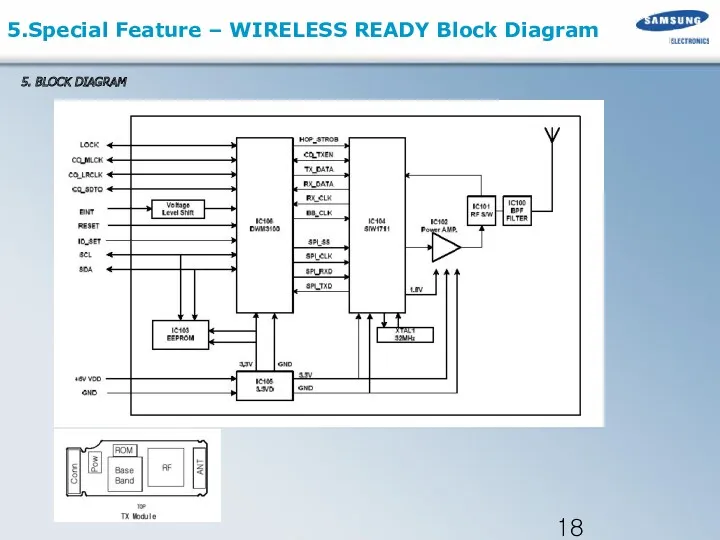
5. BLOCK DIAGRAM
5.Special Feature – WIRELESS READY Block Diagram
5. BLOCK DIAGRAM
5.Special Feature – WIRELESS READY Block Diagram
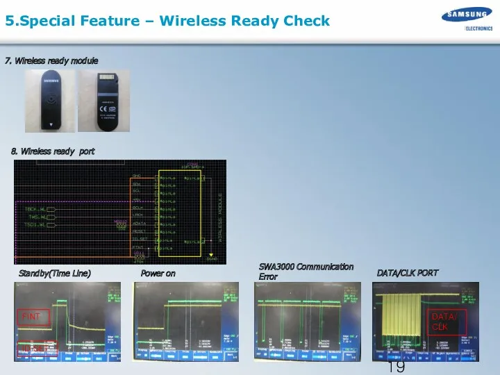
7. Wireless ready module
8. Wireless ready port
Standby(Time Line)
SWA3000 Communication Error
DATA/CLK PORT
Power
7. Wireless ready module
8. Wireless ready port
Standby(Time Line)
SWA3000 Communication Error
DATA/CLK PORT
Power
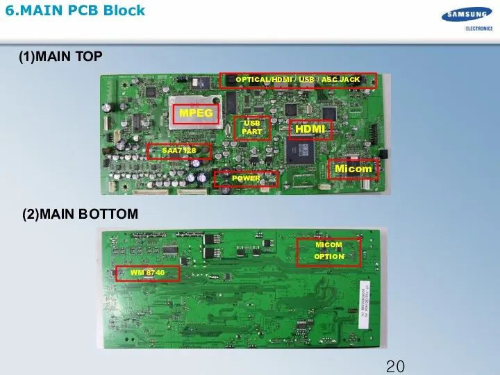
Micom
MPEG
6.MAIN PCB Block
OPTICAL/HDMI / USB / ASC JACK
WM 8746
MICOM
OPTION
POWER
SAA7128
USB PART
(1)MAIN TOP
(2)MAIN
Micom
MPEG
6.MAIN PCB Block
OPTICAL/HDMI / USB / ASC JACK
WM 8746
MICOM
OPTION
POWER
SAA7128
USB PART
(1)MAIN TOP
(2)MAIN
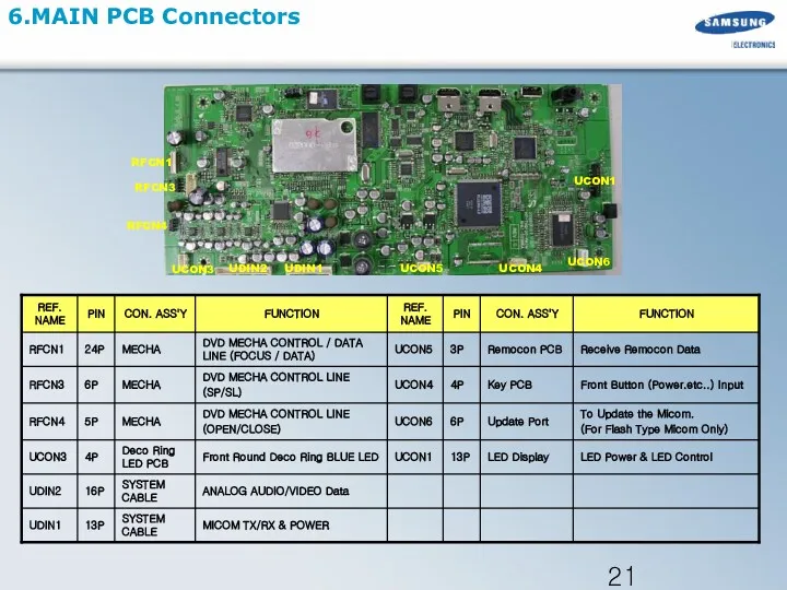
6.MAIN PCB Connectors
UCON3
UDIN2
UDIN1
RFCN4
RFCN3
RFCN1
UCON5
UCON4
UCON6
UCON1
6.MAIN PCB Connectors
UCON3
UDIN2
UDIN1
RFCN4
RFCN3
RFCN1
UCON5
UCON4
UCON6
UCON1
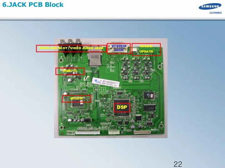
DSP
6.JACK PCB Block
WIRELESS SLOT / VIDEO AUDIO JACK
MICOM
MICOM
UPDATE
WM8775
SYSTEM JACK
DSP
6.JACK PCB Block
WIRELESS SLOT / VIDEO AUDIO JACK
MICOM
MICOM
UPDATE
WM8775
SYSTEM JACK
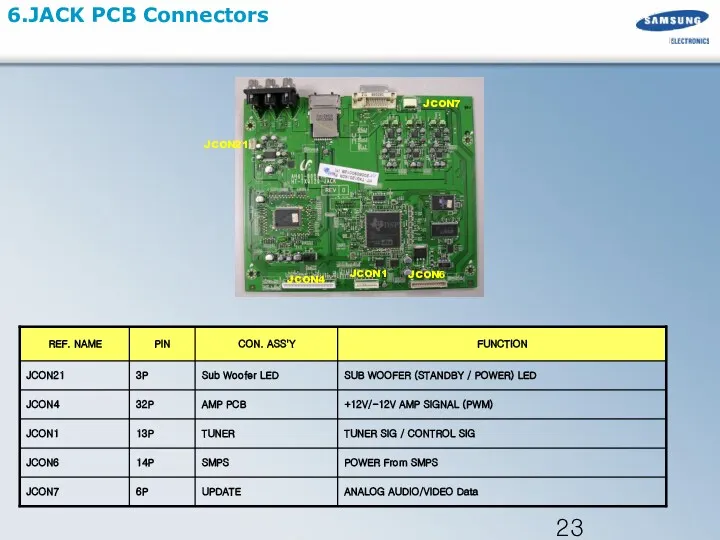
6.JACK PCB Connectors
JCON1
JCON4
JCON21
JCON6
JCON7
6.JACK PCB Connectors
JCON1
JCON4
JCON21
JCON6
JCON7
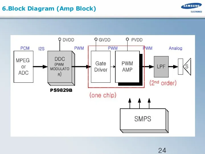
6.Block Diagram (Amp Block)
PS9829B
6.Block Diagram (Amp Block)
PS9829B
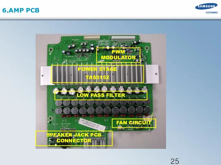
6.AMP PCB
PWM MODULATOR
LOW PASS FILTER
POWER STAGE
TAS5152
FAN CIRCUIT
SPEAKER JACK PCB CONNECTOR
6.AMP PCB
PWM MODULATOR
LOW PASS FILTER
POWER STAGE
TAS5152
FAN CIRCUIT
SPEAKER JACK PCB CONNECTOR
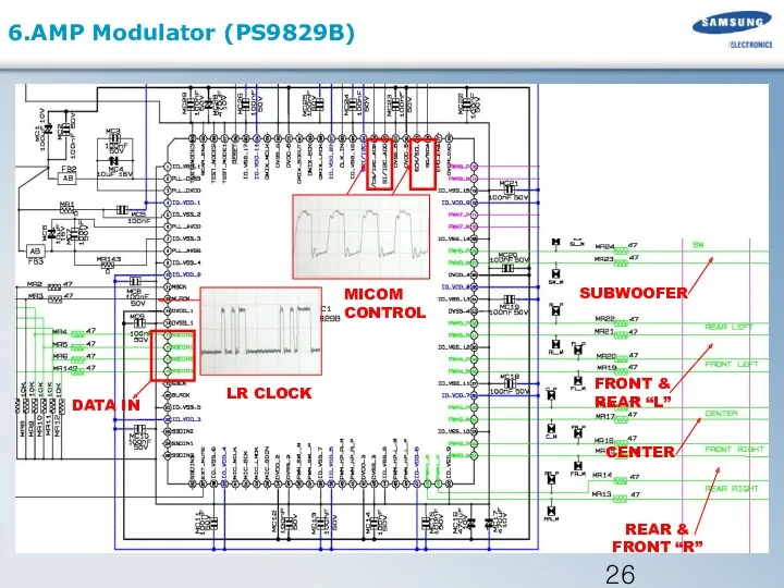
6.AMP Modulator (PS9829B)
FRONT & REAR “L”
SUBWOOFER
LR CLOCK
MICOM CONTROL
REAR & FRONT
6.AMP Modulator (PS9829B)
FRONT & REAR “L”
SUBWOOFER
LR CLOCK
MICOM CONTROL
REAR & FRONT
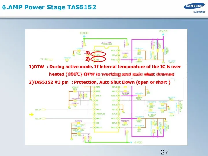
6.AMP Power Stage TAS5152
2)TAS5152 #3 pin : Protection, Auto Shut
6.AMP Power Stage TAS5152
2)TAS5152 #3 pin : Protection, Auto Shut
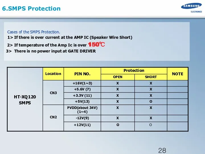
6.SMPS Protection
Cases of the SMPS Protection.
1> If there
6.SMPS Protection
Cases of the SMPS Protection.
1> If there
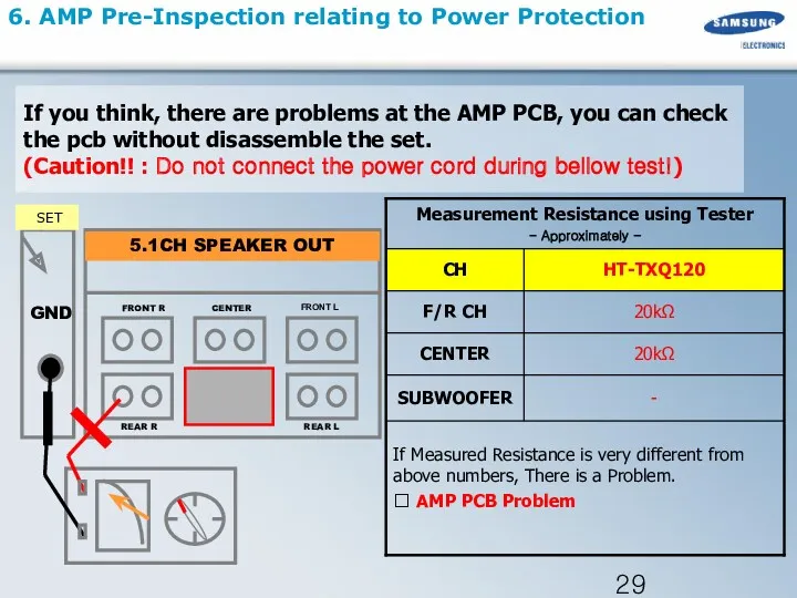
6. AMP Pre-Inspection relating to Power Protection
If you think, there are
6. AMP Pre-Inspection relating to Power Protection
If you think, there are
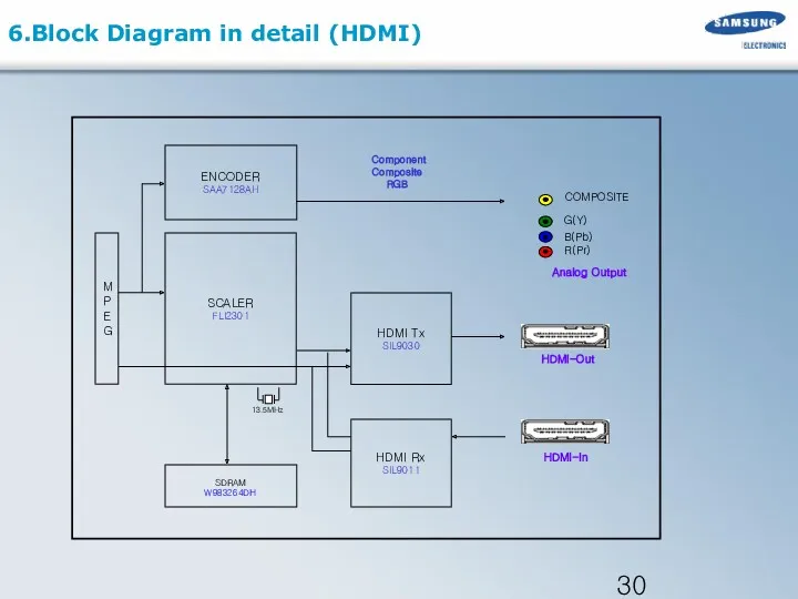
6.Block Diagram in detail (HDMI)
SCALER
FLI2301
SDRAM
W983264DH
HDMI Tx
SIL9030
13.5MHz
ENCODER
SAA7128AH
Component
HDMI-Out
Analog Output
Composite
RGB
HDMI-In
HDMI Rx
SIL9011
M
P
E
G
R(Pr)
G(Y)
B(Pb)
COMPOSITE
6.Block Diagram in detail (HDMI)
SCALER
FLI2301
SDRAM
W983264DH
HDMI Tx
SIL9030
13.5MHz
ENCODER
SAA7128AH
Component
HDMI-Out
Analog Output
Composite
RGB
HDMI-In
HDMI Rx
SIL9011
M
P
E
G
R(Pr)
G(Y)
B(Pb)
COMPOSITE
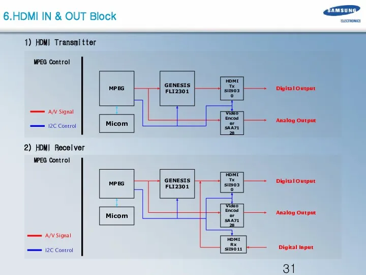
1) HDMI Transmitter
MPEG
HDMI Tx
SiI9030
HDMI Rx
SiI9011
Micom
GENESIS
FLI2301
Video
Encoder
SAA7128
Digital Output
Analog Output
A/V Signal
I2C Control
Digital Input
1) HDMI Transmitter
MPEG
HDMI Tx
SiI9030
HDMI Rx
SiI9011
Micom
GENESIS
FLI2301
Video
Encoder
SAA7128
Digital Output
Analog Output
A/V Signal
I2C Control
Digital Input
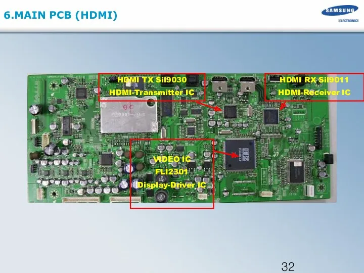
6.MAIN PCB (HDMI)
VIDEO IC
FLI2301
Display-Driver IC
HDMI TX Sil9030
HDMI-Transmitter IC
HDMI RX Sil9011
HDMI-Receiver IC
6.MAIN PCB (HDMI)
VIDEO IC
FLI2301
Display-Driver IC
HDMI TX Sil9030
HDMI-Transmitter IC
HDMI RX Sil9011
HDMI-Receiver IC
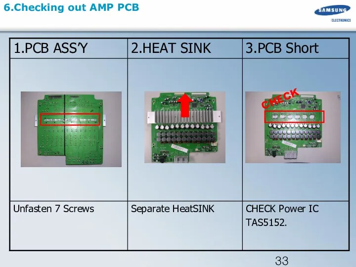
6.Checking out AMP PCB
CHECK
6.Checking out AMP PCB
CHECK
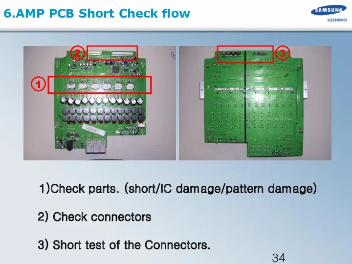
6.AMP PCB Short Check flow
1)Check parts. (short/IC damage/pattern damage)
6.AMP PCB Short Check flow
1)Check parts. (short/IC damage/pattern damage)
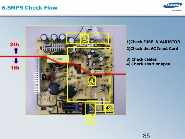
6.SMPS Check Flow
1)Check FUSE & VARISTOR
2)Check the AC Input Cord
3)
6.SMPS Check Flow
1)Check FUSE & VARISTOR
2)Check the AC Input Cord
3)
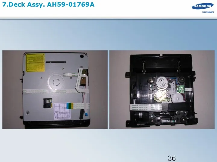
7.Deck Assy. AH59-01769A
7.Deck Assy. AH59-01769A
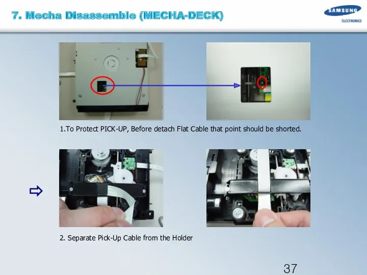
2. Separate Pick-Up Cable from the Holder
1.To Protect PICK-UP, Before detach
2. Separate Pick-Up Cable from the Holder
1.To Protect PICK-UP, Before detach
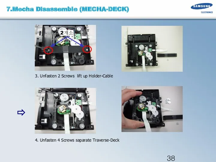
4. Unfasten 4 Screws saparate Traverse-Deck
3. Unfasten 2 Screws lift up
4. Unfasten 4 Screws saparate Traverse-Deck
3. Unfasten 2 Screws lift up
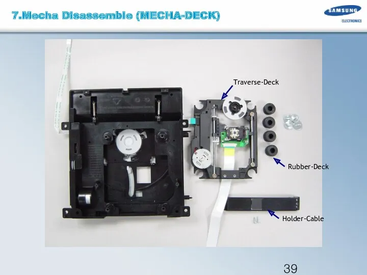
Traverse-Deck
Rubber-Deck
Holder-Cable
7.Mecha Disassemble (MECHA-DECK)
Traverse-Deck
Rubber-Deck
Holder-Cable
7.Mecha Disassemble (MECHA-DECK)
8.MICOM Initialization & Update
. Micom Reset
During STANDBY mode , push
8.MICOM Initialization & Update
. Micom Reset
During STANDBY mode , push
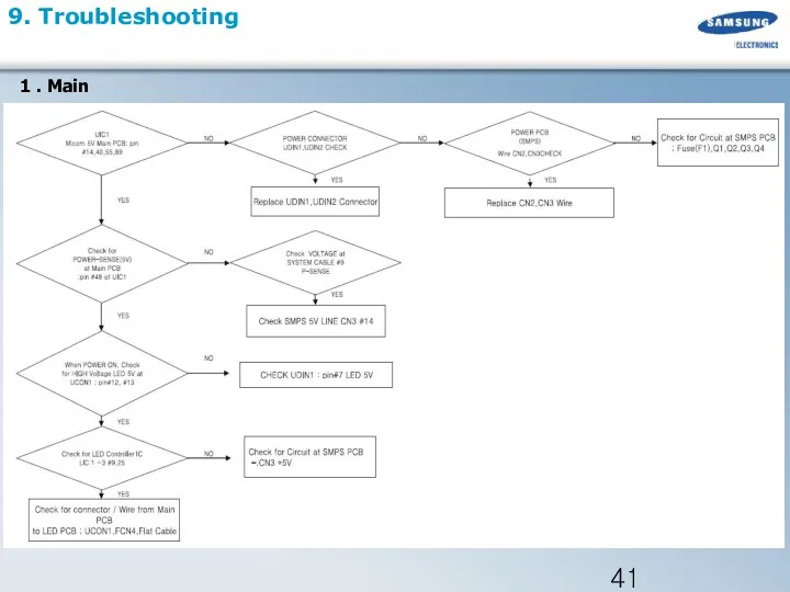
9. Troubleshooting
1 . Main
9. Troubleshooting
1 . Main
9. Troubleshooting
2 . Output
9. Troubleshooting
2 . Output
9. Troubleshooting
3 . Circuit Board Layout and Functions
9. Troubleshooting
3 . Circuit Board Layout and Functions
9. Troubleshooting
9. Troubleshooting
9. Troubleshooting
4 . Troubleshooting when Protection is activated
9. Troubleshooting
4 . Troubleshooting when Protection is activated
9. Troubleshooting
9. Troubleshooting
9. Troubleshooting
5 . Troubleshooting HDMI
9. Troubleshooting
5 . Troubleshooting HDMI
9. Troubleshooting
6 . Troubleshooting Main Set and Sub Woofer
9. Troubleshooting
6 . Troubleshooting Main Set and Sub Woofer
9. Troubleshooting
TXD: #75
RXD: #76
MAIN PCB
JACK PCB
TX/RX
TXD: #75
RXD: #76
Pin #12,#13
Pin #7,#8
7 .
9. Troubleshooting
TXD: #75
RXD: #76
MAIN PCB
JACK PCB
TX/RX
TXD: #75
RXD: #76
Pin #12,#13
Pin #7,#8
7 .
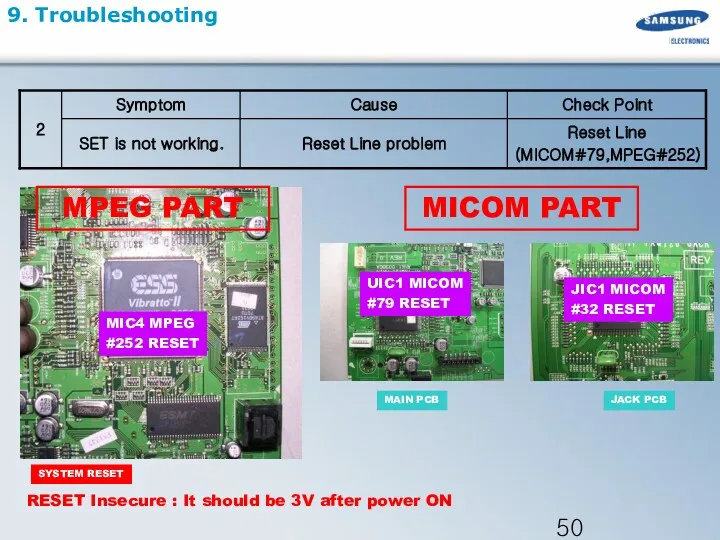
9. Troubleshooting
UIC1 MICOM
#79 RESET
SYSTEM RESET
MIC4 MPEG
#252 RESET
RESET Insecure : It should
9. Troubleshooting
UIC1 MICOM
#79 RESET
SYSTEM RESET
MIC4 MPEG
#252 RESET
RESET Insecure : It should
9. Troubleshooting
8 . Troubleshooting when a Fan Error Occurs
9. Troubleshooting
8 . Troubleshooting when a Fan Error Occurs
 Пожарная безопасность для дошкольников 5-7 лет
 Химия и фотография
 Примеры планировочных решений производственных участков
 Проектирование малогабаритной метеостанции
 публичная презентация общественности и профессиональному сообществу результатов педагогической деятельности
 Основы работы с табличным процессором MS Excel
 Замер статического уровня жидкости в скважине
 Родительское собрание Самостоятельность ребенка
 Материал для изготовления мебели. Древесноволокнистая плита (ДВП
 Описание материка Северная Америка
 Романский и готический стили
 Нуклеотиды и нуклеиновые кислоты. Строение ДНК и РНК
 Северо-Восточная Русь в XII – начале XIII веков
 Методы защиты энергооборудования от коррозии
 Лапароскопия в детской хирургии
 Транспорт и мировое хозяйство. 10 класс
 Құю өндірісінің технологиясы
 Современные строительные материалы
 Пародонт тіндерінің анатомиялық гистологиялық ерекшеліктері, құрылымы, қызметі
 Вітаю вас з днем народження мамо! Фотоальбом
 20230816_sera_himiya_9_klass
 Свиной цепень
 Образовательная область Коммуникация
 Углы, связанные с окружностью
 Цветущая ветка вишни
 Твердотельная электроника. Полевые транзисторы
 Эксперимент с произношением
 Транспорт. Виды транспорта