- Unconformities and Faults

Содержание
- 2. This presentation is to be completed in conjunction with exercise worksheet 5. Objectives: By the end
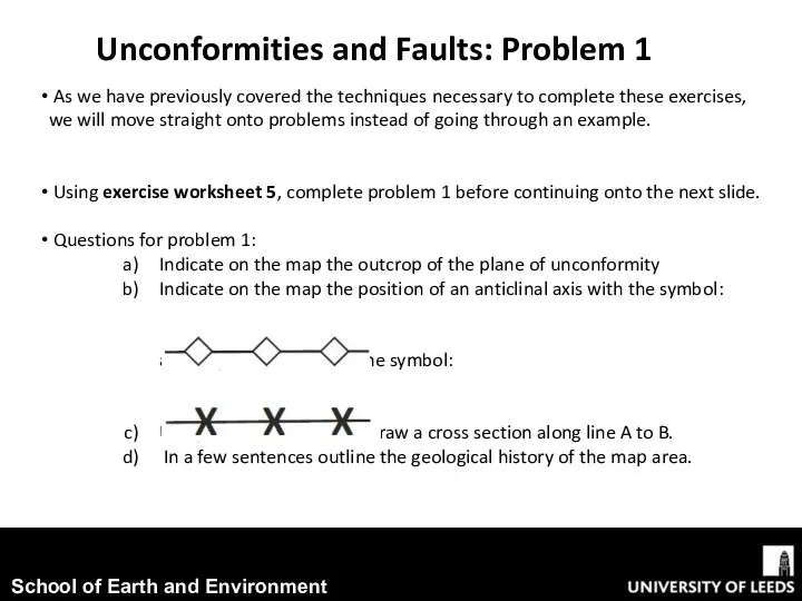
- 3. As we have previously covered the techniques necessary to complete these exercises, we will move straight
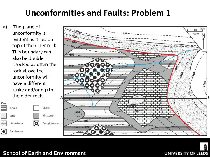
- 4. The plane of unconformity is evident as it lies on top of the older rock. This
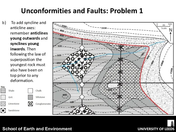
- 5. Unconformities and Faults: Problem 1 To add syncline and anticline axes: remember anticlines young outwards and
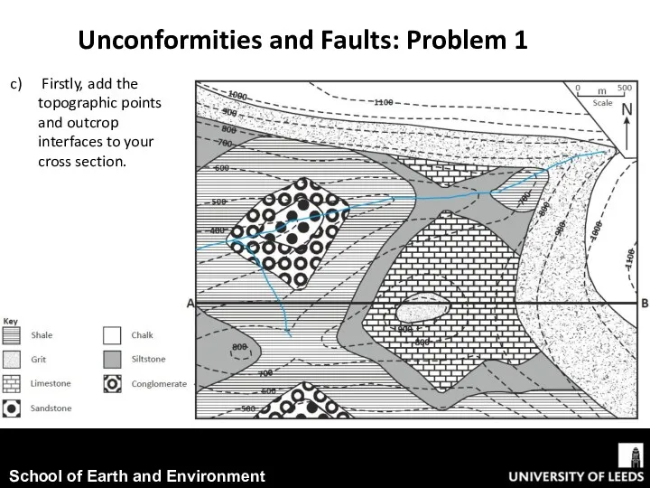
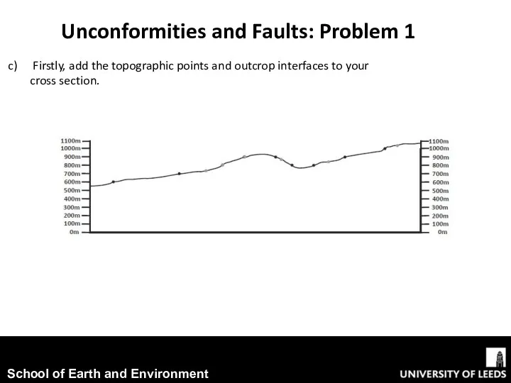
- 6. Unconformities and Faults: Problem 1 Firstly, add the topographic points and outcrop interfaces to your cross
- 7. Unconformities and Faults: Problem 1 Firstly, add the topographic points and outcrop interfaces to your cross
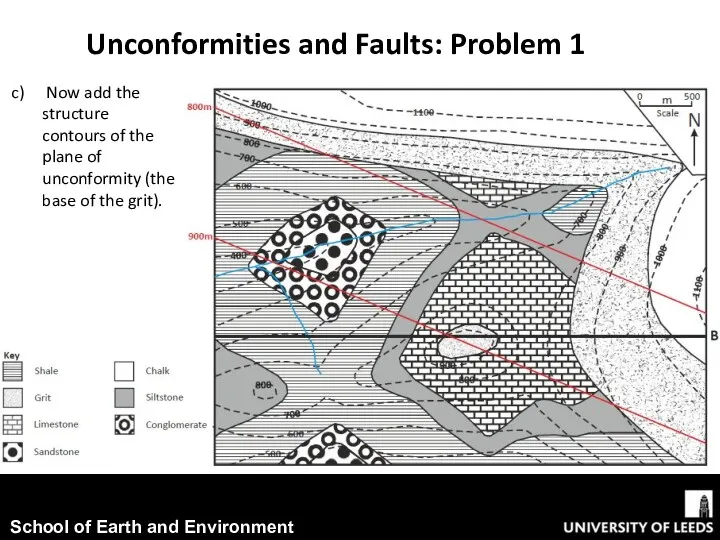
- 8. Unconformities and Faults: Problem 1 Now add the structure contours of the plane of unconformity (the
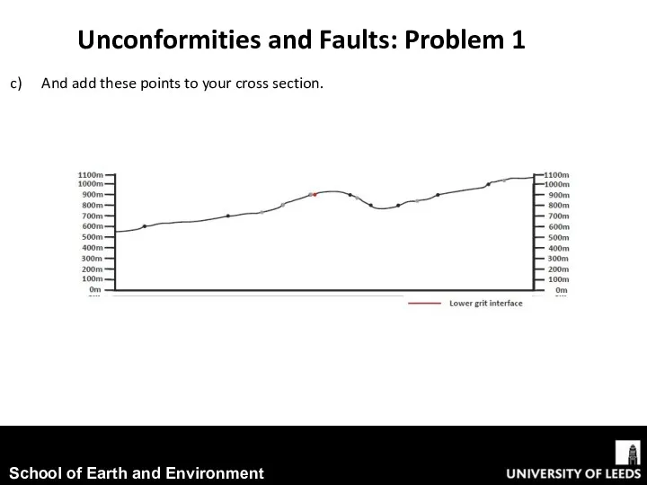
- 9. Unconformities and Faults: Problem 1 And add these points to your cross section.
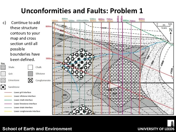
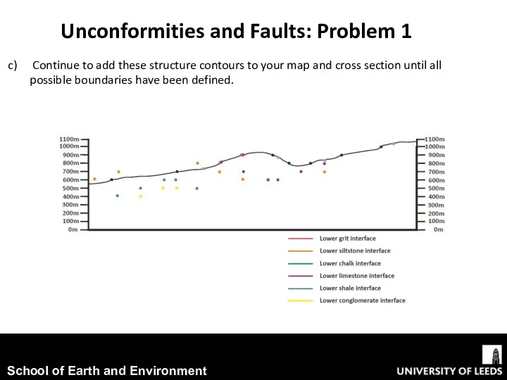
- 10. Continue to add these structure contours to your map and cross section until all possible boundaries
- 11. Unconformities and Faults: Problem 1 Continue to add these structure contours to your map and cross
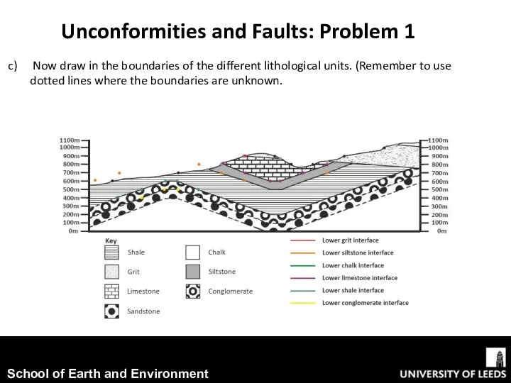
- 12. Unconformities and Faults: Problem 1 Now draw in the boundaries of the different lithological units. (Remember
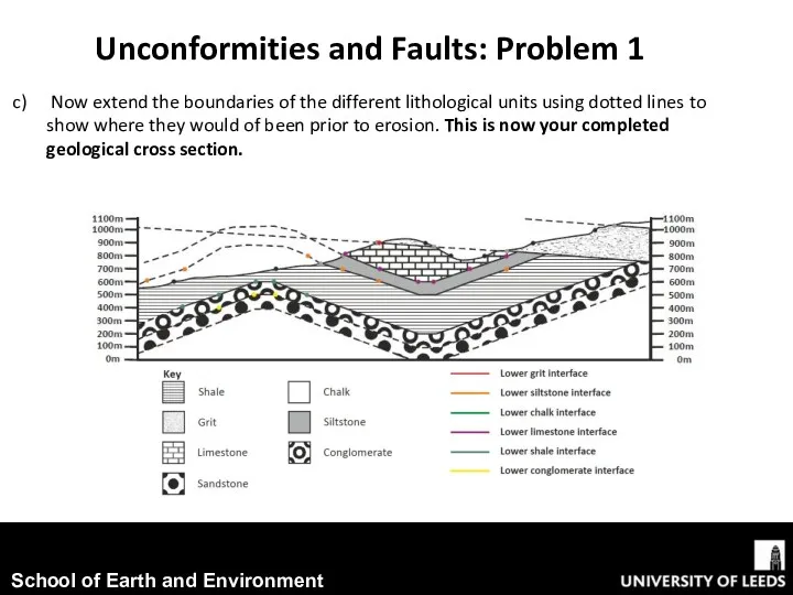
- 13. Unconformities and Faults: Problem 1 Now extend the boundaries of the different lithological units using dotted
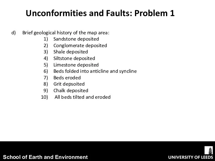
- 14. Unconformities and Faults: Problem 1 Brief geological history of the map area: Sandstone deposited Conglomerate deposited
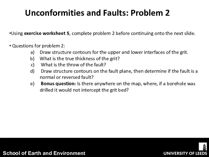
- 15. Unconformities and Faults: Problem 2 Using exercise worksheet 5, complete problem 2 before continuing onto the
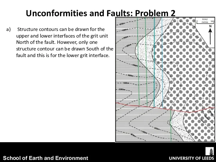
- 16. Unconformities and Faults: Problem 2 Structure contours can be drawn for the upper and lower interfaces
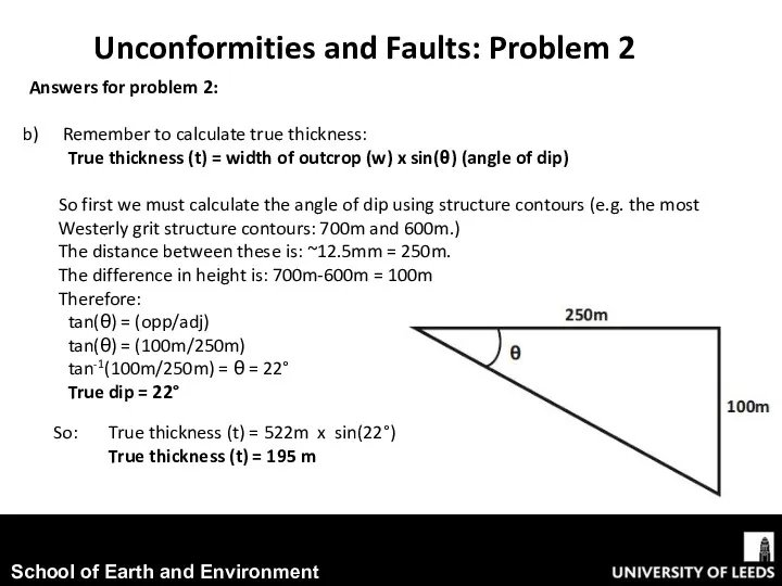
- 17. Unconformities and Faults: Problem 2 Answers for problem 2: Remember to calculate true thickness: True thickness
- 18. Unconformities and Faults: Problem 2 By assuming a constant dip of the beds we can add
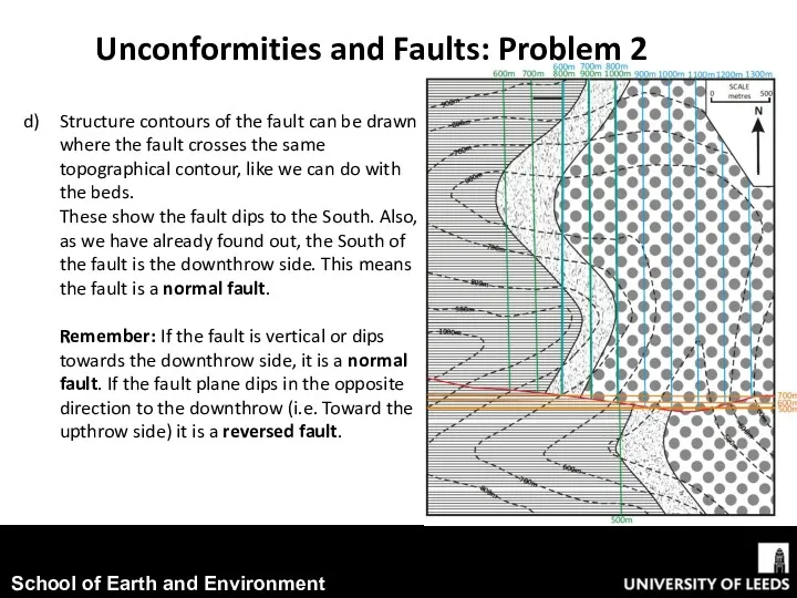
- 19. Unconformities and Faults: Problem 2 Structure contours of the fault can be drawn where the fault
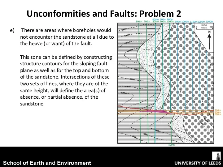
- 20. Unconformities and Faults: Problem 2 There are areas where boreholes would not encounter the sandstone at
- 22. Скачать презентацию
This presentation is to be completed in conjunction with exercise
This presentation is to be completed in conjunction with exercise
As we have previously covered the techniques necessary to complete
As we have previously covered the techniques necessary to complete
The plane of unconformity is evident as it lies on
The plane of unconformity is evident as it lies on
Unconformities and Faults: Problem 1
To add syncline and anticline axes:
Unconformities and Faults: Problem 1
To add syncline and anticline axes:
Unconformities and Faults: Problem 1
Firstly, add the topographic points and
Unconformities and Faults: Problem 1
Firstly, add the topographic points and
Unconformities and Faults: Problem 1
Firstly, add the topographic points and
Unconformities and Faults: Problem 1
Firstly, add the topographic points and
Unconformities and Faults: Problem 1
Now add the structure contours of
Unconformities and Faults: Problem 1
Now add the structure contours of
Unconformities and Faults: Problem 1
And add these points to your
Unconformities and Faults: Problem 1
And add these points to your
Continue to add these structure contours to your map and
Continue to add these structure contours to your map and
Unconformities and Faults: Problem 1
Continue to add these structure contours
Unconformities and Faults: Problem 1
Continue to add these structure contours
Unconformities and Faults: Problem 1
Now draw in the boundaries of
Unconformities and Faults: Problem 1
Now draw in the boundaries of
Unconformities and Faults: Problem 1
Now extend the boundaries of the
Unconformities and Faults: Problem 1
Now extend the boundaries of the
Unconformities and Faults: Problem 1
Brief geological history of the map
Unconformities and Faults: Problem 1
Brief geological history of the map
Unconformities and Faults: Problem 2
Using exercise worksheet 5, complete problem 2
Unconformities and Faults: Problem 2
Using exercise worksheet 5, complete problem 2
Unconformities and Faults: Problem 2
Structure contours can be drawn for
Unconformities and Faults: Problem 2
Structure contours can be drawn for
Unconformities and Faults: Problem 2
Answers for problem 2:
Remember to calculate
Unconformities and Faults: Problem 2
Answers for problem 2:
Remember to calculate

Unconformities and Faults: Problem 2
By assuming a constant dip of
Unconformities and Faults: Problem 2
By assuming a constant dip of
Unconformities and Faults: Problem 2
Structure contours of the fault can be
Unconformities and Faults: Problem 2
Structure contours of the fault can be
Unconformities and Faults: Problem 2
There are areas where boreholes would
Unconformities and Faults: Problem 2
There are areas where boreholes would
 презентация Готовность учителя к уроку
 Бу күшті қондырғының негізгі циклы (Ренкин циклы)
 Влажно-тепловая обработка. ВТО
 Презентация к уроку Режим и питание рек 6 класс
 Современные шовные материалы и область их применения
 Презентация по краеведению на тему Верните мне хозяина
 Культура раннего Средневековья
 Что надеть и взять с собой?. Необычные места России
 Mark Twain
 Pu-239
 Я и моя семья
 Nosorog
 Основы гемодинамики
 Методика разработки учебных программ по математике
 00011370_IBMF
 Онлайн викторина Своя игра
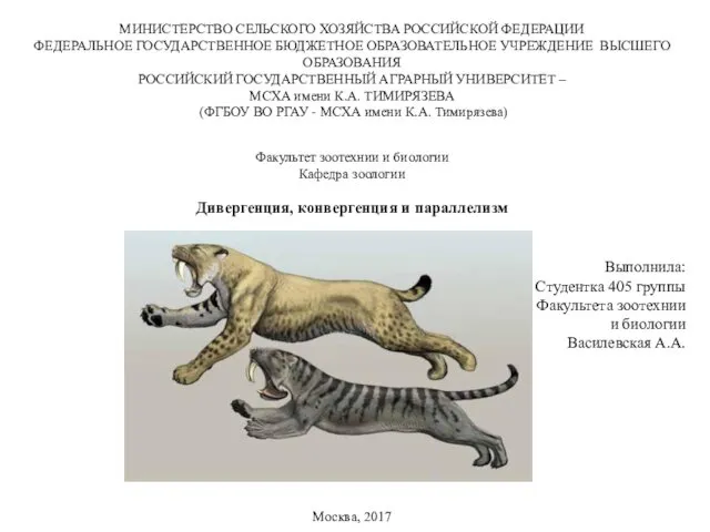 Дивергенция, конвергенция и параллелизм
 Робототехника
 Терапия, направленная на улучшение регенераторно-репаративных процессов. Лечение ишемического инсультa
 Конспект совместной образовательной деятельности воспитателей и детей старшего дошкольного возраста Экскурсия на почтовое отделение(с презентацией)
 Материал по краеведению Республики Адыгея
 Средства измерения и автоматизация
 Игра для педагогов Сто к одному
 Фонтанная и газлифтная эксплуатация скважин
 Famous people of Great Britain. Agatha Christie (15 September 1890 – 12 January 1976)
 Брейн-ринг!
 Великие портретисты прошлого
 Научно-техническое сопровождение при строительстве. Основные нормативно-справочные документы