- Rotordynamics

Содержание
- 2. Introduction Main Focus: Jet Engines Funding provided by NASA/Boeing, GE, MTU, P&W, Snecma and Rolls-Royce and
- 3. Overview of Rotordynamics Types of analyses Static analysis Complex Eigenvalue Whirl modes, Campbell diagrams Critical speed
- 4. Assumptions and Limitations Analysis performed in a stationary (inertial) coordinate system, i.e., non-rotating Models must be
- 5. Assumptions and Limitations Rotor axis is flexible, disks are rigid Critical speeds and modes are only
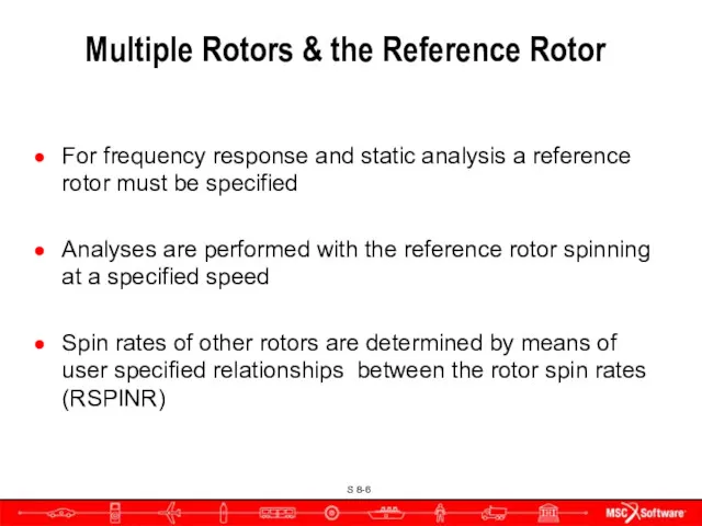
- 6. Multiple Rotors & the Reference Rotor For frequency response and static analysis a reference rotor must
- 7. Synchronous frequency-domain (complex modes and frequency response) analyses are performed relative to the reference rotor The
- 8. Input Overview
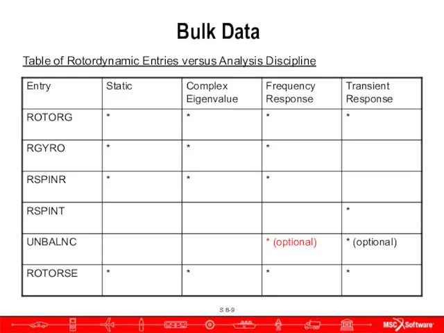
- 9. Bulk Data Table of Rotordynamic Entries versus Analysis Discipline
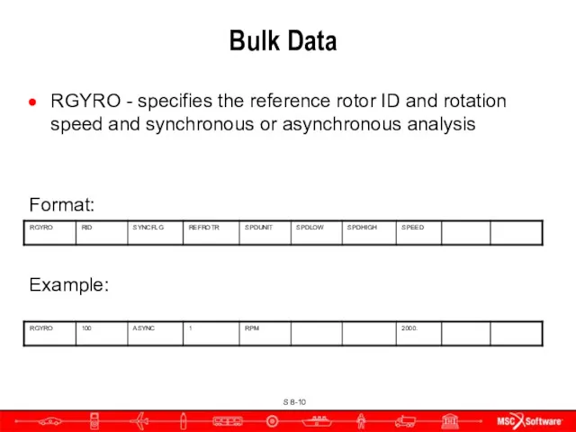
- 10. Bulk Data RGYRO - specifies the reference rotor ID and rotation speed and synchronous or asynchronous
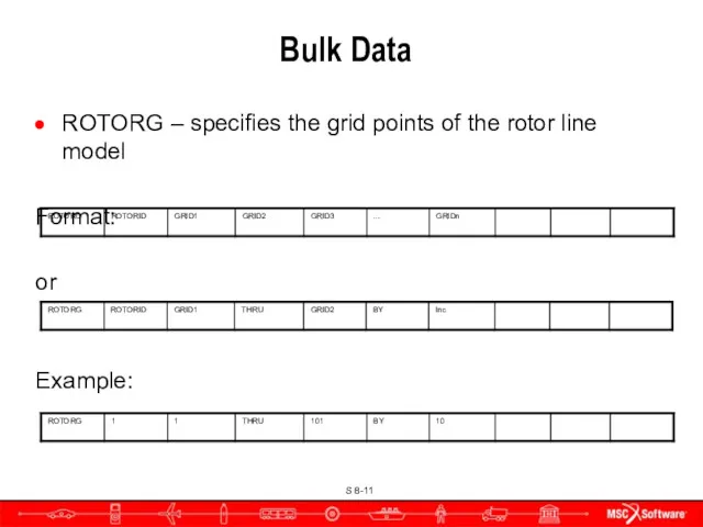
- 11. Bulk Data ROTORG – specifies the grid points of the rotor line model Format: or Example:
- 12. ROTORG Contents ROTORID Identification number for rotor GRIDi Grids comprising the rotor THRU Specifies a range
- 13. Rotor & Support Structure Connection Rotors specified using the ROTORG must employ rigid elements to decouple
- 14. Connection Schematic Example of Connection when using ROTORG G2 & RBAR/RBE2 not needed with ROTORSE Rotor
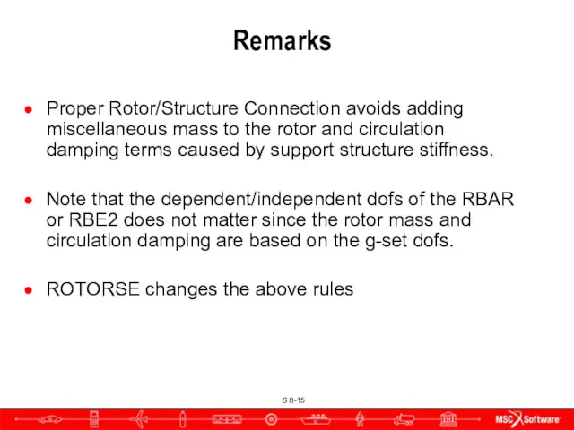
- 15. Remarks Proper Rotor/Structure Connection avoids adding miscellaneous mass to the rotor and circulation damping terms caused
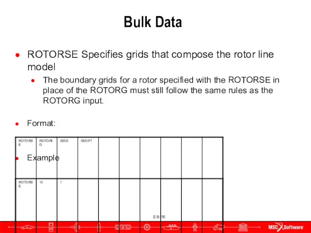
- 16. Bulk Data ROTORSE Specifies grids that compose the rotor line model The boundary grids for a
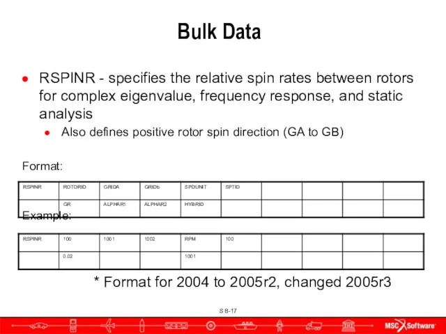
- 17. Bulk Data RSPINR - specifies the relative spin rates between rotors for complex eigenvalue, frequency response,
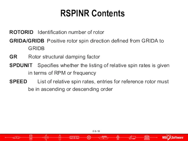
- 18. RSPINR Contents ROTORID Identification number of rotor GRIDA/GRIDB Positive rotor spin direction defined from GRIDA to
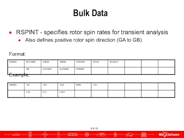
- 19. Bulk Data RSPINT - specifies rotor spin rates for transient analysis Also defines positive rotor spin
- 20. RSPINT Contents ROTORID Identification number of rotor GRIDA/GRIDB Positive rotor spin direction is defined from GRIDA
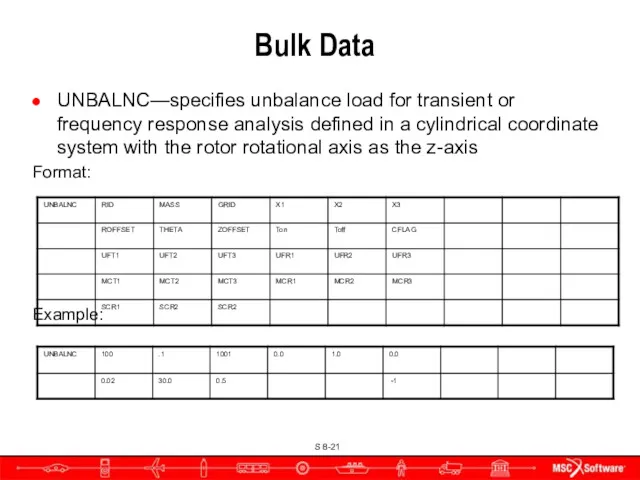
- 21. Bulk Data UNBALNC—specifies unbalance load for transient or frequency response analysis defined in a cylindrical coordinate
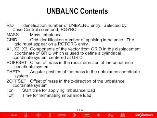
- 22. UNBALNC Contents RID Identification number of UNBALNC entry. Selected by Case Control command, RGYRO MASS Mass
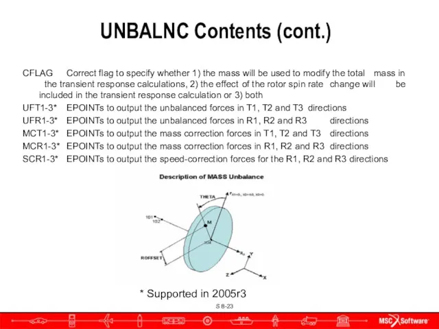
- 23. UNBALNC Contents (cont.) CFLAG Correct flag to specify whether 1) the mass will be used to
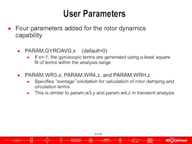
- 24. User Parameters Four parameters added for the rotor dynamics capability PARAM,GYROAVG,x (default=0) If x=-1, the gyroscopic
- 25. Some Applications of Rotordynamics
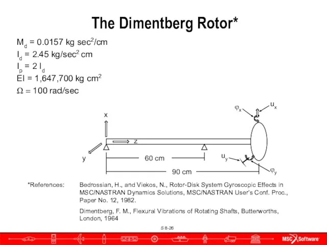
- 26. The Dimentberg Rotor* Md = 0.0157 kg sec2/cm Id = 2.45 kg/sec2 cm Ip = 2
- 27. Line Model w/o Superelements CBAR Elements with CONM2 100 at Node 10 Node 10 Rotor support
- 28. Rotor support points with either springs or constraints The Dimentberg Rotor
- 29. Comments Proper Rotor/Structure Connection avoids adding miscellaneous mass to the rotor and circulation damping terms caused
- 30. Connection for Rotor and Support Structure Rotor Support Structure RBAR or RBE2 Schematic Example of Connection
- 31. Bulk Data ROTORSE Specifies grids that compose the rotor line model The boundary grids for a
- 32. Rotordynamics Complex Eigenvalue Analyses Whirl Frequencies Critical Speeds Frequency Response Nonlinear Transient
- 33. Whirl Modes
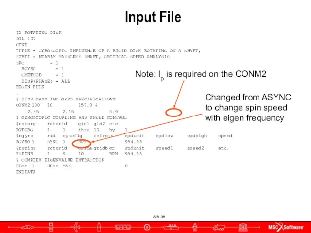
- 34. Input File ID ROTATING DISK SOL 107 CEND TITLE = GYROSCOPIC INFLUENCE OF A RIGID DISK
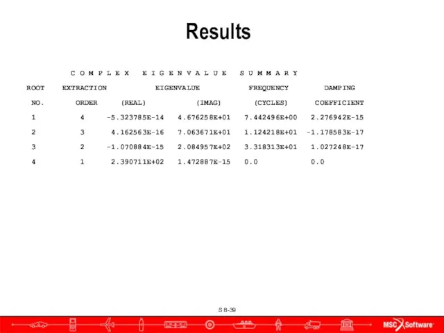
- 35. Results C O M P L E X E I G E N V A L
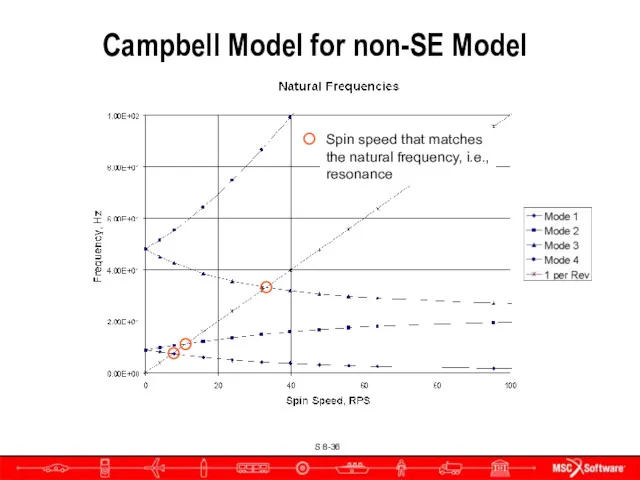
- 36. Campbell Model for non-SE Model Spin speed that matches the natural frequency, i.e., resonance
- 37. Critical Speeds
- 38. Input File ID ROTATING DISK SOL 107 CEND TITLE = GYROSCOPIC INFLUENCE OF A RIGID DISK
- 39. Results C O M P L E X E I G E N V A L
- 40. Critical Speeds on the Campbell Diagram 7.44 Hz 11.2 Hz 33.2 Hz
- 41. Frequency Response Analysis
- 42. Input File ID ROTATING DISK SOL 108 CEND TITLE = GYROSCOPIC INFLUENCE OF A RIGID DISK
- 43. $ DISK MASS AND GYRO SPECIFICATIONS CONM2 100 10 157.0-4 2.45 2.45 4.9 $ GYROSCOPIC COUPLING
- 44. Forward Whirl The forward whirl mode is excited
- 45. Nonlinear Transient Response
- 46. Out of Balance Excitation Dimentberg rotor to illustrate UNBALNC input
- 47. Input File ID QUAD4 MODEL TIME 1000 DIAG 8 $,15,56 SOL 129 CEND TITLE = QUAD4
- 48. Input File BEGIN BULK PARAM LGDISP 1 PARAM POST 0 PARAM PRGPST NO $ $ rotor
- 49. Results
- 50. Damping
- 51. New Damping Inputs Different forms of damping are now Accessible through Case Control command/bulk data entry
- 52. SEDAMP and RSDAMP Case Control Commands SEDAMP - Requests parameter and hybrid damping for superelements SEDMAP
- 53. Bulk Data DAMPING Entry Bulk Data Entry – DAMPING Format Example
- 54. Field Contents ID Damping entry identification number. (Integer > 0, no Default) G Structural damping coefficient,
- 55. Damping
- 56. Bulk Data HYBDAMP Entry Hybrid modal damping for direct dynamic solutions Specifies the eigenvalue extraction method
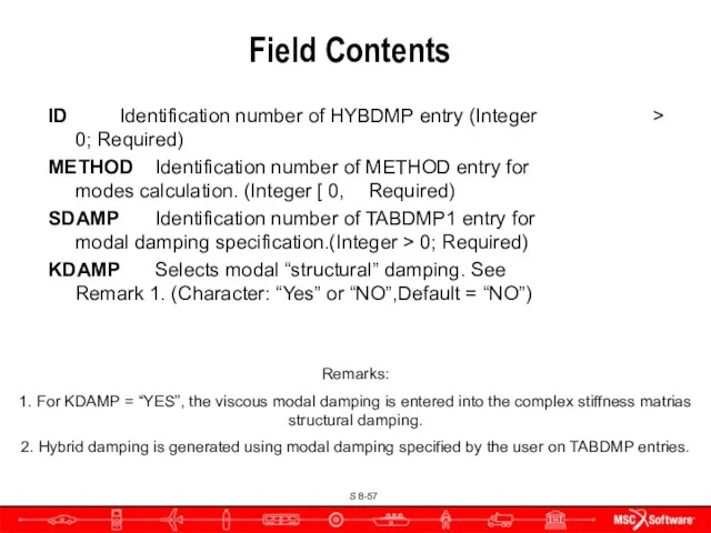
- 57. Field Contents ID Identification number of HYBDMP entry (Integer > 0; Required) METHOD Identification number of
- 58. Squeeze Film Damper for Nonlinear Force The squeeze film damper (SFD) was implemented as a nonlinear
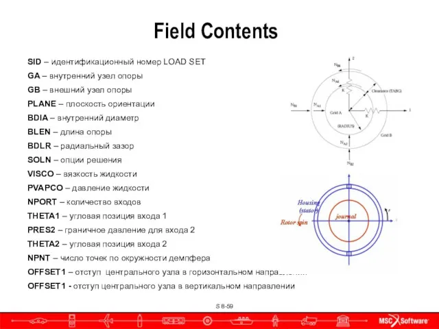
- 59. Field Contents SID – идентификационный номер LOAD SET GA – внутренний узел опоры GB – внешний
- 60. For better accuracy and to facilitate use in other solution sequences the NLRSFD was also implemented
- 61. Defines linear and nonlinear properties of a two-dimensional element (CBUSH2D entry). Stiffness, damping and Mass for
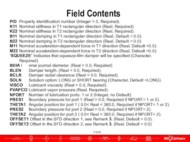
- 62. Field Contents PID Property identification number (Integer > 0, Required). K11 Nominal stiffness in T1 rectangular
- 63. Rotors and Aeroelasticity
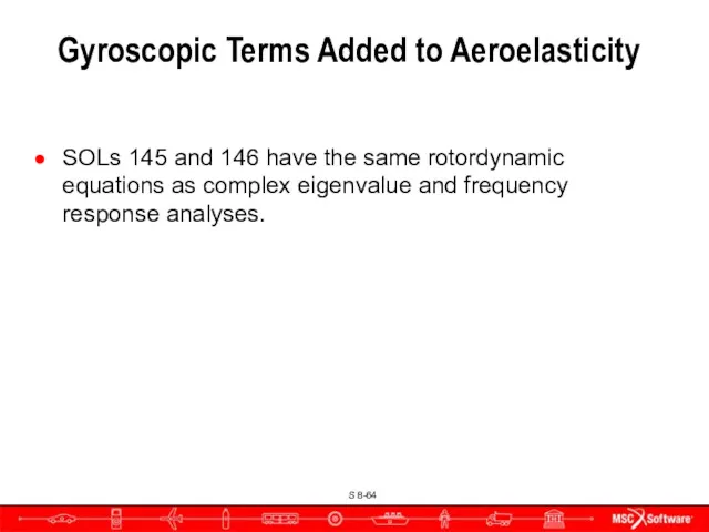
- 64. Gyroscopic Terms Added to Aeroelasticity SOLs 145 and 146 have the same rotordynamic equations as complex
- 65. FSW Full Model Transient Response Plan View Side View
- 66. Canard Control Surface Input Deflection Time, sec. Canard Relative Rotation, rad.
- 67. Pitch, Roll & Yaw Response Grid 90 Rotation Displacement, rad. Time, sec.
- 68. Campbell Diagrams
- 69. Campbell Diagrams Let’s first look at a 2 rotor model 1st Rotor support 1st Rotor support
- 70. Diagram for the 2 Rotor Model Run an asynchronous analysis with multiple subcases, import the complex
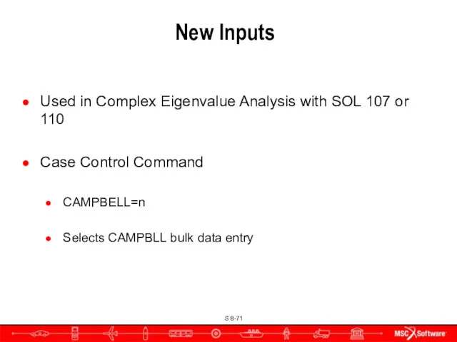
- 71. New Inputs Used in Complex Eigenvalue Analysis with SOL 107 or 110 Case Control Command CAMPBELL=n
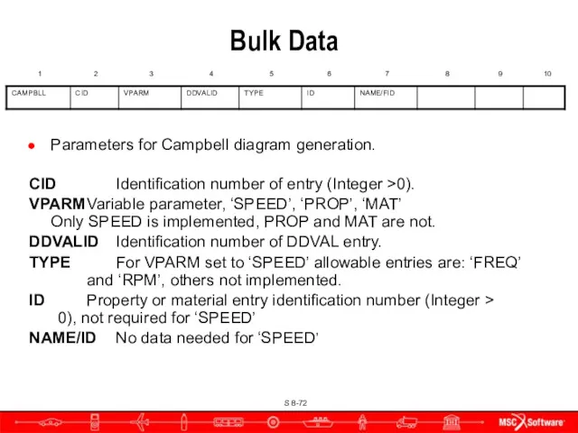
- 72. Bulk Data Parameters for Campbell diagram generation. CID Identification number of entry (Integer >0). VPARM Variable
- 74. Скачать презентацию
Introduction
Main Focus: Jet Engines
Funding provided by NASA/Boeing, GE, MTU, P&W, Snecma
Introduction
Main Focus: Jet Engines
Funding provided by NASA/Boeing, GE, MTU, P&W, Snecma
Overview of Rotordynamics
Types of analyses
Static analysis
Complex Eigenvalue
Whirl modes, Campbell diagrams
Critical
Overview of Rotordynamics
Types of analyses
Static analysis
Complex Eigenvalue
Whirl modes, Campbell diagrams
Critical
Assumptions and Limitations
Analysis performed in a stationary (inertial) coordinate system, i.e.,
Assumptions and Limitations
Analysis performed in a stationary (inertial) coordinate system, i.e.,
Assumptions and Limitations
Rotor axis is flexible, disks are rigid
Critical speeds and
Assumptions and Limitations
Rotor axis is flexible, disks are rigid
Critical speeds and
Multiple Rotors & the Reference Rotor
For frequency response and static analysis
Multiple Rotors & the Reference Rotor
For frequency response and static analysis
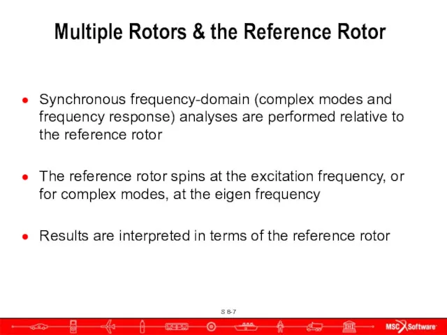
Synchronous frequency-domain (complex modes and frequency response) analyses are performed relative

Input Overview
Input Overview
Bulk Data
Table of Rotordynamic Entries versus Analysis Discipline
Bulk Data
Table of Rotordynamic Entries versus Analysis Discipline
Bulk Data
RGYRO - specifies the reference rotor ID and rotation speed
Bulk Data
RGYRO - specifies the reference rotor ID and rotation speed
Bulk Data
ROTORG – specifies the grid points of the rotor line
Bulk Data
ROTORG – specifies the grid points of the rotor line
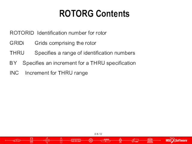
ROTORG Contents
ROTORID Identification number for rotor
GRIDi Grids comprising the rotor
THRU Specifies
ROTORG Contents
ROTORID Identification number for rotor
GRIDi Grids comprising the rotor
THRU Specifies
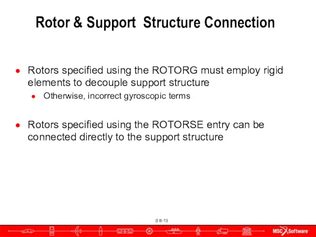
Rotor & Support Structure Connection
Rotors specified using the ROTORG must employ
Rotor & Support Structure Connection
Rotors specified using the ROTORG must employ
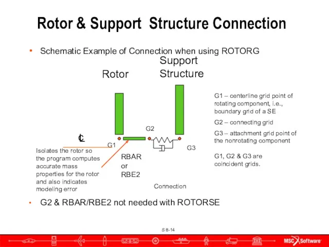
Connection
Schematic Example of Connection when using ROTORG
G2 & RBAR/RBE2 not
Connection
Schematic Example of Connection when using ROTORG
G2 & RBAR/RBE2 not
Remarks
Proper Rotor/Structure Connection avoids adding miscellaneous mass to the rotor and
Remarks
Proper Rotor/Structure Connection avoids adding miscellaneous mass to the rotor and
Bulk Data
ROTORSE Specifies grids that compose the rotor line model
The
Bulk Data
ROTORSE Specifies grids that compose the rotor line model
The
Bulk Data
RSPINR - specifies the relative spin rates between rotors for
Bulk Data
RSPINR - specifies the relative spin rates between rotors for
RSPINR Contents
ROTORID Identification number of rotor
GRIDA/GRIDB Positive rotor spin direction defined from GRIDA
RSPINR Contents
ROTORID Identification number of rotor
GRIDA/GRIDB Positive rotor spin direction defined from GRIDA
Bulk Data
RSPINT - specifies rotor spin rates for transient analysis
Also
Bulk Data
RSPINT - specifies rotor spin rates for transient analysis
Also
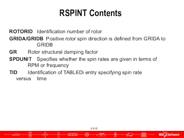
RSPINT Contents
ROTORID Identification number of rotor
GRIDA/GRIDB Positive rotor spin direction is defined from
RSPINT Contents
ROTORID Identification number of rotor
GRIDA/GRIDB Positive rotor spin direction is defined from
Bulk Data
UNBALNC—specifies unbalance load for transient or frequency response analysis defined
Bulk Data
UNBALNC—specifies unbalance load for transient or frequency response analysis defined
UNBALNC Contents
RID Identification number of UNBALNC entry. Selected by Case Control command,
UNBALNC Contents
RID Identification number of UNBALNC entry. Selected by Case Control command,
UNBALNC Contents (cont.)
CFLAG Correct flag to specify whether 1) the mass will
UNBALNC Contents (cont.)
CFLAG Correct flag to specify whether 1) the mass will
User Parameters
Four parameters added for the rotor dynamics capability
PARAM,GYROAVG,x (default=0)
If x=-1,
User Parameters
Four parameters added for the rotor dynamics capability
PARAM,GYROAVG,x (default=0)
If x=-1,
Some Applications of Rotordynamics
Some Applications of Rotordynamics
The Dimentberg Rotor*
Md = 0.0157 kg sec2/cm
Id = 2.45 kg/sec2 cm
Ip
The Dimentberg Rotor*
Md = 0.0157 kg sec2/cm
Id = 2.45 kg/sec2 cm
Ip
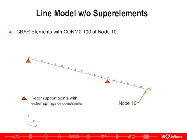
Line Model w/o Superelements
CBAR Elements with CONM2 100 at Node
Line Model w/o Superelements
CBAR Elements with CONM2 100 at Node
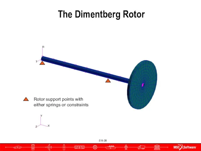
Rotor support points with either springs or constraints
The Dimentberg Rotor
Rotor support points with either springs or constraints
The Dimentberg Rotor
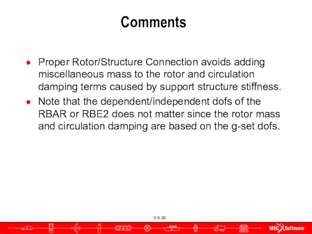
Comments
Proper Rotor/Structure Connection avoids adding miscellaneous mass to the rotor and
Comments
Proper Rotor/Structure Connection avoids adding miscellaneous mass to the rotor and
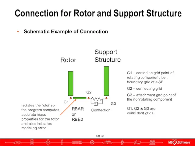
Connection for Rotor and Support Structure
Rotor
Support Structure
RBAR or RBE2
Schematic Example of
Connection for Rotor and Support Structure
Rotor
Support Structure
RBAR or RBE2
Schematic Example of

Bulk Data
ROTORSE Specifies grids that compose the rotor line model
The
Bulk Data
ROTORSE Specifies grids that compose the rotor line model
The
Rotordynamics
Complex Eigenvalue Analyses
Whirl Frequencies
Critical Speeds
Frequency Response
Nonlinear Transient
Rotordynamics
Complex Eigenvalue Analyses
Whirl Frequencies
Critical Speeds
Frequency Response
Nonlinear Transient
Whirl Modes
Whirl Modes
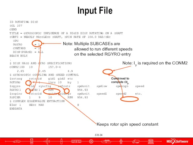
Input File
ID ROTATING DISK
SOL 107
CEND
TITLE = GYROSCOPIC INFLUENCE OF A RIGID
Input File
ID ROTATING DISK
SOL 107
CEND
TITLE = GYROSCOPIC INFLUENCE OF A RIGID
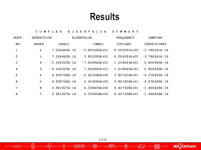
Results
C O M P L E X E I G
Results
C O M P L E X E I G
Campbell Model for non-SE Model
Spin speed that matches the natural frequency,
Campbell Model for non-SE Model
Spin speed that matches the natural frequency,

Critical Speeds
Critical Speeds
Input File
ID ROTATING DISK
SOL 107
CEND
TITLE = GYROSCOPIC INFLUENCE OF A RIGID
Input File
ID ROTATING DISK
SOL 107
CEND
TITLE = GYROSCOPIC INFLUENCE OF A RIGID
Results
C O M P L E X E I G
Results
C O M P L E X E I G
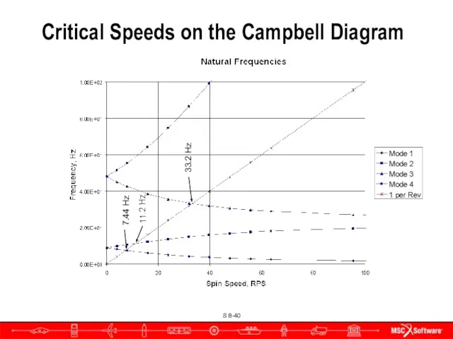
Critical Speeds on the Campbell Diagram
7.44 Hz
11.2 Hz
33.2 Hz
Critical Speeds on the Campbell Diagram
7.44 Hz
11.2 Hz
33.2 Hz
Frequency Response Analysis
Frequency Response Analysis
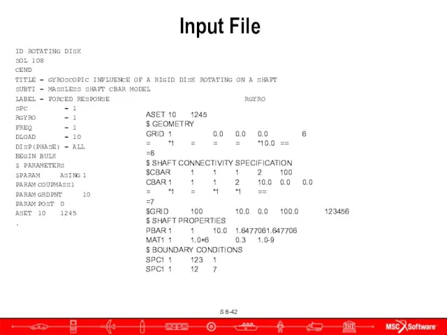
Input File
ID ROTATING DISK
SOL 108
CEND
TITLE = GYROSCOPIC INFLUENCE OF A RIGID
Input File
ID ROTATING DISK
SOL 108
CEND
TITLE = GYROSCOPIC INFLUENCE OF A RIGID
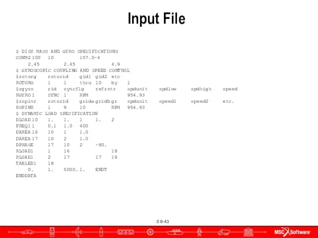
$ DISK MASS AND GYRO SPECIFICATIONS
CONM2 100 10 157.0-4
2.45 2.45 4.9
$ GYROSCOPIC COUPLING AND SPEED CONTROL
$rotorg rotorid gid1 gid2 etc
ROTORG 1 1 thru 10 by 1
$rgyro rid syncflg refrotr spdunit spdlow spdhigh speed
RGYRO 1 SYNC 1 RPM 954.93
$rspinr rotorid grida gridb gr spdunit speed1 speed2 etc.
RSPINR 1 9 10 RPM 954.93
$
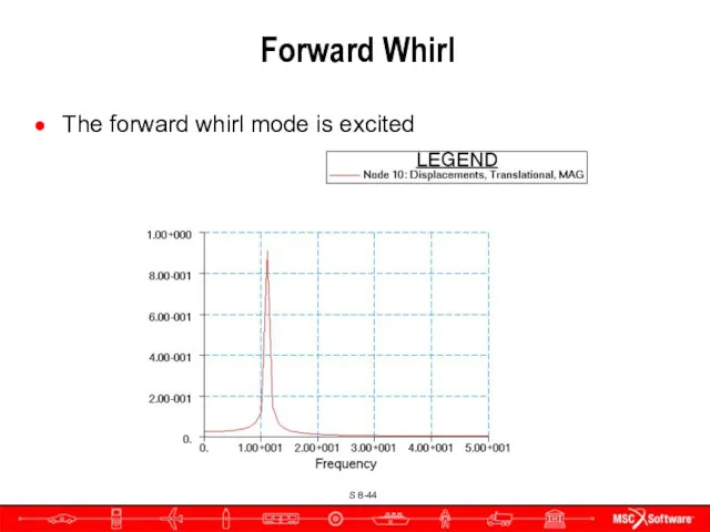
Forward Whirl
The forward whirl mode is excited
Forward Whirl
The forward whirl mode is excited
Nonlinear Transient Response
Nonlinear Transient Response
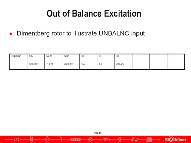
Out of Balance Excitation
Dimentberg rotor to illustrate UNBALNC input
Out of Balance Excitation
Dimentberg rotor to illustrate UNBALNC input
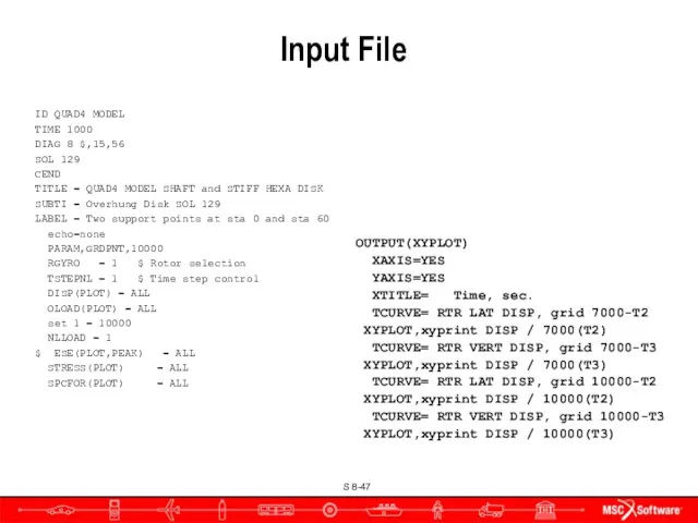
Input File
ID QUAD4 MODEL
TIME 1000
DIAG 8 $,15,56
SOL 129
CEND
TITLE = QUAD4 MODEL
Input File
ID QUAD4 MODEL
TIME 1000
DIAG 8 $,15,56
SOL 129
CEND
TITLE = QUAD4 MODEL
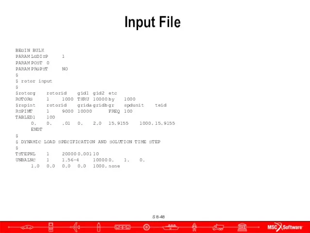
Input File
BEGIN BULK
PARAM LGDISP 1
PARAM POST 0
PARAM PRGPST NO
$
$ rotor input
$
$rotorg rotorid gid1 gid2 etc
ROTORG 1 1000 THRU 10000 by 1000
$rspint rotorid grida gridb gr spdunit teid
RSPINT 1 9000 10000 FREQ 100
TABLED1 100
0. 0. .01 0. 2.0 15.9155 1000. 15.9155
ENDT
$
$ DYNAMIC LOAD SPECIFICATION AND SOLUTION TIME
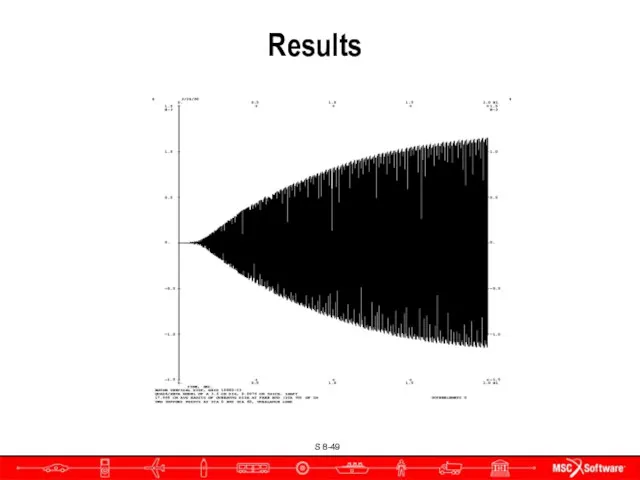
Results
Results
Damping
Damping
New Damping Inputs
Different forms of damping are now
Accessible through Case
New Damping Inputs
Different forms of damping are now
Accessible through Case
SEDAMP and RSDAMP Case Control Commands
SEDAMP - Requests parameter and hybrid
SEDAMP and RSDAMP Case Control Commands
SEDAMP - Requests parameter and hybrid
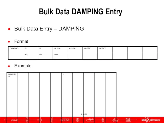
Bulk Data DAMPING Entry
Bulk Data Entry – DAMPING
Format
Example
Bulk Data DAMPING Entry
Bulk Data Entry – DAMPING
Format
Example
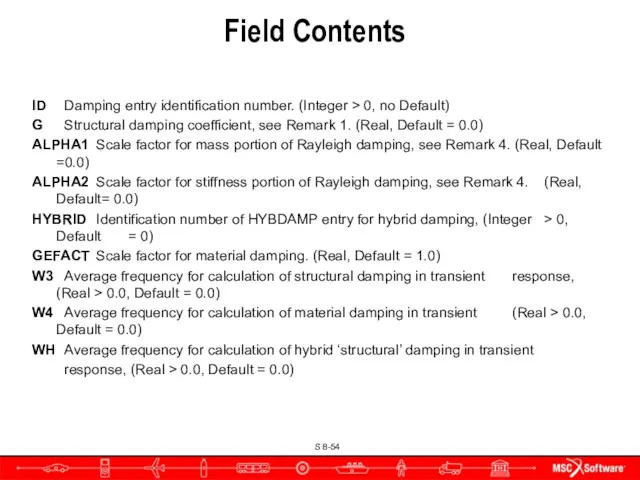
Field Contents
ID Damping entry identification number. (Integer > 0, no Default)
G
Field Contents
ID Damping entry identification number. (Integer > 0, no Default)
G
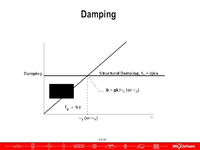
Damping
Damping
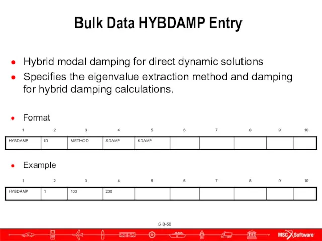
Bulk Data HYBDAMP Entry
Hybrid modal damping for direct dynamic solutions
Specifies the
Bulk Data HYBDAMP Entry
Hybrid modal damping for direct dynamic solutions
Specifies the
Field Contents
ID Identification number of HYBDMP entry (Integer > 0; Required)
METHOD
Field Contents
ID Identification number of HYBDMP entry (Integer > 0; Required)
METHOD
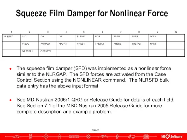
Squeeze Film Damper for Nonlinear Force
The squeeze film damper (SFD) was
Squeeze Film Damper for Nonlinear Force
The squeeze film damper (SFD) was
Field Contents
SID – идентификационный номер LOAD SET
GA – внутренний узел опоры
GB
Field Contents
SID – идентификационный номер LOAD SET
GA – внутренний узел опоры
GB
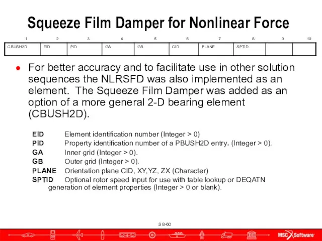
For better accuracy and to facilitate use in other solution sequences
For better accuracy and to facilitate use in other solution sequences
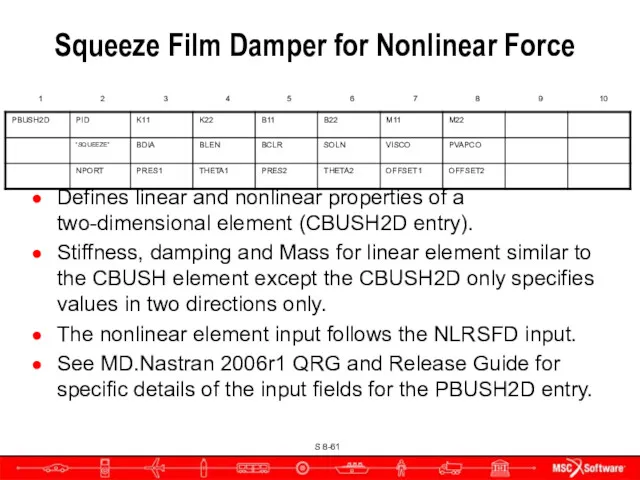
Defines linear and nonlinear properties of a two-dimensional element (CBUSH2D entry).
Stiffness,
Defines linear and nonlinear properties of a two-dimensional element (CBUSH2D entry).
Stiffness,
Field Contents
PID Property identification number (Integer > 0, Required).
K11 Nominal stiffness in
Field Contents
PID Property identification number (Integer > 0, Required).
K11 Nominal stiffness in
Rotors and Aeroelasticity
Rotors and Aeroelasticity
Gyroscopic Terms Added to Aeroelasticity
SOLs 145 and 146 have the same
Gyroscopic Terms Added to Aeroelasticity
SOLs 145 and 146 have the same
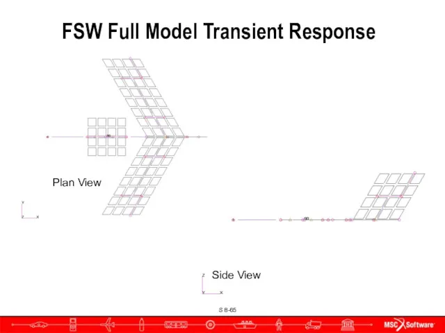
FSW Full Model Transient Response
Plan View
Side View
FSW Full Model Transient Response
Plan View
Side View
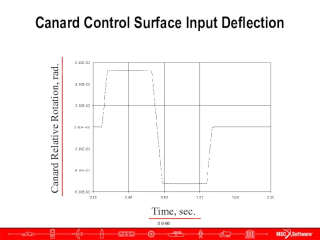
Canard Control Surface Input Deflection
Time, sec.
Canard Relative Rotation, rad.
Canard Control Surface Input Deflection
Time, sec.
Canard Relative Rotation, rad.
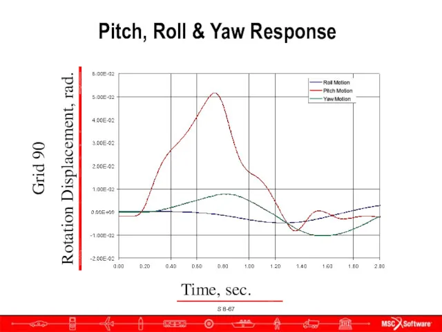
Pitch, Roll & Yaw Response
Grid 90
Rotation Displacement, rad.
Time, sec.
Pitch, Roll & Yaw Response
Grid 90
Rotation Displacement, rad.
Time, sec.

Campbell Diagrams
Campbell Diagrams
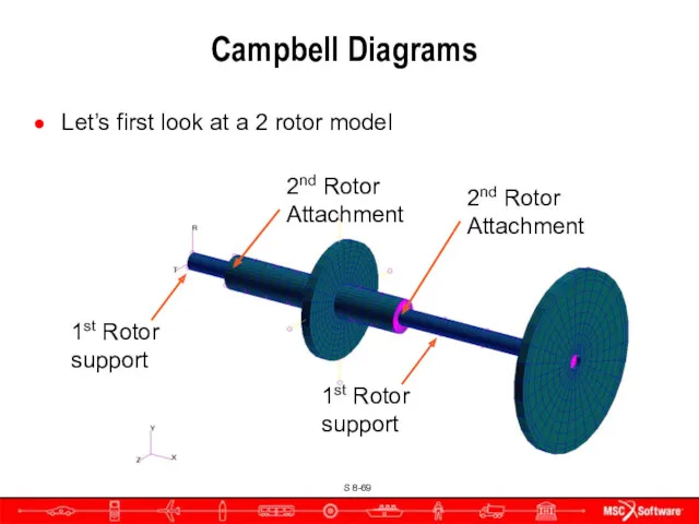
Campbell Diagrams
Let’s first look at a 2 rotor model
1st Rotor support
1st
Campbell Diagrams
Let’s first look at a 2 rotor model
1st Rotor support
1st
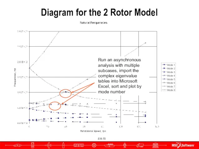
Diagram for the 2 Rotor Model
Run an asynchronous analysis with multiple
Diagram for the 2 Rotor Model
Run an asynchronous analysis with multiple
New Inputs
Used in Complex Eigenvalue Analysis with SOL 107 or 110
Case
New Inputs
Used in Complex Eigenvalue Analysis with SOL 107 or 110
Case
Bulk Data
Parameters for Campbell diagram generation.
CID Identification number of entry (Integer
Bulk Data
Parameters for Campbell diagram generation.
CID Identification number of entry (Integer
 Whats the time 2
 Introduction into Modern English Lexicology
 Power factor correction
 Дидактичні основи навчання іноземних мов
 Animals farm
 Go getter. Unit 2. Audio
 Hedgehogs
 MOR106-CL-102 Unblinded Site Staff Training
 Professions
 Условные предложения
 2018 FIFA World Cup
 National dishes in Russia. Национальные блюда России
 Модальные глаголы и их эквиваленты
 Правила построения предложений в Present Simple
 Unit 1. Лексический тест аэропорт. Vocabulary airport
 Разговорный английский для детей
 Basic english grammar. Using be: yes/no questions with be
 Healthy Lifestyle
 At work
 Consolidation Unit 1. Preparation For Testing
 Неопределённые артикли
 Religion Buddhism
 New Year
 Passive Voice
 Vocaloid is a singing voice synthesizing program
 Emergency action plans
 Arabic Muslim Philosophy in the context of the Medieval Culture
 Welcome to Russia