- Alternating current. (Lecture 3)

Содержание
- 2. Lecture 3 Alternating Current (AC) Inductors in AC Circuits Capacitors in AC Circuits Series RLC Circuit
- 3. Alternating Current (AC) The voltage supplied by an AC source is harmonic (sinusoidal) with a period
- 4. Applying Kirchhoff’s loop, at any instant: The instantaneous current in the resistor is:
- 5. Where Imax is the maximum current: And eventually: Plots of the instantaneous current iR and instantaneous
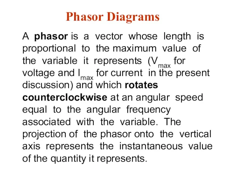
- 6. Phasor Diagrams A phasor is a vector whose length is proportional to the maximum value of
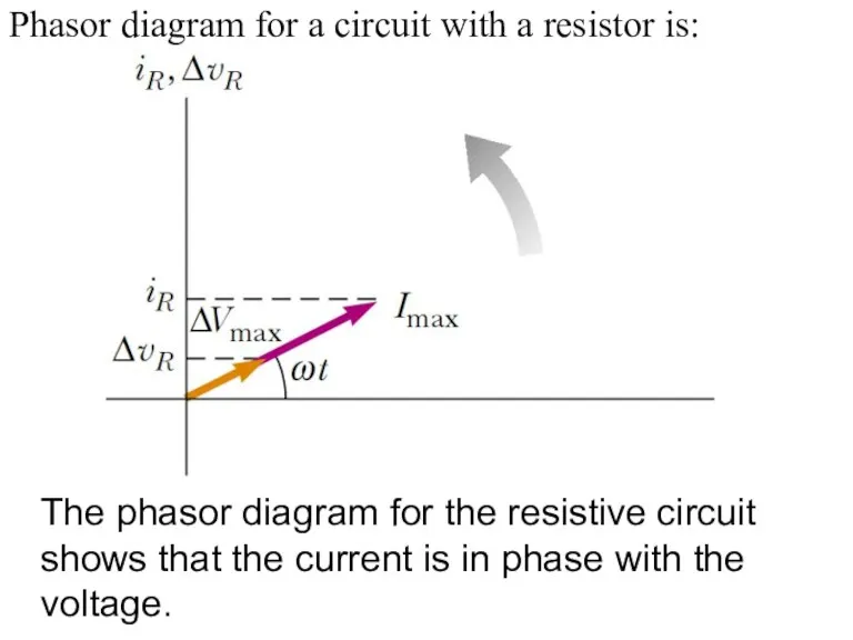
- 7. Phasor diagram for a circuit with a resistor is: The phasor diagram for the resistive circuit
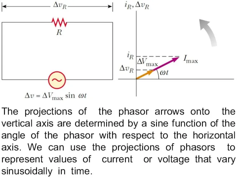
- 8. The projections of the phasor arrows onto the vertical axis are determined by a sine function
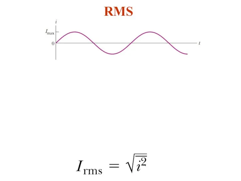
- 9. RMS
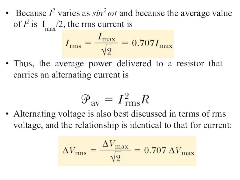
- 10. Because I2 varies as sin2 ωt and because the average value of I2 is Imax/2, the
- 11. One reason we use rms values when discussing alternating currents and voltages in this chapter is
- 12. Inductors in AC Circuits Kirchhoff’s rule for AC circuit with an inductor is: After derivation we
- 13. The maximal current in the inductor is We can define the inductive reactance as resistance of
- 14. Phasor diagram for the inductive circuit, showing that the current lags behind the voltage by 90°.
- 15. Capacitors in AC The current is π/2 rad = 90° out of phase with the voltage
- 16. The maximal current is: The capacitive reactance of the capacitor to the sinusoidal current is: Then
- 17. Plot of the instantaneous current iC and instantaneous voltage ΔVC across a capacitor as functions of
- 18. The RLC Series Circuit For convenience, and not losing generalization, we can assume that the applied
- 19. The voltage across each element has a different amplitude and phase:
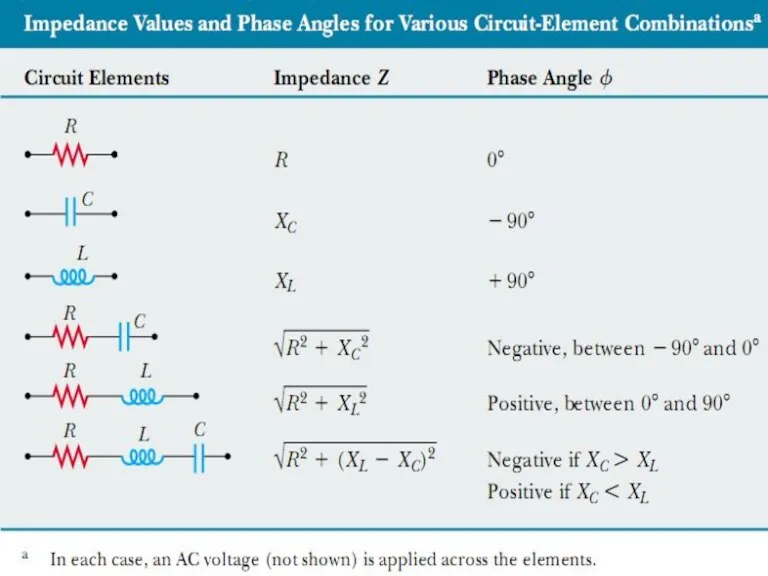
- 21. Impedance Using the previous calculations we can define a new parameter impedance: So, the amplitudes of
- 23. Power in AC Circuit The average power delivered by the source is converted to internal energy
- 24. Series RLC Circuit Resonance A series RLC circuit is in resonance when the current has its
- 25. The average power dissipating in the resistor is Then at resonance the average power is a
- 27. Скачать презентацию
Lecture 3
Alternating Current (AC)
Inductors in AC Circuits
Capacitors in AC Circuits
Series RLC
Lecture 3
Alternating Current (AC)
Inductors in AC Circuits
Capacitors in AC Circuits
Series RLC
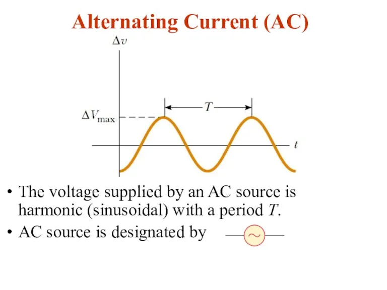
Alternating Current (AC)
The voltage supplied by an AC source is harmonic
Alternating Current (AC)
The voltage supplied by an AC source is harmonic
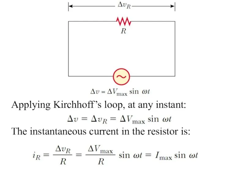
Applying Kirchhoff’s loop, at any instant:
The instantaneous current in the resistor
Applying Kirchhoff’s loop, at any instant:
The instantaneous current in the resistor
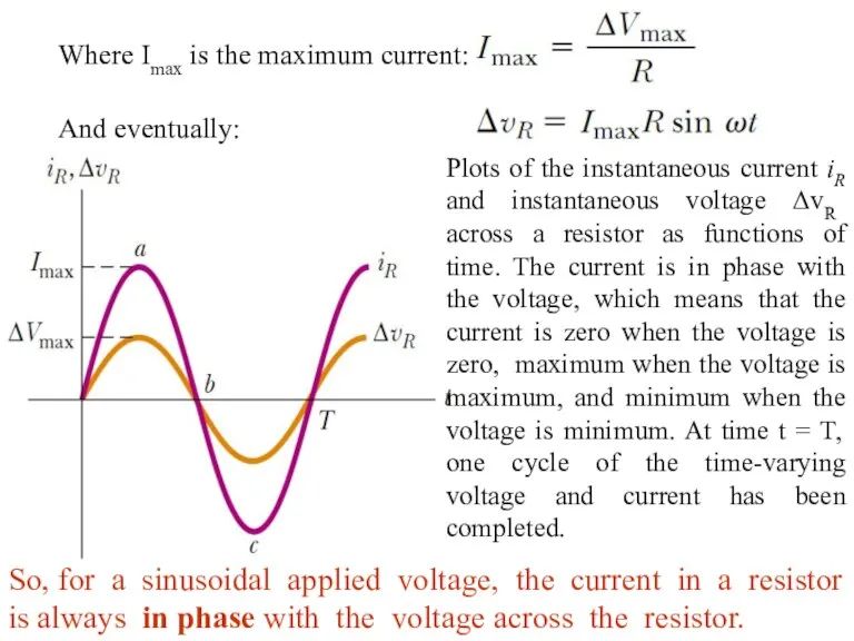
Where Imax is the maximum current:
And eventually:
Plots of the instantaneous current
And eventually:
Plots of the instantaneous current
Phasor Diagrams
A phasor is a vector whose length is proportional to
Phasor Diagrams
A phasor is a vector whose length is proportional to
Phasor diagram for a circuit with a resistor is:
The phasor diagram
Phasor diagram for a circuit with a resistor is:
The phasor diagram
The projections of the phasor arrows onto the vertical axis are
The projections of the phasor arrows onto the vertical axis are
RMS
RMS
Because I2 varies as sin2 ωt and because the average
Because I2 varies as sin2 ωt and because the average
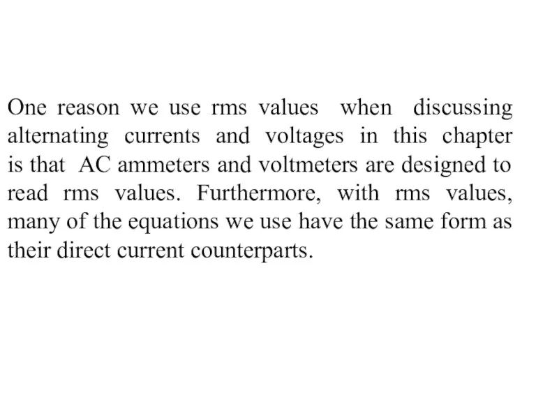
One reason we use rms values when discussing alternating currents and
One reason we use rms values when discussing alternating currents and
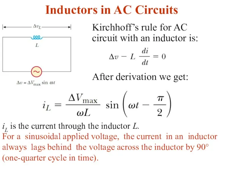
Inductors in AC Circuits
Kirchhoff’s rule for AC circuit with an inductor
Inductors in AC Circuits
Kirchhoff’s rule for AC circuit with an inductor
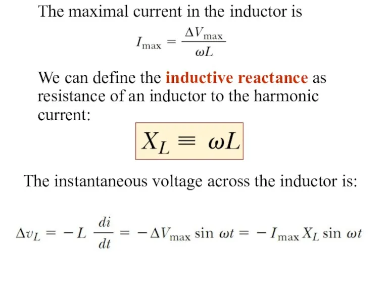
The maximal current in the inductor is
We can define the inductive
The maximal current in the inductor is
We can define the inductive
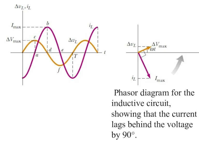
Phasor diagram for the inductive circuit, showing that the current
Phasor diagram for the inductive circuit, showing that the current
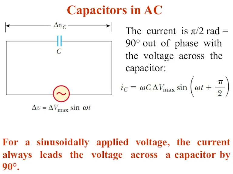
Capacitors in AC
The current is π/2 rad = 90° out of
Capacitors in AC
The current is π/2 rad = 90° out of
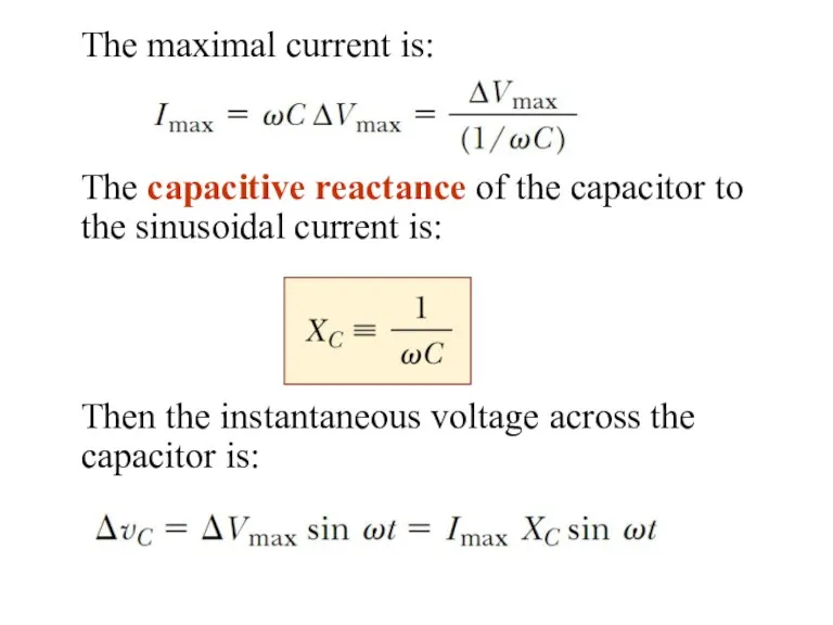
The maximal current is:
The capacitive reactance of the capacitor to the
The maximal current is:
The capacitive reactance of the capacitor to the
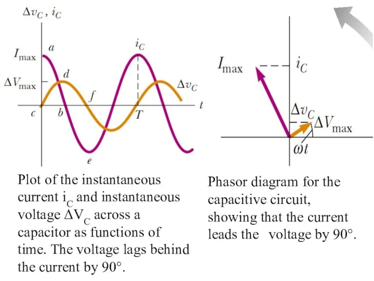
Plot of the instantaneous current iC and instantaneous voltage ΔVC across
Plot of the instantaneous current iC and instantaneous voltage ΔVC across
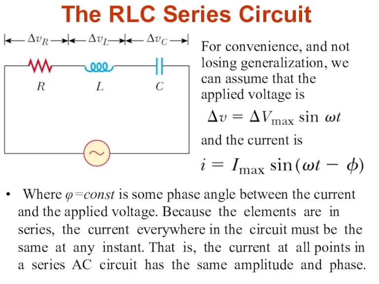
The RLC Series Circuit
For convenience, and not losing generalization, we can
The RLC Series Circuit
For convenience, and not losing generalization, we can
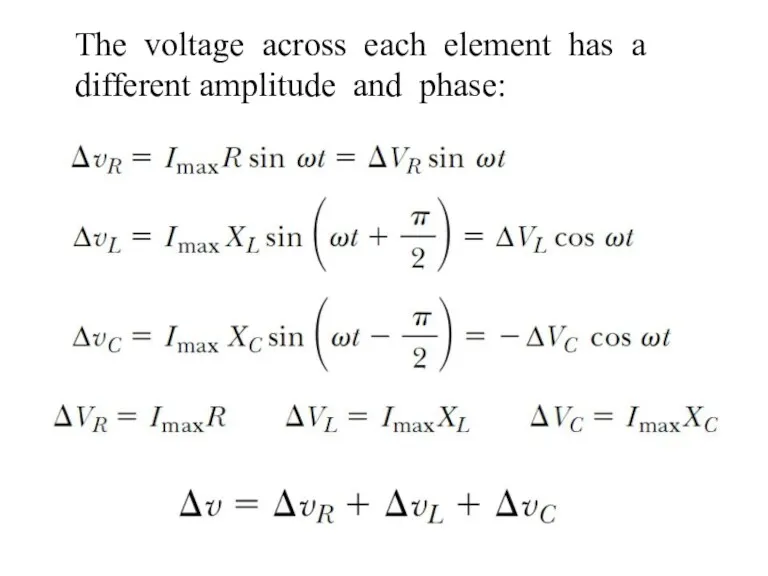
The voltage across each element has a different amplitude and phase:
The voltage across each element has a different amplitude and phase:
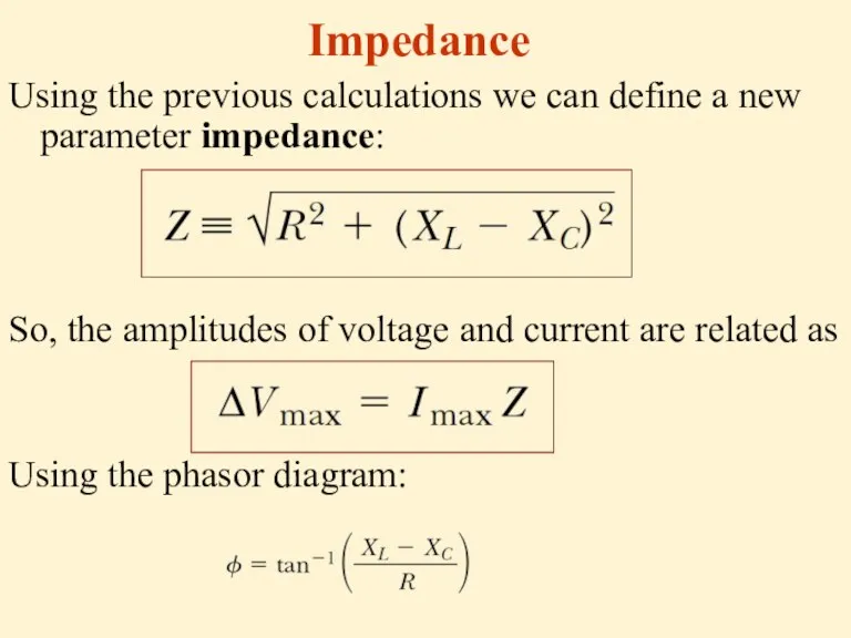
Impedance
Using the previous calculations we can define a new parameter impedance:
So,
Impedance
Using the previous calculations we can define a new parameter impedance:
So,
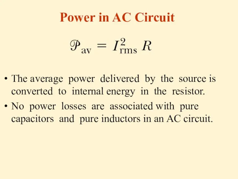
Power in AC Circuit
The average power delivered by the source is
Power in AC Circuit
The average power delivered by the source is
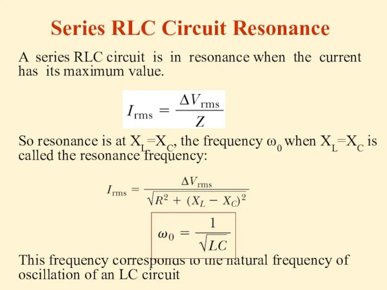
Series RLC Circuit Resonance
A series RLC circuit is in resonance when
Series RLC Circuit Resonance
A series RLC circuit is in resonance when
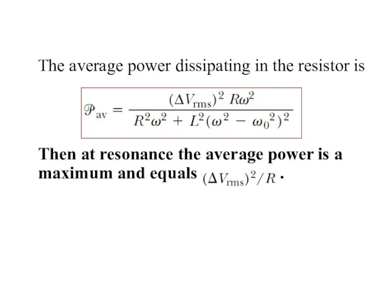
The average power dissipating in the resistor is
Then at resonance the
The average power dissipating in the resistor is
Then at resonance the
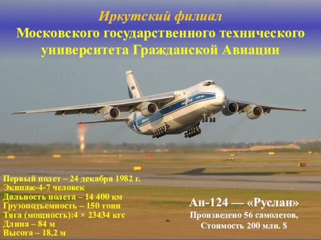 Самолёт Ан-124 Руслан. Взаимозаменяемость деталей самолетов. (Лекция 11)
 Основы термодинамики
 Измерение и оценка факторов: неионизирующие электромагнитные поля (ЭМП) и излучения
 Слесарные работы. Основное оборудование рабочего места и инструмент слесаря
 Колебания. Основные определения
 Ядерный реактор
 лабораторная работа №1 10 класс
 Электростатика
 Интерференция света
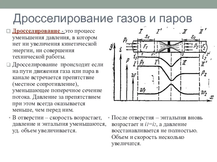 Дросселирование газов и паров
 Фізичні та хімічні явища
 Силы в механике: сила упругости, сила сухого и вязкого трения
 Судовые кислотные аккумуляторы
 Изучение электрической цепи.
 Лінійні електричні кола постійного струму
 Расчеты элементов конструкции на срез и смятие
 Полупроводники
 Определение коэффициента поверхностного натяжения синтетических моющих средств
 Строение атома. Ученые древности о строении вещества
 Пористость. Виды пористости
 Изучение последовательного и параллельного соединения проводников. Отчет о лабораторной работе №9
 Дисперсия света
 Лекция № 8. Тема: Физические механизмы переноса веществ через мембрану
 Физика в професії кухаря
 Тепловое излучение. Лекция 9
 Физическая игра Счастливый случай. 8 класс
 Формирование позитивного отношения к ядерной энергетике
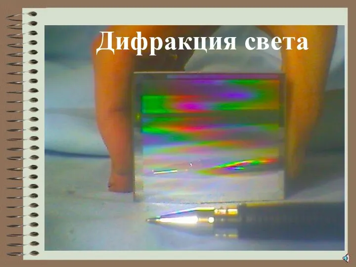 дз_ДИФРАКЦИЯ