- Axles and shafts

Содержание
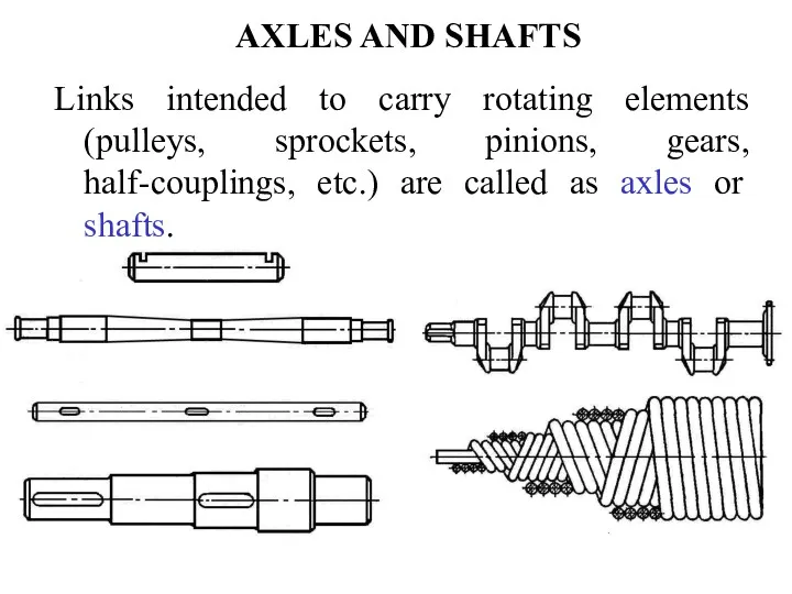
- 2. AXLES AND SHAFTS Links intended to carry rotating elements (pulleys, sprockets, pinions, gears, half-couplings, etc.) are
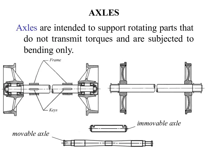
- 3. AXLES Axles are intended to support rotating parts that do not transmit torques and are subjected
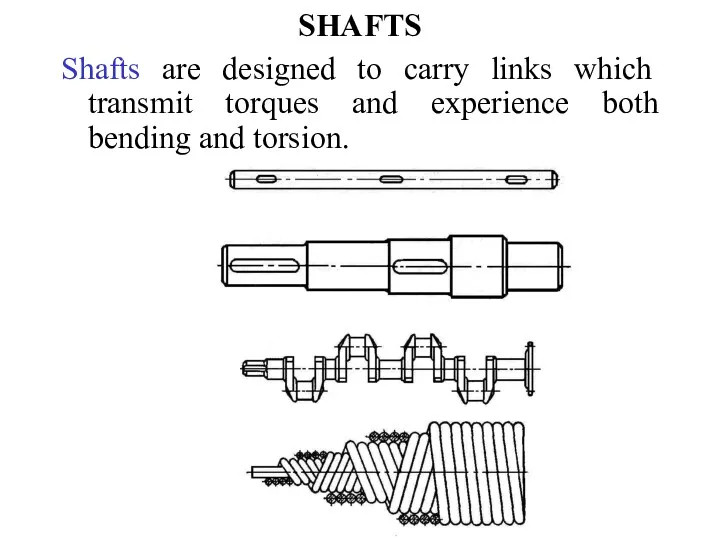
- 4. SHAFTS Shafts are designed to carry links which transmit torques and experience both bending and torsion.
- 5. CLASSIFICATION OF SHAFTS According to purpose Shafts of various drives (gear drives, belt drives, chain drives
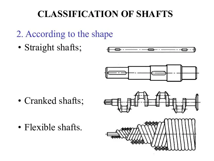
- 6. CLASSIFICATION OF SHAFTS 2. According to the shape Straight shafts; Cranked shafts; Flexible shafts.
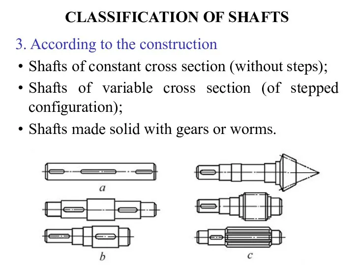
- 7. CLASSIFICATION OF SHAFTS 3. According to the construction Shafts of constant cross section (without steps); Shafts
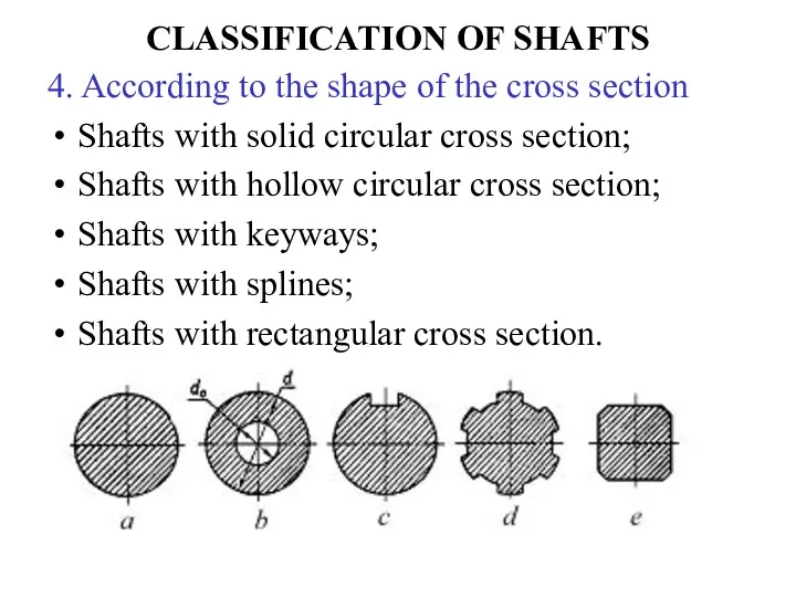
- 8. CLASSIFICATION OF SHAFTS 4. According to the shape of the cross section Shafts with solid circular
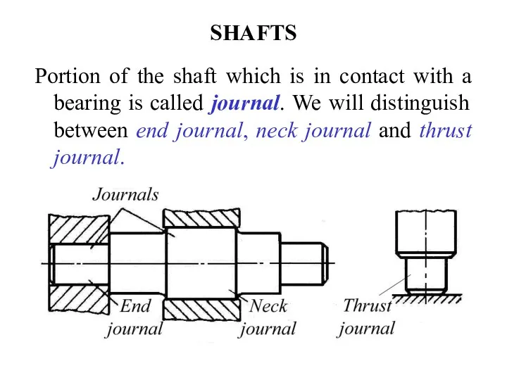
- 9. SHAFTS Portion of the shaft which is in contact with a bearing is called journal. We
- 10. CALCULATION OF SHAFTS Strength; Rigidity; Oscillations. Shafts may be calculated for:
- 11. CALCULATION OF SHAFTS FOR STRENGTH Determination of the minimum diameter of the shaft; Designing the shaft
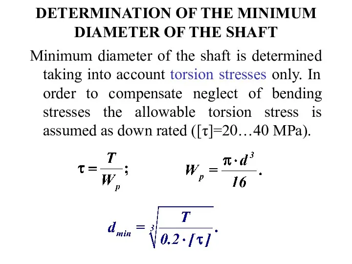
- 12. DETERMINATION OF THE MINIMUM DIAMETER OF THE SHAFT Minimum diameter of the shaft is determined taking
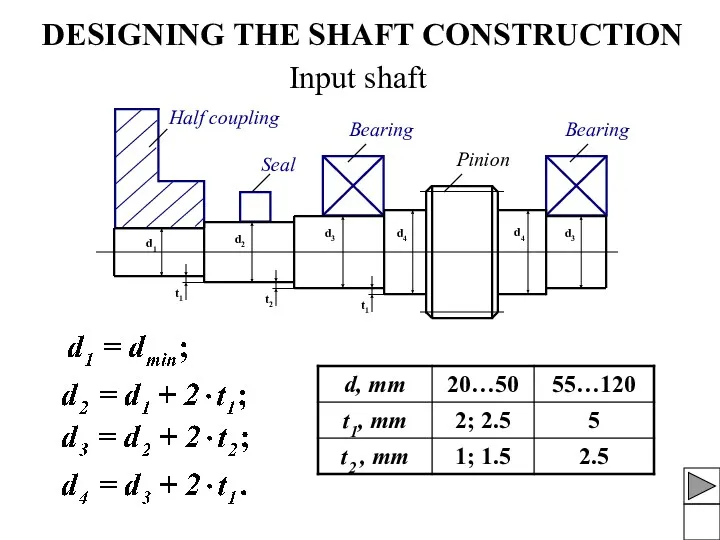
- 13. DESIGNING THE SHAFT CONSTRUCTION Input shaft Half coupling Seal Bearing Bearing Pinion
- 14. SEALS Seals are divided into: Commercial seals (Lip-type seals); Labyrinth seals; Groove seals; Combined seals. Rubbing
- 15. DESIGNING THE SHAFT CONSTRUCTION Input bevel pinion shaft Input worm shaft
- 16. DESIGNING THE SHAFT CONSTRUCTION Intermediate shaft d1 d2 d2 d1 Bearing Bearing Pinion d3 Gear
- 17. DESIGNING THE SHAFT CONSTRUCTION Output shaft Bearing
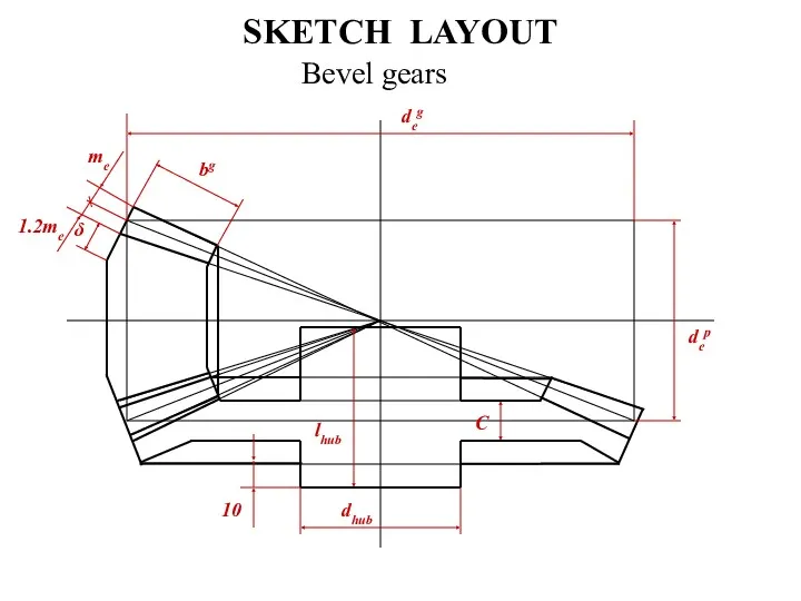
- 18. SPUR GEAR Thickness of the rim δ = (3…4)·m; Thickness of the web C = (0.2…0.3)·bg;
- 19. WORM GEAR Thickness of the bronze ring δ1= 2·m; Thickness of the steel rim δ2= 2·m;
- 20. SKETCH LAYOUT Double stage spur gear speed reducer I I
- 21. SKETCH LAYOUT Double stage coaxial spur gear speed reducer
- 22. SKETCH LAYOUT Bevel gears
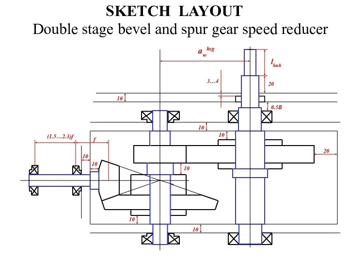
- 23. SKETCH LAYOUT Double stage bevel and spur gear speed reducer
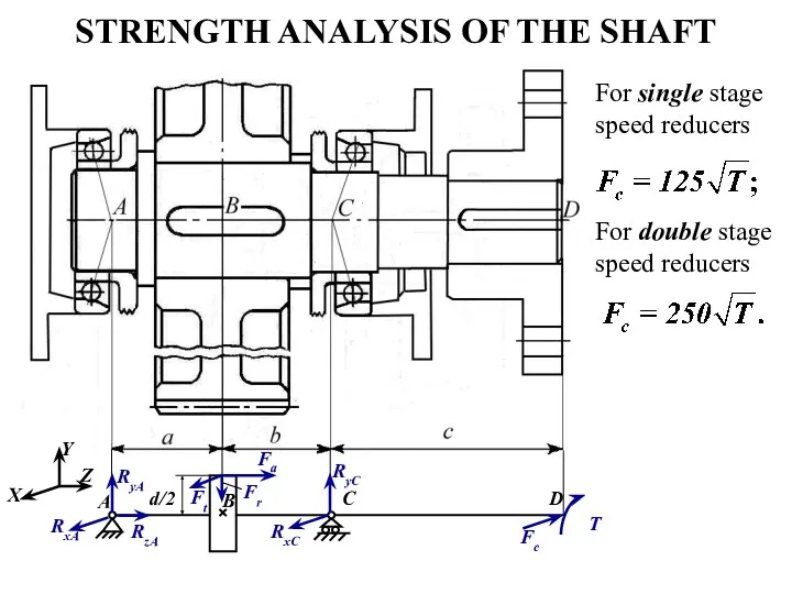
- 24. STRENGTH ANALYSIS OF THE SHAFT For single stage speed reducers For double stage speed reducers
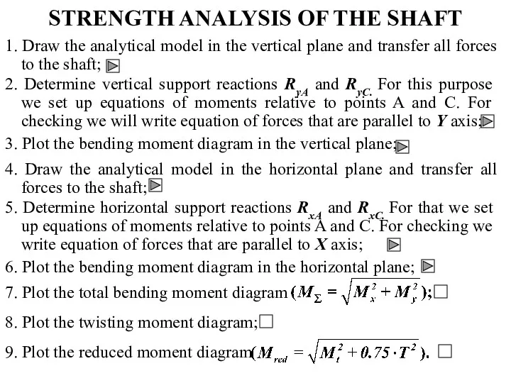
- 25. STRENGTH ANALYSIS OF THE SHAFT 1. Draw the analytical model in the vertical plane and transfer
- 26. STRENGTH ANALYSIS OF THE SHAFT Checking: 1. 2. 3. 5. Checking: 6. 4.
- 27. STRENGTH ANALYSIS OF THE SHAFT T 7. 8. 9. Calculation for static strength Mred max is
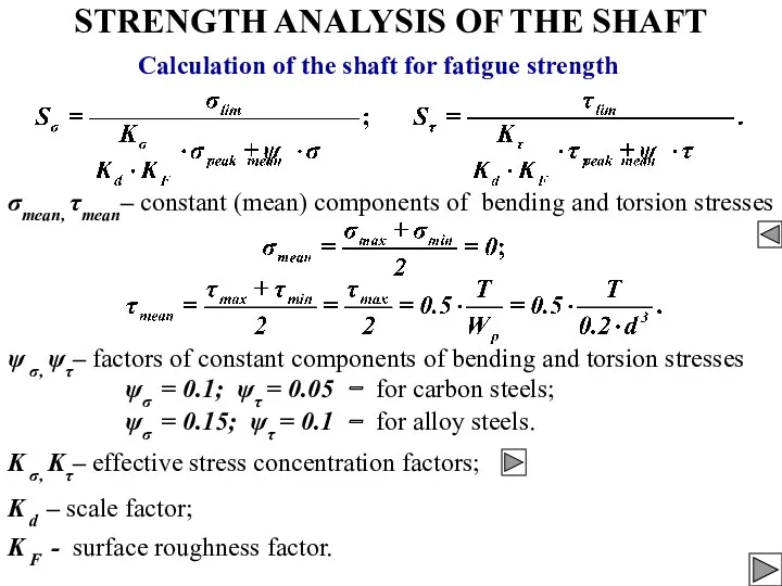
- 28. STRENGTH ANALYSIS OF THE SHAFT Calculation of the shaft for fatigue strength Changing of bending stresses
- 29. STRENGTH ANALYSIS OF THE SHAFT Calculation of the shaft for fatigue strength σlim, τlim – limit
- 30. STRENGTH ANALYSIS OF THE SHAFT ψσ = 0.1; ψτ = 0.05 − for carbon steels; ψσ
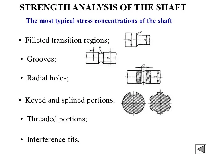
- 31. STRENGTH ANALYSIS OF THE SHAFT The most typical stress concentrations of the shaft Filleted transition regions;
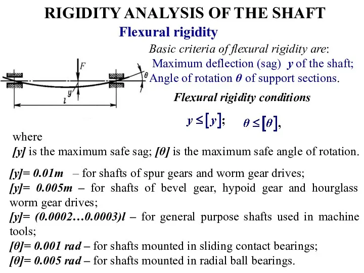
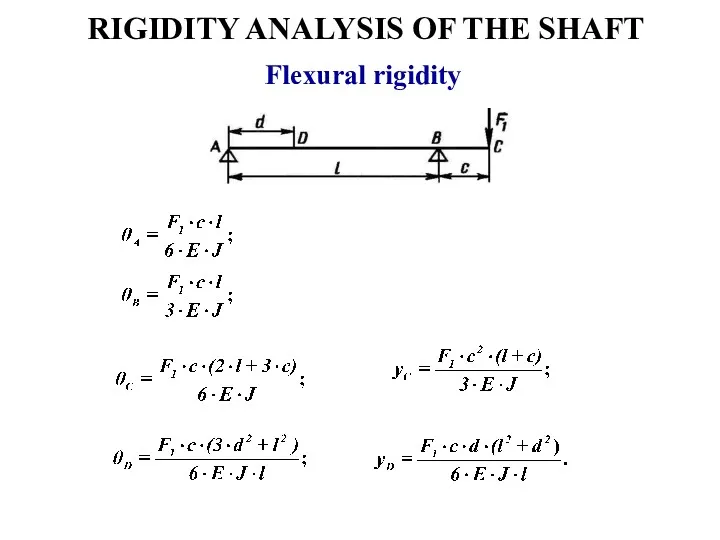
- 32. RIGIDITY ANALYSIS OF THE SHAFT Flexural rigidity Basic criteria of flexural rigidity are: Maximum deflection (sag)
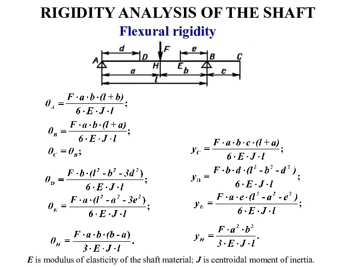
- 33. RIGIDITY ANALYSIS OF THE SHAFT Flexural rigidity E is modulus of elasticity of the shaft material;
- 34. RIGIDITY ANALYSIS OF THE SHAFT Flexural rigidity
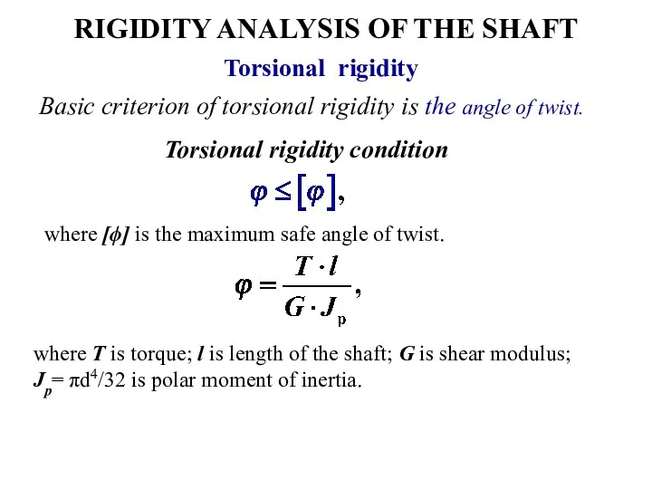
- 35. RIGIDITY ANALYSIS OF THE SHAFT Basic criterion of torsional rigidity is the angle of twist. Torsional
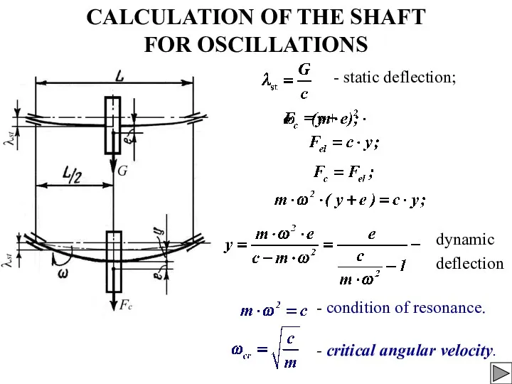
- 36. CALCULATION OF THE SHAFT FOR OSCILLATIONS - static deflection; dynamic deflection - condition of resonance. -
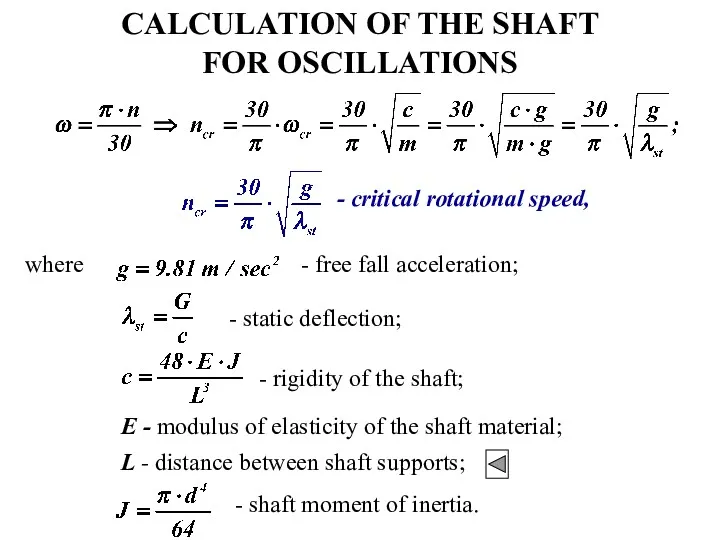
- 37. CALCULATION OF THE SHAFT FOR OSCILLATIONS - critical rotational speed, where - free fall acceleration; -
- 39. Скачать презентацию
AXLES AND SHAFTS
Links intended to carry rotating elements (pulleys, sprockets, pinions,
AXLES AND SHAFTS
Links intended to carry rotating elements (pulleys, sprockets, pinions,
AXLES
Axles are intended to support rotating parts that do not transmit
AXLES
Axles are intended to support rotating parts that do not transmit
SHAFTS
Shafts are designed to carry links which transmit torques and experience
SHAFTS
Shafts are designed to carry links which transmit torques and experience
CLASSIFICATION OF SHAFTS
According to purpose
Shafts of various drives (gear drives, belt
CLASSIFICATION OF SHAFTS
According to purpose
Shafts of various drives (gear drives, belt
CLASSIFICATION OF SHAFTS
2. According to the shape
Straight shafts;
Cranked shafts;
Flexible shafts.
CLASSIFICATION OF SHAFTS
2. According to the shape
Straight shafts;
Cranked shafts;
Flexible shafts.
CLASSIFICATION OF SHAFTS
3. According to the construction
Shafts of constant cross section
CLASSIFICATION OF SHAFTS
3. According to the construction
Shafts of constant cross section
CLASSIFICATION OF SHAFTS
4. According to the shape of the cross section
Shafts
CLASSIFICATION OF SHAFTS
4. According to the shape of the cross section
Shafts
SHAFTS
Portion of the shaft which is in contact with a bearing
SHAFTS
Portion of the shaft which is in contact with a bearing
CALCULATION OF SHAFTS
Strength;
Rigidity;
Oscillations.
Shafts may be calculated for:
CALCULATION OF SHAFTS
Strength;
Rigidity;
Oscillations.
Shafts may be calculated for:
CALCULATION OF SHAFTS
FOR STRENGTH
Determination of the minimum diameter of the
CALCULATION OF SHAFTS
FOR STRENGTH
Determination of the minimum diameter of the
DETERMINATION OF THE MINIMUM DIAMETER OF THE SHAFT
Minimum diameter of the
DETERMINATION OF THE MINIMUM DIAMETER OF THE SHAFT
Minimum diameter of the
DESIGNING THE SHAFT CONSTRUCTION
Input shaft
Half coupling
Seal
Bearing
Bearing
Pinion
DESIGNING THE SHAFT CONSTRUCTION
Input shaft
Half coupling
Seal
Bearing
Bearing
Pinion
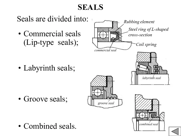
SEALS
Seals are divided into:
Commercial seals (Lip-type seals);
Labyrinth seals;
Groove seals;
Combined seals.
Rubbing element
Steel
SEALS
Seals are divided into:
Commercial seals (Lip-type seals);
Labyrinth seals;
Groove seals;
Combined seals.
Rubbing element
Steel
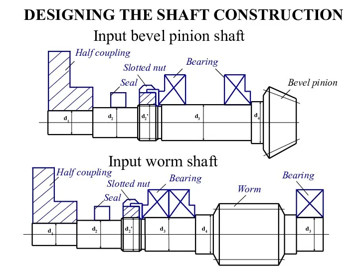
DESIGNING THE SHAFT CONSTRUCTION
Input bevel pinion shaft
Input worm shaft
DESIGNING THE SHAFT CONSTRUCTION
Input bevel pinion shaft
Input worm shaft
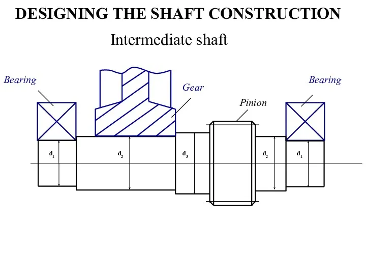
DESIGNING THE SHAFT CONSTRUCTION
Intermediate shaft
d1
d2
d2
d1
Bearing
Bearing
Pinion
d3
Gear
DESIGNING THE SHAFT CONSTRUCTION
Intermediate shaft
d1
d2
d2
d1
Bearing
Bearing
Pinion
d3
Gear
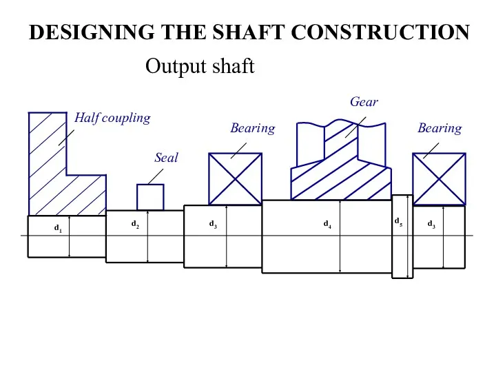
DESIGNING THE SHAFT CONSTRUCTION
Output shaft
Bearing
DESIGNING THE SHAFT CONSTRUCTION
Output shaft
Bearing
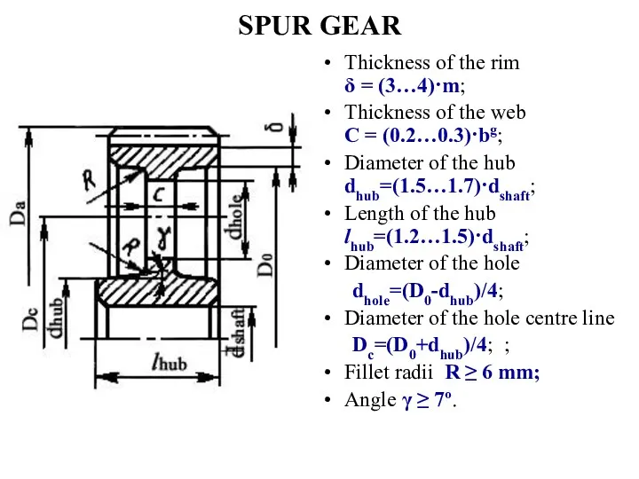
SPUR GEAR
Thickness of the rim δ = (3…4)·m;
Thickness of the web
SPUR GEAR
Thickness of the rim δ = (3…4)·m;
Thickness of the web
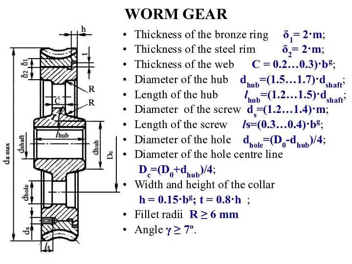
WORM GEAR
Thickness of the bronze ring δ1= 2·m;
Thickness of the steel
WORM GEAR
Thickness of the bronze ring δ1= 2·m;
Thickness of the steel
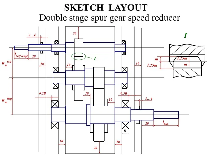
SKETCH LAYOUT
Double stage spur gear speed reducer
I
I
SKETCH LAYOUT
Double stage spur gear speed reducer
I
I
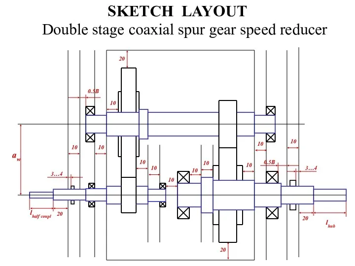
SKETCH LAYOUT
Double stage coaxial spur gear speed reducer
SKETCH LAYOUT
Double stage coaxial spur gear speed reducer
SKETCH LAYOUT
Bevel gears
SKETCH LAYOUT
Bevel gears
SKETCH LAYOUT
Double stage bevel and spur gear speed reducer
SKETCH LAYOUT
Double stage bevel and spur gear speed reducer
STRENGTH ANALYSIS OF THE SHAFT
For single stage
speed reducers
For double stage
STRENGTH ANALYSIS OF THE SHAFT
For single stage
speed reducers
For double stage
STRENGTH ANALYSIS OF THE SHAFT
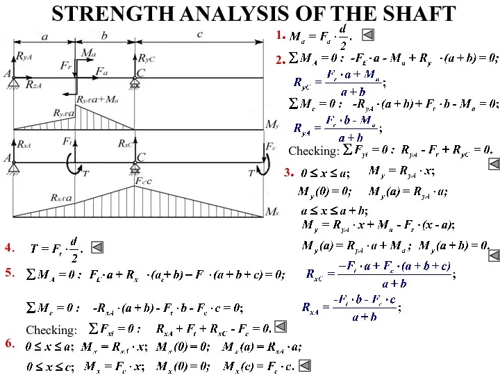
1. Draw the analytical model in the
STRENGTH ANALYSIS OF THE SHAFT
1. Draw the analytical model in the
STRENGTH ANALYSIS OF THE SHAFT
Checking:
1.
2.
3.
5.
Checking:
6.
4.
STRENGTH ANALYSIS OF THE SHAFT
Checking:
1.
2.
3.
5.
Checking:
6.
4.
STRENGTH ANALYSIS OF THE SHAFT
T
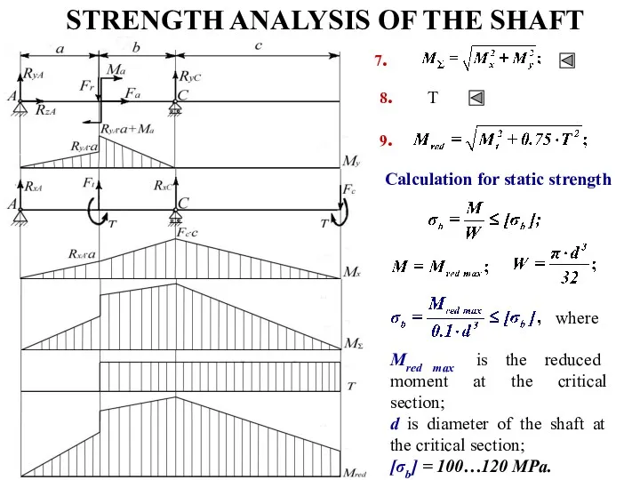
7.
8.
9.
Calculation for static strength
Mred max is the
STRENGTH ANALYSIS OF THE SHAFT
T
7.
8.
9.
Calculation for static strength
Mred max is the
STRENGTH ANALYSIS OF THE SHAFT
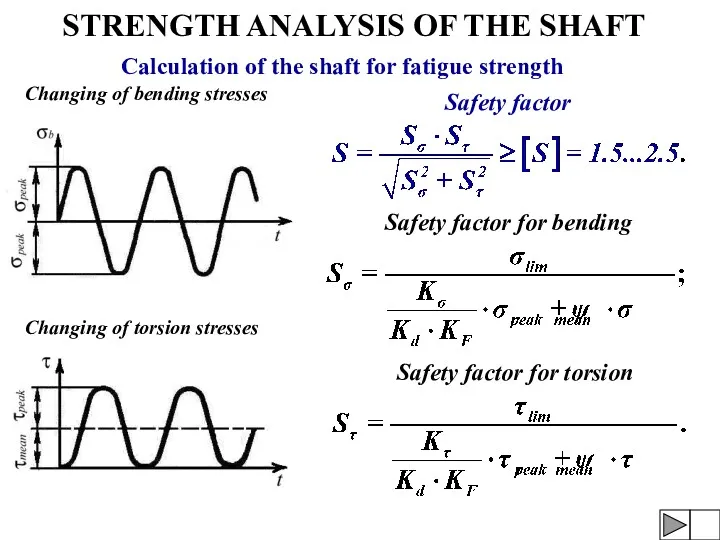
Calculation of the shaft for fatigue strength
Changing
STRENGTH ANALYSIS OF THE SHAFT
Calculation of the shaft for fatigue strength
Changing
STRENGTH ANALYSIS OF THE SHAFT
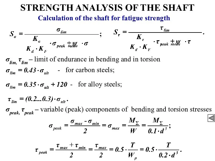
Calculation of the shaft for fatigue strength
σlim,
STRENGTH ANALYSIS OF THE SHAFT
Calculation of the shaft for fatigue strength
σlim,
STRENGTH ANALYSIS OF THE SHAFT
ψσ = 0.1; ψτ = 0.05 −
STRENGTH ANALYSIS OF THE SHAFT
ψσ = 0.1; ψτ = 0.05 −
STRENGTH ANALYSIS OF THE SHAFT
The most typical stress concentrations of the
STRENGTH ANALYSIS OF THE SHAFT
The most typical stress concentrations of the
RIGIDITY ANALYSIS OF THE SHAFT
Flexural rigidity
Basic criteria of flexural rigidity are:
RIGIDITY ANALYSIS OF THE SHAFT
Flexural rigidity
Basic criteria of flexural rigidity are:
RIGIDITY ANALYSIS OF THE SHAFT
Flexural rigidity
E is modulus of elasticity of
RIGIDITY ANALYSIS OF THE SHAFT
Flexural rigidity
E is modulus of elasticity of
RIGIDITY ANALYSIS OF THE SHAFT
Flexural rigidity
RIGIDITY ANALYSIS OF THE SHAFT
Flexural rigidity
RIGIDITY ANALYSIS OF THE SHAFT
Basic criterion of torsional rigidity is the
RIGIDITY ANALYSIS OF THE SHAFT
Basic criterion of torsional rigidity is the
CALCULATION OF THE SHAFT
FOR OSCILLATIONS
- static deflection;
dynamic
deflection
- condition of
CALCULATION OF THE SHAFT
FOR OSCILLATIONS
- static deflection;
dynamic
deflection
- condition of
CALCULATION OF THE SHAFT
FOR OSCILLATIONS
- critical rotational speed,
where
- free fall
CALCULATION OF THE SHAFT
FOR OSCILLATIONS
- critical rotational speed,
where
- free fall
 Истечение из отверстий и насадок
 Законы постоянного тока Тема урока: Электрический ток. Сила тока.
 Способы соединения жил кабелей
 Квантовая физика. Фотоэффект
 Схематизация опор. Определение реакций
 Изготовление столярного соединения УС-1
 Проводники в электрическом поле. Диэлектрики в электрическом поле
 Механические колебания. 11 класс
 Магнит өрісіндегі тогы бар контур
 Кванттық теорияның бастаулары
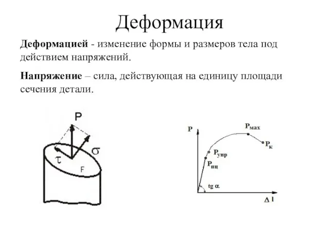 Деформация. Механизмы пластической деформации
 Химические источники тока гальванические элементы, аккумуляторы
 Квантовые постулаты Бора
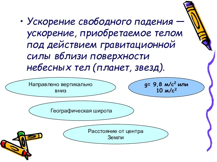 Ускорение свободного падения
 Элементы релятивистской механики. Специальная теория относительности. (Лекция 4.2)
 Зависимость давления насыщенного пара от температуры. Кипение
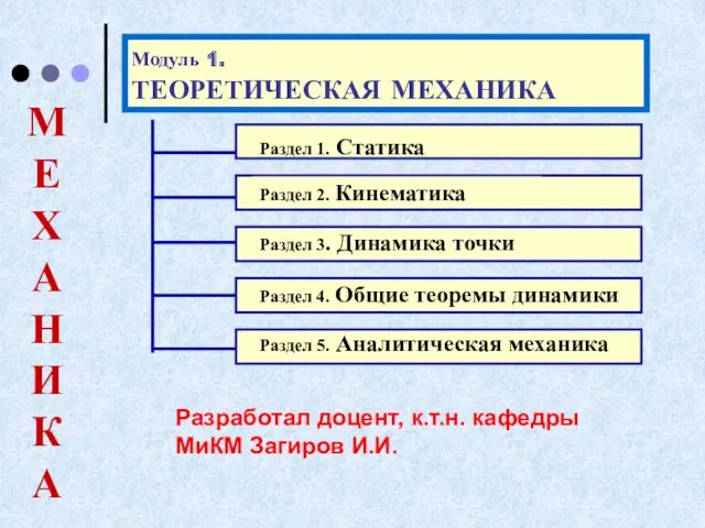 ЛЕКЦИИ термех. модуль 1
 Презентация по теме: Газовые законы
 Механические волны
 Презентация по физике для 8 класса - своя игра по теме Электричество
 Зачем физика повару?
 Использование электронных образовательных ресурсов в преподавании физики
 Плавление и отвердевание кристаллических тел
 Преломление и полное внутреннее отражение света
 Простые механизмы. Зубчатая передача
 электродинамика 11 класс
 презентация Введение в предмет
 Основы теории напряженного состояния. Лекция 9