Слайд 2
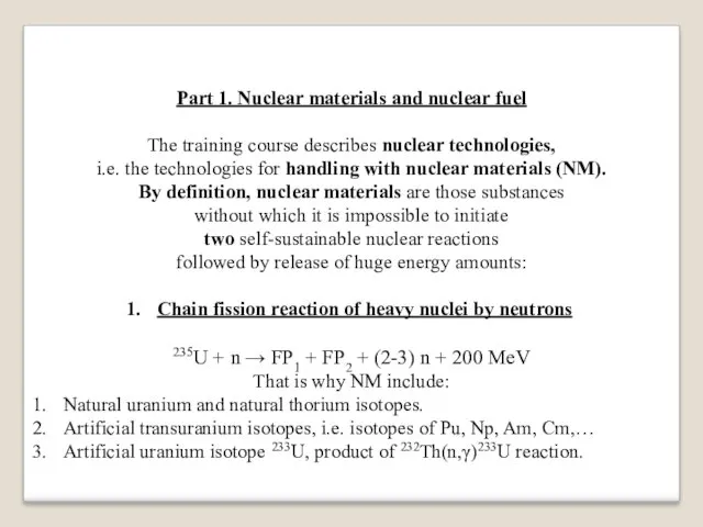
Part 1. Nuclear materials and nuclear fuel
The training course describes nuclear
technologies,
i.e. the technologies for handling with nuclear materials (NM).
By definition, nuclear materials are those substances
without which it is impossible to initiate
two self-sustainable nuclear reactions
followed by release of huge energy amounts:
Chain fission reaction of heavy nuclei by neutrons
235U + n → FP1 + FP2 + (2-3) n + 200 MeV
That is why NM include:
Natural uranium and natural thorium isotopes.
Artificial transuranium isotopes, i.e. isotopes of Pu, Np, Am, Cm,…
Artificial uranium isotope 233U, product of 232Th(n,γ)233U reaction.
Слайд 3
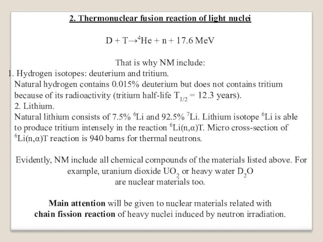
2. Thermonuclear fusion reaction of light nuclei
D + T→4He + n
+ 17.6 MeV
That is why NM include:
Hydrogen isotopes: deuterium and tritium.
Natural hydrogen contains 0.015% deuterium but does not contains tritium because of its radioactivity (tritium half-life Т1/2 = 12.3 years).
2. Lithium.
Natural lithium consists of 7.5% 6Li and 92.5% 7Li. Lithium isotope 6Li is able to produce tritium intensely in the reaction 6Li(n,α)T. Micro cross-section of 6Li(n,α)T reaction is 940 barns for thermal neutrons.
Evidently, NM include all chemical compounds of the materials listed above. For example, uranium dioxide UO2 or heavy water D2O
are nuclear materials too.
Main attention will be given to nuclear materials related with
chain fission reaction of heavy nuclei induced by neutron irradiation.
Слайд 4
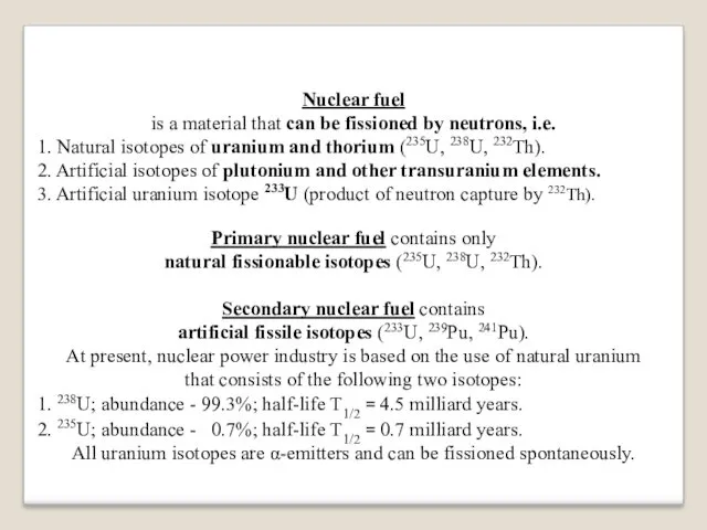
Nuclear fuel
is a material that can be fissioned by neutrons, i.e.
1.
Natural isotopes of uranium and thorium (235U, 238U, 232Th).
2. Artificial isotopes of plutonium and other transuranium elements.
3. Artificial uranium isotope 233U (product of neutron capture by 232Th).
Primary nuclear fuel contains only
natural fissionable isotopes (235U, 238U, 232Th).
Secondary nuclear fuel contains
artificial fissile isotopes (233U, 239Pu, 241Pu).
At present, nuclear power industry is based on the use of natural uranium
that consists of the following two isotopes:
1. 238U; abundance - 99.3%; half-life Т1/2 = 4.5 milliard years.
2. 235U; abundance - 0.7%; half-life Т1/2 = 0.7 milliard years.
All uranium isotopes are α-emitters and can be fissioned spontaneously.
Слайд 5
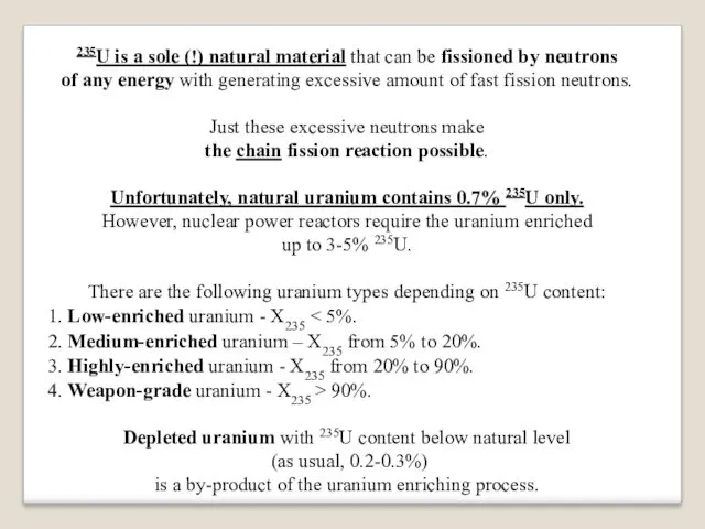
235U is a sole (!) natural material that can be fissioned
by neutrons
of any energy with generating excessive amount of fast fission neutrons.
Just these excessive neutrons make
the chain fission reaction possible.
Unfortunately, natural uranium contains 0.7% 235U only.
However, nuclear power reactors require the uranium enriched
up to 3-5% 235U.
There are the following uranium types depending on 235U content:
1. Low-enriched uranium - X235 < 5%.
2. Medium-enriched uranium – X235 from 5% to 20%.
3. Highly-enriched uranium - X235 from 20% to 90%.
4. Weapon-grade uranium - X235 > 90%.
Depleted uranium with 235U content below natural level
(as usual, 0.2-0.3%)
is a by-product of the uranium enriching process.
Слайд 6
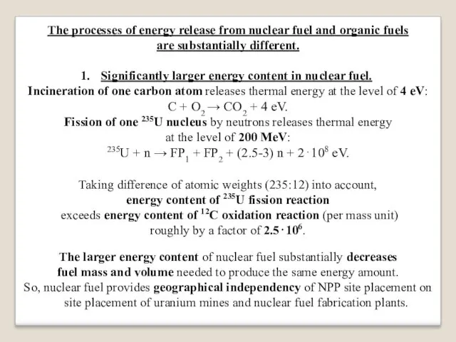
The processes of energy release from nuclear fuel and organic fuels
are
substantially different.
Significantly larger energy content in nuclear fuel.
Incineration of one carbon atom releases thermal energy at the level of 4 eV:
C + O2 → CO2 + 4 eV.
Fission of one 235U nucleus by neutrons releases thermal energy
at the level of 200 MeV:
235U + n → FP1 + FP2 + (2.5-3) n + 2⋅108 eV.
Taking difference of atomic weights (235:12) into account,
energy content of 235U fission reaction
exceeds energy content of 12C oxidation reaction (per mass unit)
roughly by a factor of 2.5⋅106.
The larger energy content of nuclear fuel substantially decreases
fuel mass and volume needed to produce the same energy amount.
So, nuclear fuel provides geographical independency of NPP site placement on site placement of uranium mines and nuclear fuel fabrication plants.
Слайд 7
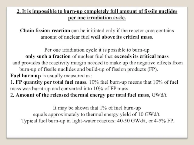
2. It is impossible to burn-up completely full amount of fissile
nuclides
per one irradiation cycle.
Chain fission reaction can be initiated only if the reactor core contains
amount of nuclear fuel well above its critical mass.
Per one irradiation cycle it is possible to burn-up
only such a fraction of nuclear fuel that exceeds its critical mass
and provides the reactivity margin needed to make up the negative effects from burn-up of fissile nuclides and build-up of fission products (FP).
Fuel burn-up is usually measured as:
1. FP quantity per total fuel mass. 10% fuel burn-up means that 10% of fuel mass was burnt-up and converted into 10% of FP mass.
2. Amount of the released thermal energy per total fuel mass, GWd/t.
It may be shown that 1% of fuel burn-up
equals approximately to thermal energy yield of 10 GWd/t.
Typical fuel burn-up in light-water reactors: 40-50 GWd/t, or 4-5% FP.
Слайд 8
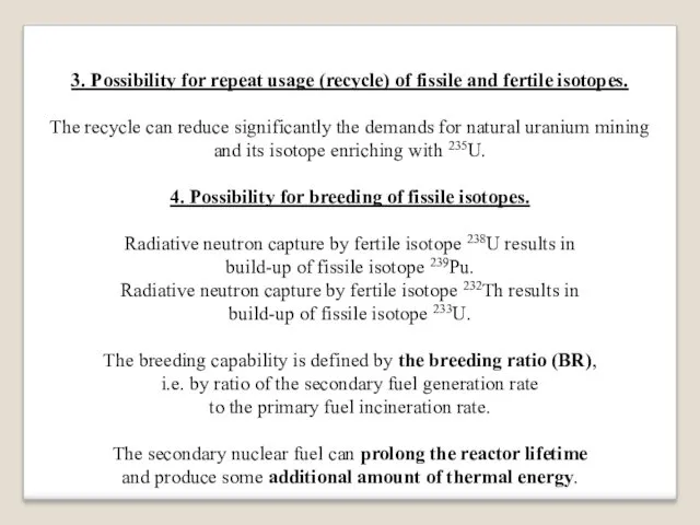
3. Possibility for repeat usage (recycle) of fissile and fertile isotopes.
The
recycle can reduce significantly the demands for natural uranium mining
and its isotope enriching with 235U.
4. Possibility for breeding of fissile isotopes.
Radiative neutron capture by fertile isotope 238U results in
build-up of fissile isotope 239Pu.
Radiative neutron capture by fertile isotope 232Th results in
build-up of fissile isotope 233U.
The breeding capability is defined by the breeding ratio (BR),
i.e. by ratio of the secondary fuel generation rate
to the primary fuel incineration rate.
The secondary nuclear fuel can prolong the reactor lifetime
and produce some additional amount of thermal energy.
Слайд 9
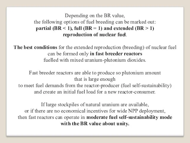
Depending on the BR value,
the following options of fuel breeding can
be marked out:
partial (BR < 1), full (BR = 1) and extended (BR > 1)
reproduction of nuclear fuel.
The best conditions for the extended reproduction (breeding) of nuclear fuel
can be formed only in fast breeder reactors
fuelled with mixed uranium-plutonium dioxides.
Fast breeder reactors are able to produce so plutonium amount
that is large enough
to meet fuel demands from the reactor-producer (fuel self-sustainability)
and create an initial fuel load for a new reactor-consumer.
If large stockpiles of natural uranium are available,
or if there are no economical incentives for wide NPP deployment,
then fast reactors can operate in moderate fuel self-sustainability mode
with the BR value about unity.
Слайд 10
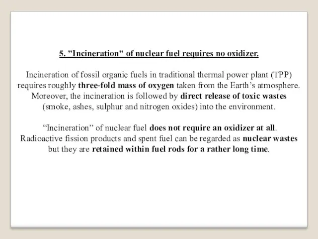
5. ”Incineration” of nuclear fuel requires no oxidizer.
Incineration of fossil organic
fuels in traditional thermal power plant (TPP) requires roughly three-fold mass of oxygen taken from the Earth’s atmosphere.
Moreover, the incineration is followed by direct release of toxic wastes
(smoke, ashes, sulphur and nitrogen oxides) into the environment.
“Incineration” of nuclear fuel does not require an oxidizer at all.
Radioactive fission products and spent fuel can be regarded as nuclear wastes but they are retained within fuel rods for a rather long time.
Слайд 11
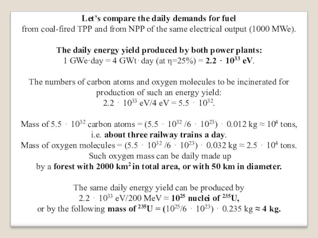
Let’s compare the daily demands for fuel
from coal-fired TPP and from
NPP of the same electrical output (1000 MWe).
The daily energy yield produced by both power plants:
1 GWe·day = 4 GWt⋅day (at η=25%) = 2.2 ⋅ 1033 eV.
The numbers of carbon atoms and oxygen molecules to be incinerated for production of such an energy yield:
2.2 ⋅ 1033 eV/4 eV = 5.5 ⋅ 1032.
Mass of 5.5 ⋅ 1032 carbon atoms = (5.5 ⋅ 1032 /6 ⋅ 1023) ⋅ 0.012 kg ≈ 104 tons,
i.e. about three railway trains a day.
Mass of oxygen molecules = (5.5 ⋅ 1032 /6 ⋅ 1023) ⋅ 0.032 kg ≈ 2.5 ⋅ 104 tons.
Such oxygen mass can be daily made up
by a forest with 2000 km2 in total area, or with 50 km in diameter.
The same daily energy yield can be produced by
2.2 ⋅ 1033 eV/200 MeV ≈ 1025 nuclei of 235U,
or by the following mass of 235U = (1025/6 ⋅ 1023) ⋅ 0.235 kg ≈ 4 kg.
Слайд 12
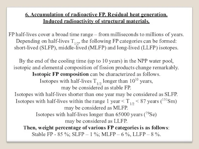
6. Accumulation of radioactive FP. Residual heat generation.
Induced radioactivity of structural
materials.
FP half-lives cover a broad time range – from milliseconds to millions of years.
Depending on half-lives T1/2, the following FP categories can be formed:
short-lived (SLFP), middle-lived (MLFP) and long-lived (LLFP) isotopes.
By the end of the cooling time (up to 10 years) in the NPP water pool,
isotopic and elemental composition of fission products change remarkably.
Isotopic FP composition can be characterized as follows.
Isotopes with half-lives Т1/2 longer than 1010 years,
may be considered as stable FP.
Isotopes with half-lives shorter than one year may be considered as SLFP.
Isotopes with half-lives within the range 1 year < Т1/2 < 87 years (151Sm)
may be considered as MLFP.
Isotopes with half-lives longer than 65000 years (79Se)
may be considered as LLFP.
Then, weight percentage of various FP categories is as follows:
Stable FP - 85 %; SLFP – 1 %; MLFP – 6 %, LLFP – 8 %.
Слайд 13
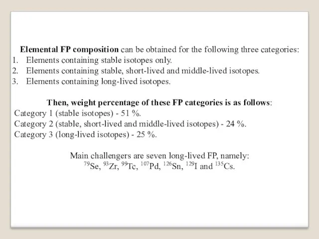
Elemental FP composition can be obtained for the following three categories:
Elements
containing stable isotopes only.
Elements containing stable, short-lived and middle-lived isotopes.
Elements containing long-lived isotopes.
Then, weight percentage of these FP categories is as follows:
Category 1 (stable isotopes) - 51 %.
Category 2 (stable, short-lived and middle-lived isotopes) - 24 %.
Category 3 (long-lived isotopes) - 25 %.
Main challengers are seven long-lived FP, namely:
79Se, 93Zr, 99Tc, 107Pd, 126Sn, 129I and 135Cs.
Слайд 14
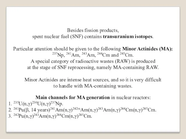
Besides fission products,
spent nuclear fuel (SNF) contains transuranium isotopes.
Particular attention
should be given to the following Minor Actinides (MA):
237Np, 241Am, 243Am, 244Cm and 245Cm.
A special category of radioactive wastes (RAW) is produced
at the stage of SNF reprocessing, namely MA-containing RAW.
Minor Actinides are intense heat sources, and so it is very difficult
to handle with MA-containing wastes.
Main channels for MA generation in nuclear reactors:
1. 235U(n,γ)236U(n,γ)237Np.
2. 241Pu(β, 14 years)241Am(n,γ)242mAm(n,γ)243Am(n,γ)244Cm(n,γ)245Cm.
3. 242Pu(n,γ)243Am(n,γ)244Cm(n,γ)245Cm.
Слайд 15
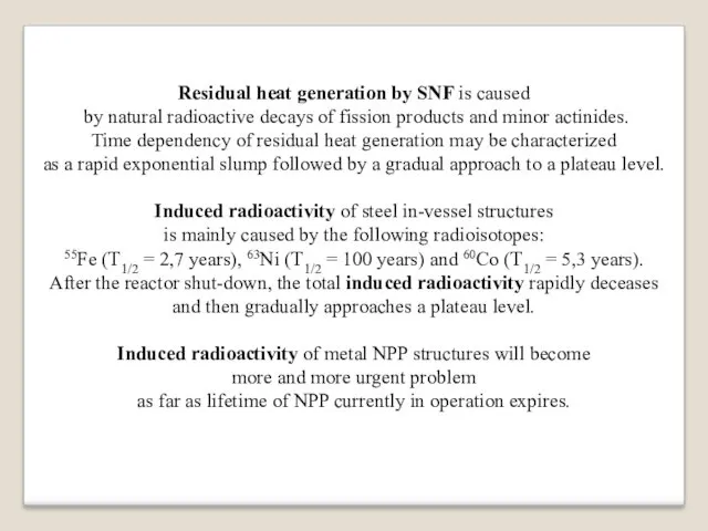
Residual heat generation by SNF is caused
by natural radioactive decays
of fission products and minor actinides.
Time dependency of residual heat generation may be characterized
as a rapid exponential slump followed by a gradual approach to a plateau level.
Induced radioactivity of steel in-vessel structures
is mainly caused by the following radioisotopes:
55Fe (Т1/2 = 2,7 years), 63Ni (Т1/2 = 100 years) and 60Co (Т1/2 = 5,3 years).
After the reactor shut-down, the total induced radioactivity rapidly deceases
and then gradually approaches a plateau level.
Induced radioactivity of metal NPP structures will become
more and more urgent problem
as far as lifetime of NPP currently in operation expires.
Слайд 16
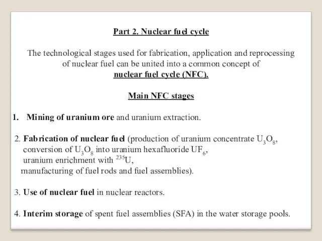
Part 2. Nuclear fuel cycle
The technological stages used for fabrication, application
and reprocessing
of nuclear fuel can be united into a common concept of
nuclear fuel cycle (NFC).
Main NFC stages
Mining of uranium ore and uranium extraction.
2. Fabrication of nuclear fuel (production of uranium concentrate U3O8,
conversion of U3O8 into uranium hexafluoride UF6,
uranium enrichment with 235U,
manufacturing of fuel rods and fuel assemblies).
3. Use of nuclear fuel in nuclear reactors.
4. Interim storage of spent fuel assemblies (SFA) in the water storage pools.
Слайд 17
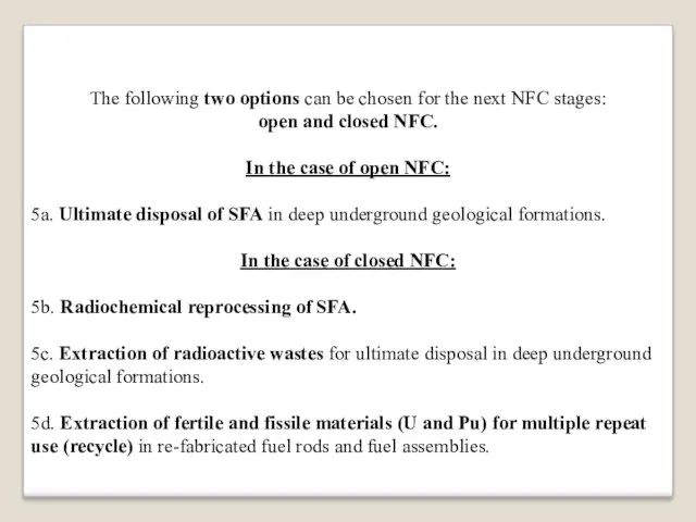
The following two options can be chosen for the next NFC
stages:
open and closed NFC.
In the case of open NFC:
5a. Ultimate disposal of SFA in deep underground geological formations.
In the case of closed NFC:
5b. Radiochemical reprocessing of SFA.
5c. Extraction of radioactive wastes for ultimate disposal in deep underground geological formations.
5d. Extraction of fertile and fissile materials (U and Pu) for multiple repeat use (recycle) in re-fabricated fuel rods and fuel assemblies.
Слайд 18
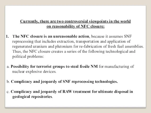
Currently, there are two controversial viewpoints in the world
on reasonability of
NFC closure:
The NFC closure is an unreasonable action, because it assumes SNF reprocessing that includes extraction, transportation and application of regenerated uranium and plutonium for re-fabrication of fresh fuel assemblies. Thus, the NFC closure creates a series of the following technological and political problems:
а. Possibility for terrorist groups to steal fissile NM for manufacturing of nuclear explosive devices.
b. Complicacy and jeopardy of SNF reprocessing technologies.
c. Complicacy and jeopardy of RAW treatment for ultimate disposal in geological repositories.
Слайд 19
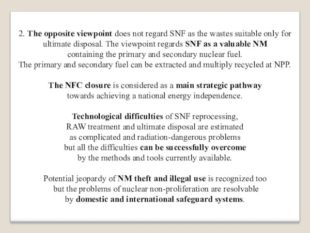
2. The opposite viewpoint does not regard SNF as the wastes
suitable only for ultimate disposal. The viewpoint regards SNF as a valuable NM
containing the primary and secondary nuclear fuel.
The primary and secondary fuel can be extracted and multiply recycled at NPP.
The NFC closure is considered as a main strategic pathway
towards achieving a national energy independence.
Technological difficulties of SNF reprocessing,
RAW treatment and ultimate disposal are estimated
as complicated and radiation-dangerous problems
but all the difficulties can be successfully overcome
by the methods and tools currently available.
Potential jeopardy of NM theft and illegal use is recognized too
but the problems of nuclear non-proliferation are resolvable
by domestic and international safeguard systems.
Слайд 20
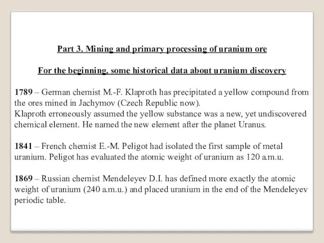
Part 3. Mining and primary processing of uranium ore
For the
beginning, some historical data about uranium discovery
1789 – German chemist M.-F. Klaproth has precipitated a yellow compound from the ores mined in Jachymov (Czech Republic now).
Klaproth erroneously assumed the yellow substance was a new, yet undiscovered chemical element. He named the new element after the planet Uranus.
1841 – French chemist E.-M. Peligot had isolated the first sample of metal uranium. Peligot has evaluated the atomic weight of uranium as 120 a.m.u.
1869 – Russian chemist Mendeleyev D.I. has defined more exactly the atomic weight of uranium (240 a.m.u.) and placed uranium in the end of the Mendeleyev periodic table.
Слайд 21
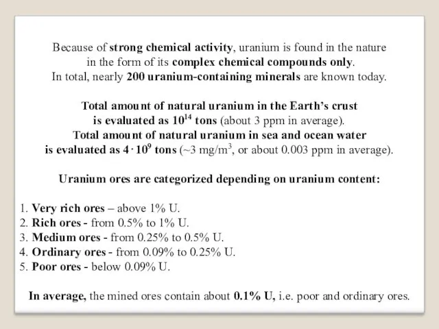
Because of strong chemical activity, uranium is found in the nature
in the form of its complex chemical compounds only.
In total, nearly 200 uranium-containing minerals are known today.
Total amount of natural uranium in the Earth’s crust
is evaluated as 1014 tons (about 3 ppm in average).
Total amount of natural uranium in sea and ocean water
is evaluated as 4⋅109 tons (~3 mg/m3, or about 0.003 ppm in average).
Uranium ores are categorized depending on uranium content:
1. Very rich ores – above 1% U.
2. Rich ores - from 0.5% to 1% U.
3. Medium ores - from 0.25% to 0.5% U.
4. Ordinary ores - from 0.09% to 0.25% U.
5. Poor ores - below 0.09% U.
In average, the mined ores contain about 0.1% U, i.e. poor and ordinary ores.
Слайд 22
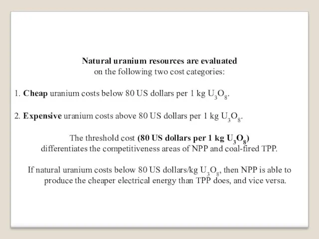
Natural uranium resources are evaluated
on the following two cost categories:
1. Cheap
uranium costs below 80 US dollars per 1 kg U3O8.
2. Expensive uranium costs above 80 US dollars per 1 kg U3O8.
The threshold cost (80 US dollars per 1 kg U3O8)
differentiates the competitiveness areas of NPP and coal-fired TPP.
If natural uranium costs below 80 US dollars/kg U3O8, then NPP is able to produce the cheaper electrical energy than TPP does, and vice versa.
Слайд 23
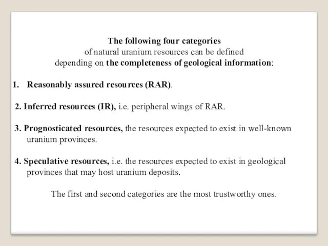
The following four categories
of natural uranium resources can be defined
depending on
the completeness of geological information:
Reasonably assured resources (RAR).
2. Inferred resources (IR), i.e. peripheral wings of RAR.
3. Prognosticated resources, the resources expected to exist in well-known uranium provinces.
4. Speculative resources, i.e. the resources expected to exist in geological provinces that may host uranium deposits.
The first and second categories are the most trustworthy ones.
Слайд 24
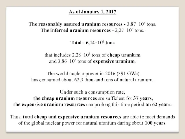
As of January 1, 2017
The reasonably assured uranium resources -
3,87⋅106 tons.
The inferred uranium resources - 2,27⋅106 tons.
Total - 6,14⋅106 tons
that includes 2,28⋅106 tons of cheap uranium
and 3,86⋅106 tons of expensive uranium.
The world nuclear power in 2016 (391 GWe)
has consumed about 62,3 thousand tons of natural uranium.
Under such a consumption rate,
the cheap uranium resources are sufficient for 37 years,
the expensive uranium resources can prolong this time period on 62 years.
Thus, total cheap and expensive uranium resources are able to meet demands of the global nuclear power for natural uranium during about 100 years.
Слайд 25
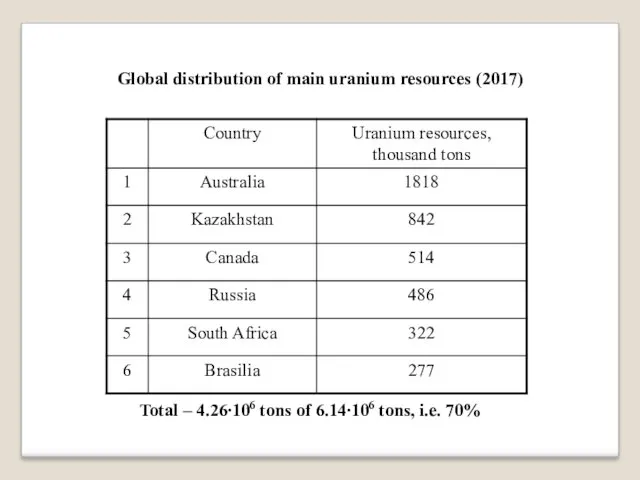
Global distribution of main uranium resources (2017)
Total – 4.26∙106 tons of
6.14∙106 tons, i.e. 70%
Слайд 26
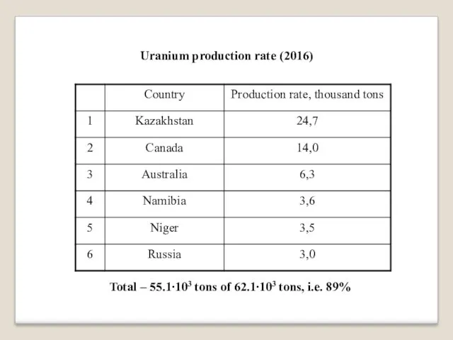
Uranium production rate (2016)
Total – 55.1∙103 tons of 62.1∙103 tons, i.e.
89%
Слайд 27
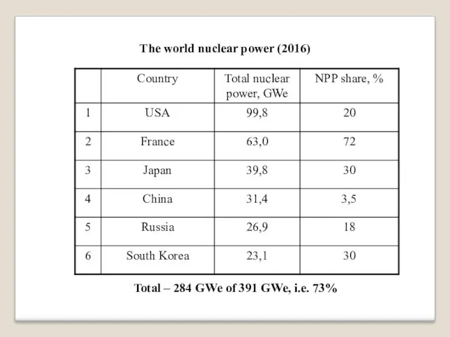
The world nuclear power (2016)
Total – 284 GWe of 391 GWe,
i.e. 73%
Слайд 28
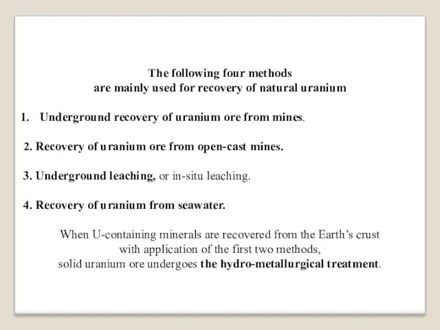
The following four methods
are mainly used for recovery of natural uranium
Underground
recovery of uranium ore from mines.
2. Recovery of uranium ore from open-cast mines.
3. Underground leaching, or in-situ leaching.
4. Recovery of uranium from seawater.
When U-containing minerals are recovered from the Earth’s crust
with application of the first two methods,
solid uranium ore undergoes the hydro-metallurgical treatment.
Слайд 29
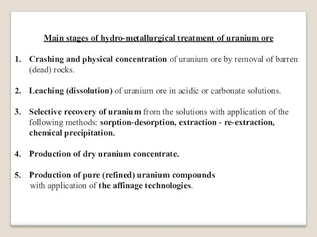
Main stages of hydro-metallurgical treatment of uranium ore
Crashing and physical concentration
of uranium ore by removal of barren (dead) rocks.
Leaching (dissolution) of uranium ore in acidic or carbonate solutions.
Selective recovery of uranium from the solutions with application of the following methods: sorption-desorption, extraction - re-extraction, chemical precipitation.
Production of dry uranium concentrate.
Production of pure (refined) uranium compounds
with application of the affinage technologies.
Слайд 30
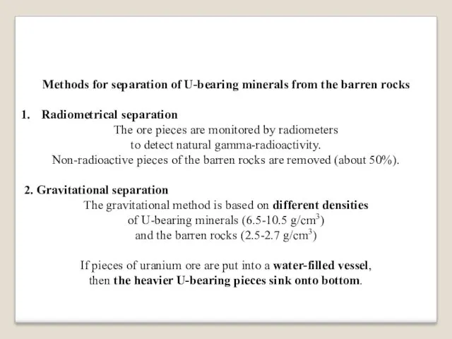
Methods for separation of U-bearing minerals from the barren rocks
Radiometrical separation
The ore pieces are monitored by radiometers
to detect natural gamma-radioactivity.
Non-radioactive pieces of the barren rocks are removed (about 50%).
2. Gravitational separation
The gravitational method is based on different densities
of U-bearing minerals (6.5-10.5 g/cm3)
and the barren rocks (2.5-2.7 g/cm3)
If pieces of uranium ore are put into a water-filled vessel,
then the heavier U-bearing pieces sink onto bottom.
Слайд 31
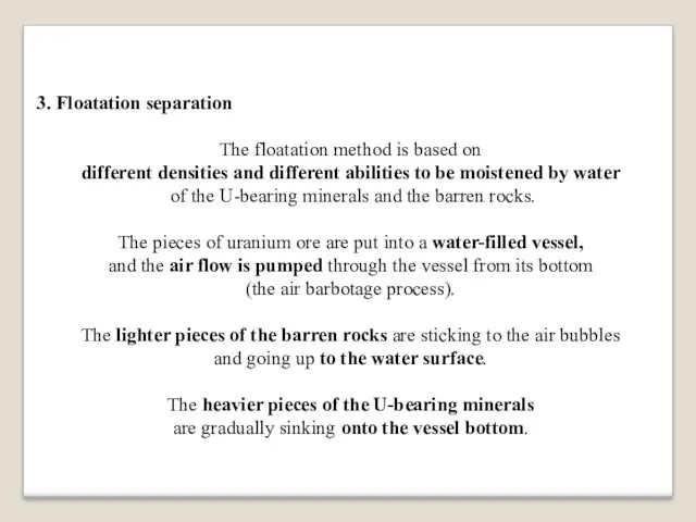
3. Floatation separation
The floatation method is based on
different densities and different
abilities to be moistened by water
of the U-bearing minerals and the barren rocks.
The pieces of uranium ore are put into a water-filled vessel,
and the air flow is pumped through the vessel from its bottom
(the air barbotage process).
The lighter pieces of the barren rocks are sticking to the air bubbles
and going up to the water surface.
The heavier pieces of the U-bearing minerals
are gradually sinking onto the vessel bottom.
Слайд 32
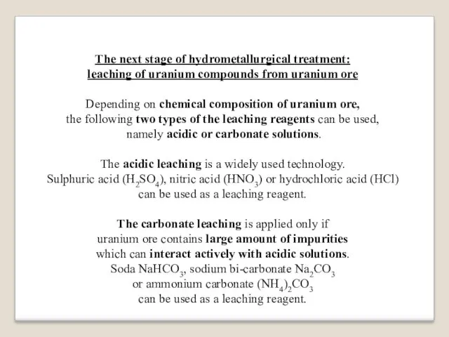
The next stage of hydrometallurgical treatment:
leaching of uranium compounds from uranium
ore
Depending on chemical composition of uranium ore,
the following two types of the leaching reagents can be used,
namely acidic or carbonate solutions.
The acidic leaching is a widely used technology.
Sulphuric acid (H2SO4), nitric acid (HNO3) or hydrochloric acid (HCl)
can be used as a leaching reagent.
The carbonate leaching is applied only if
uranium ore contains large amount of impurities
which can interact actively with acidic solutions.
Soda NaHCO3, sodium bi-carbonate Na2CO3
or ammonium carbonate (NH4)2CO3
can be used as a leaching reagent.
Слайд 33
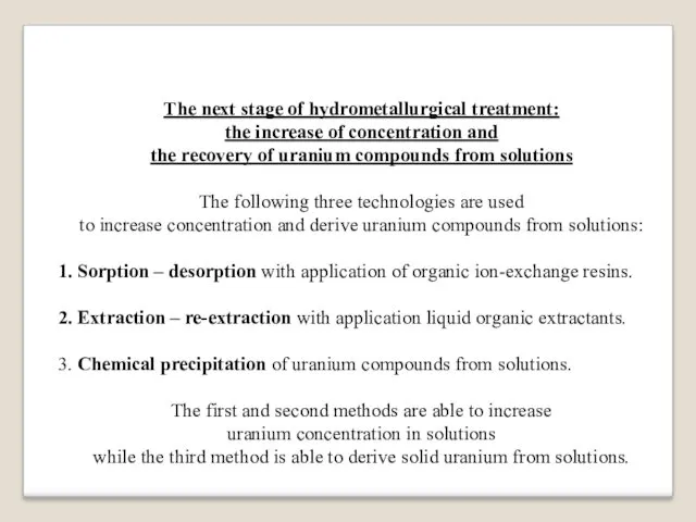
The next stage of hydrometallurgical treatment:
the increase of concentration and
the
recovery of uranium compounds from solutions
The following three technologies are used
to increase concentration and derive uranium compounds from solutions:
Sorption – desorption with application of organic ion-exchange resins.
Extraction – re-extraction with application liquid organic extractants.
Chemical precipitation of uranium compounds from solutions.
The first and second methods are able to increase
uranium concentration in solutions
while the third method is able to derive solid uranium from solutions.
Слайд 34
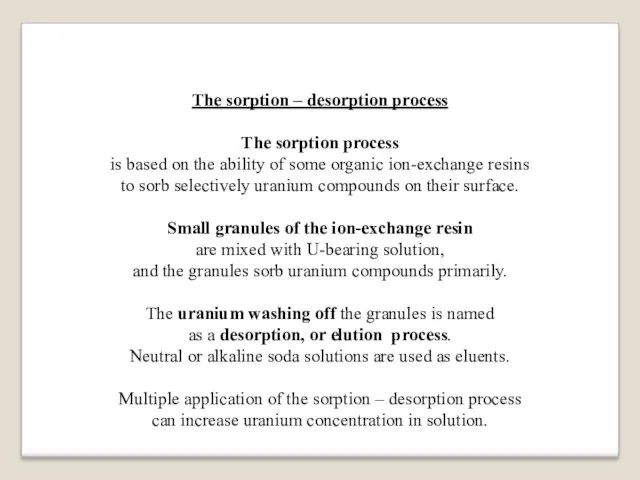
The sorption – desorption process
The sorption process
is based on the
ability of some organic ion-exchange resins
to sorb selectively uranium compounds on their surface.
Small granules of the ion-exchange resin
are mixed with U-bearing solution,
and the granules sorb uranium compounds primarily.
The uranium washing off the granules is named
as a desorption, or elution process.
Neutral or alkaline soda solutions are used as eluents.
Multiple application of the sorption – desorption process
can increase uranium concentration in solution.
Слайд 35
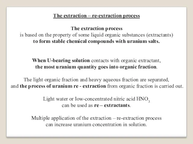
The extraction – re-extraction process
The extraction process
is based on the property
of some liquid organic substances (extractants)
to form stable chemical compounds with uranium salts.
When U-bearing solution contacts with organic extractant,
the most uranium quantity goes into organic fraction.
The light organic fraction and heavy aqueous fraction are separated,
and the process of uranium re - extraction from organic fraction is carried out.
Light water or low-concentrated nitric acid HNO3
can be used as re – extractants.
Multiple application of the extraction – re-extraction process
can increase uranium concentration in solution.
Слайд 36
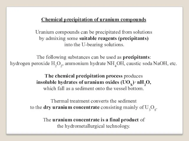
Chemical precipitation of uranium compounds
Uranium compounds can be precipitated from solutions
by
admixing some suitable reagents (precipitants)
into the U-bearing solutions.
The following substances can be used as precipitants:
hydrogen peroxide H2O2, ammonium hydrate NH4OH, caustic soda NaOH, etc.
The chemical precipitation process produces
insoluble hydrates of uranium oxides (UOX)⋅nH2O,
which fall as a sediment onto the vessel bottom.
Thermal treatment converts the sediment
to the dry uranium concentrate consisting mainly of U3O8.
The uranium concentrate is a final product of
the hydrometallurgical technology.
Слайд 37
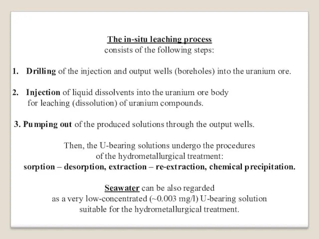
The in-situ leaching process
consists of the following steps:
Drilling of the injection
and output wells (boreholes) into the uranium ore.
Injection of liquid dissolvents into the uranium ore body
for leaching (dissolution) of uranium compounds.
3. Pumping out of the produced solutions through the output wells.
Then, the U-bearing solutions undergo the procedures
of the hydrometallurgical treatment:
sorption – desorption, extraction – re-extraction, chemical precipitation.
Seawater can be also regarded
as a very low-concentrated (~0.003 mg/l) U-bearing solution
suitable for the hydrometallurgical treatment.
Слайд 38
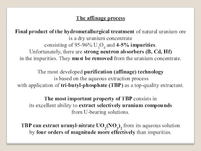
The affinage process
Final product of the hydrometallurgical treatment of natural uranium
ore
is a dry uranium concentrate
consisting of 95-96% U3O8 and 4-5% impurities.
Unfortunately, there are strong neutron absorbers (B, Cd, Hf)
in the impurities. They must be removed from the uranium concentrate.
The most developed purification (affinage) technology
is based on the aqueous extraction process
with application of tri-butyl-phosphate (TBP) as a top-quality extractant.
The most important property of TBP consists in
its excellent ability to extract selectively uranium compounds
from U-bearing solutions.
TBP can extract uranyl-nitrate UO2(NO3)2 from its aqueous solution
by four orders of magnitude more effectively than impurities.
Слайд 39
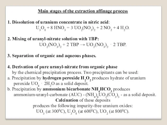
Main stages of the extraction affinage process
1. Dissolution of uranium concentrate
in nitric acid:
U3O8 + 8 HNO3 = 3 UO2(NO3)2 + 2 NO2 + 4 H2O.
2. Mixing of uranyl-nitrate solution with TBP:
UO2(NO3)2 + 2 TBP → UO2(NO3)2 ⋅ 2 TBP.
3. Separation of organic and aqueous phases.
4. Derivation of pure uranyl-nitrate from organic phase
by the chemical precipitation process. Two precipitants can be used:
a. Precipitation by hydrogen peroxide H2O2 produces hydrate of uranium peroxide UO4 ⋅ 2H2O as a solid deposit.
b. Precipitation by ammonium bicarbonate NH4HCO3 produces ammonium-uranyl-carbonate (AUC) - (NH4)4UO2(CO3)3 - as a solid deposit.
Calcination of these deposits
produces the following impurity-free uranium oxides:
UO3 (at 3000С), U3O8 (at 6000С), UO2 (at 8000С).
Слайд 40
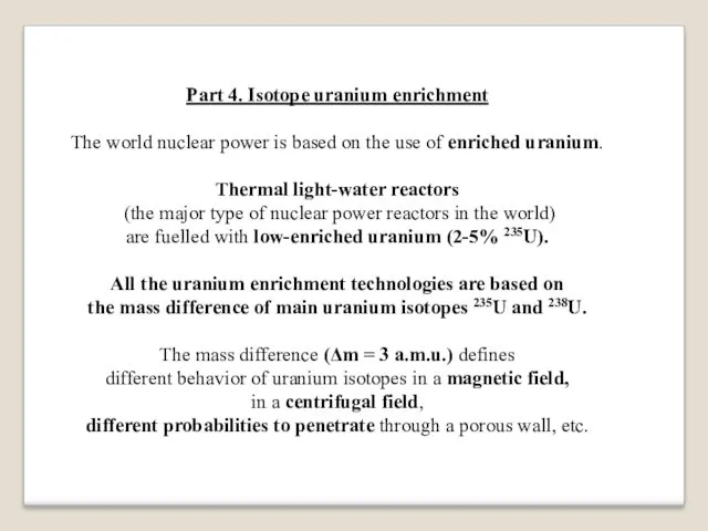
Part 4. Isotope uranium enrichment
The world nuclear power is based on
the use of enriched uranium.
Thermal light-water reactors
(the major type of nuclear power reactors in the world)
are fuelled with low-enriched uranium (2-5% 235U).
All the uranium enrichment technologies are based on
the mass difference of main uranium isotopes 235U and 238U.
The mass difference (Δm = 3 a.m.u.) defines
different behavior of uranium isotopes in a magnetic field,
in a centrifugal field,
different probabilities to penetrate through a porous wall, etc.
Слайд 41
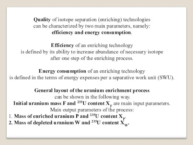
Quality of isotope separation (enriching) technologies
can be characterized by two main
parameters, namely:
efficiency and energy consumption.
Efficiency of an enriching technology
is defined by its ability to increase abundance of necessary isotope
after one step of the enriching process.
Energy consumption of an enriching technology
is defined in the terms of energy expenses per a separative work unit (SWU).
General layout of the uranium enrichment process
can be shown in the following way.
Initial uranium mass F and 235U content XF are main input parameters.
Main output parameters of the process:
1. Mass of enriched uranium P and 235U content XP.
2. Mass of depleted uranium W and 235U content XW.
Слайд 42
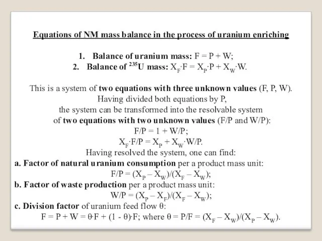
Equations of NM mass balance in the process of uranium enriching
Balance
of uranium mass: F = P + W;
Balance of 235U mass: XF∙F = XP∙P + XW∙W.
This is a system of two equations with three unknown values (F, P, W).
Having divided both equations by P,
the system can be transformed into the resolvable system
of two equations with two unknown values (F/P and W/P):
F/P = 1 + W/P;
XF∙F/P = XP + XW∙W/P.
Having resolved the system, one can find:
a. Factor of natural uranium consumption per a product mass unit:
F/P = (XP – XW)/(XF – XW);
b. Factor of waste production per a product mass unit:
W/P = (XP – XF)/(XF – XW);
c. Division factor of uranium feed flow θ:
F = P + W = θ∙F + (1 - θ)∙F; where θ = P/F = (XF – XW)/(XP – XW).
Слайд 43

Examples:
a. Production of weapon-grade uranium from natural uranium:
XF = 0.7%; XP
= 90%; XW = 0.25%.
Then, F/P = (XP – XW)/(XF – XW) = 89.75 / 0.46 ≈ 195.
This means that production of 25 kg
(mass of weapon-grade uranium for one nuclear explosive device)
requires nearly 5 tons of natural uranium, or 5000 tons of natural uranium ore.
b. Production of reactor-grade uranium from natural uranium:
XF = 0.7%; XP = 4%; XW = 0.25%.
Then, θ = (XF – XW)/(XP – XW) ≈ 0.12;
This means that 120 kg of low-enriched uranium (4% 235U)
and 880 kg of depleted uranium (0.25% 235U)
can be obtained from 1000 kg of natural uranium.
Слайд 44
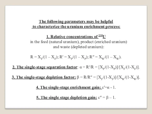
The following parameters may be helpful
to characterize the uranium enrichment
process:
1. Relative concentrations of 235U
in the feed (natural uranium), product (enriched uranium)
and waste (depleted uranium):
R = XF/(1 – XF); R′ = XP/(1 – XP); R′′ = XW/(1 – XW).
2. The single-stage separation factor: α = R′/R = [XP/(1-XP)]/[XF/(1-XF)].
3. The single-stage depletion factor: β = R/R′′ = [XF/(1-XF)]/[XW/(1-XW)].
4. The single-stage enrichment gain: ε′=α - 1.
5. The single stage depletion gain: ε′′ = β – 1.
Слайд 45
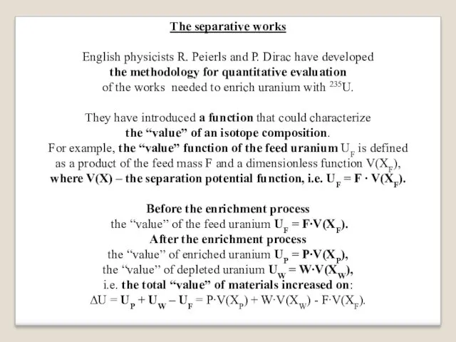
The separative works
English physicists R. Peierls and P. Dirac have developed
the
methodology for quantitative evaluation
of the works needed to enrich uranium with 235U.
They have introduced a function that could characterize
the “value” of an isotope composition.
For example, the “value” function of the feed uranium UF is defined
as a product of the feed mass F and a dimensionless function V(XF),
where V(X) – the separation potential function, i.e. UF = F ∙ V(XF).
Before the enrichment process
the “value” of the feed uranium UF = F∙V(XF).
After the enrichment process
the “value” of enriched uranium UP = P∙V(XP),
the “value” of depleted uranium UW = W∙V(XW),
i.e. the total “value” of materials increased on:
ΔU = UP + UW – UF = P∙V(XP) + W∙V(XW) - F∙V(XF).
Слайд 46
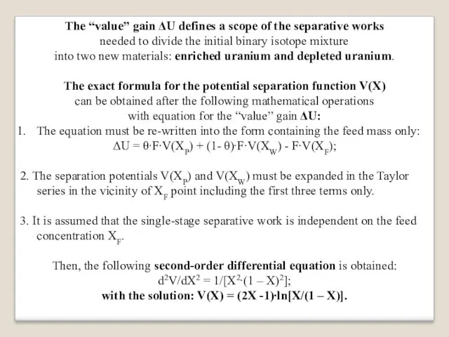
The “value” gain ΔU defines a scope of the separative works
needed
to divide the initial binary isotope mixture
into two new materials: enriched uranium and depleted uranium.
The exact formula for the potential separation function V(X)
can be obtained after the following mathematical operations
with equation for the “value” gain ΔU:
The equation must be re-written into the form containing the feed mass only:
ΔU = θ∙F∙V(XP) + (1- θ)∙F∙V(XW) - F∙V(XF);
2. The separation potentials V(XP) and V(XW) must be expanded in the Taylor series in the vicinity of XF point including the first three terms only.
3. It is assumed that the single-stage separative work is independent on the feed concentration XF.
Then, the following second-order differential equation is obtained:
d2V/dX2 = 1/[X2∙(1 – X)2];
with the solution: V(X) = (2X -1)∙ln[X/(1 – X)].
Слайд 47
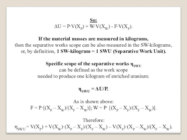
So:
ΔU = P∙V(XP) + W∙V(XW) - F∙V(XF).
If the material masses are
measured in kilograms,
then the separative works scope can be also measured in the SW-kilograms,
or, by definition, 1 SW-kilogram = 1 SWU (Separative Work Unit).
Specific scope of the separative works ηSWU
can be defined as the work scope
needed to produce one kilogram of enriched uranium:
ηSWU = ΔU/P.
As is shown above:
F = P∙[(XP – XW)/(XF – XW)]; W = P∙ [(XP – XF)/(XF – XW)].
Therefore:
ηSWU = V(XP) + V(XW)·(XP – XF)/(XF – XW) – V(XF)·(XP – XW)/(XF – XW).
Слайд 48
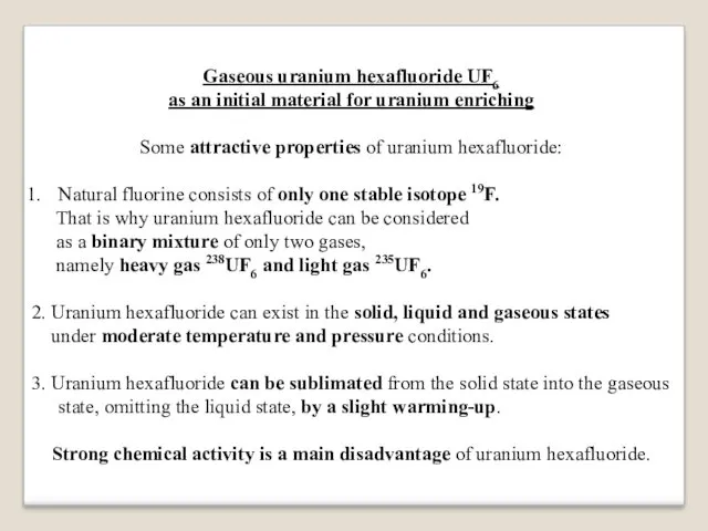
Gaseous uranium hexafluoride UF6
as an initial material for uranium enriching
Some
attractive properties of uranium hexafluoride:
Natural fluorine consists of only one stable isotope 19F.
That is why uranium hexafluoride can be considered
as a binary mixture of only two gases,
namely heavy gas 238UF6 and light gas 235UF6.
2. Uranium hexafluoride can exist in the solid, liquid and gaseous states
under moderate temperature and pressure conditions.
3. Uranium hexafluoride can be sublimated from the solid state into the gaseous state, omitting the liquid state, by a slight warming-up.
Strong chemical activity is a main disadvantage of uranium hexafluoride.
Слайд 49
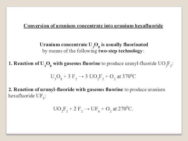
Conversion of uranium concentrate into uranium hexafluoride
Uranium concentrate U3O8 is usually
fluorinated
by means of the following two-step technology:
1. Reaction of U3O8 with gaseous fluorine to produce uranyl-fluoride UO2F2:
U3O8 + 3 F2 → 3 UO2F2 + O2 at 3700С
2. Reaction of uranyl-fluoride with gaseous fluorine to produce uranium hexafluoride UF6:
UO2F2 + 2 F2 → UF6 + O2 at 2700С.
Слайд 50
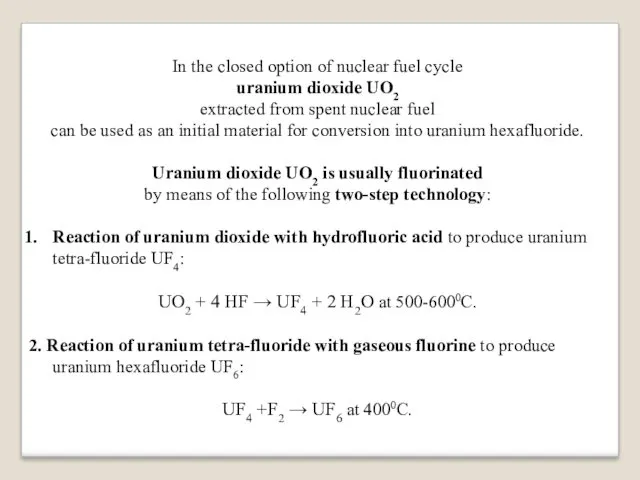
In the closed option of nuclear fuel cycle
uranium dioxide UO2
extracted
from spent nuclear fuel
can be used as an initial material for conversion into uranium hexafluoride.
Uranium dioxide UO2 is usually fluorinated
by means of the following two-step technology:
Reaction of uranium dioxide with hydrofluoric acid to produce uranium tetra-fluoride UF4:
UO2 + 4 HF → UF4 + 2 H2O at 500-6000С.
2. Reaction of uranium tetra-fluoride with gaseous fluorine to produce uranium hexafluoride UF6:
UF4 +F2 → UF6 at 4000С.
Слайд 51
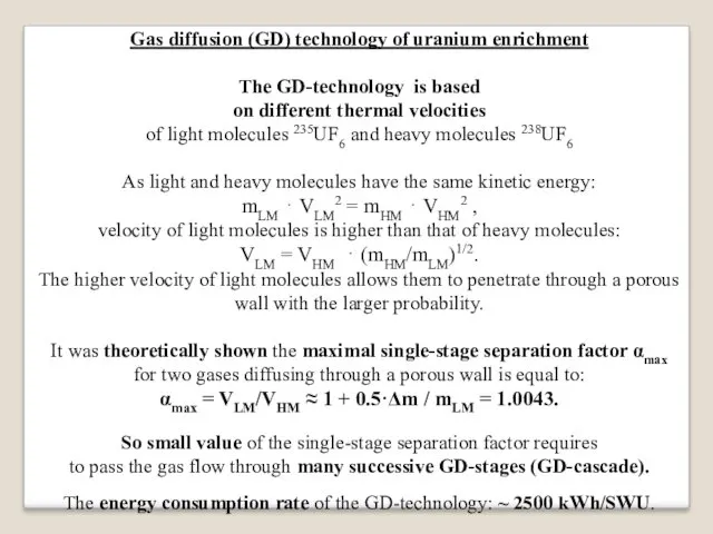
Gas diffusion (GD) technology of uranium enrichment
The GD-technology is based
on different
thermal velocities
of light molecules 235UF6 and heavy molecules 238UF6
As light and heavy molecules have the same kinetic energy:
mLM ⋅ VLM2 = mHM ⋅ VHM2 ,
velocity of light molecules is higher than that of heavy molecules:
VLM = VHM ⋅ (mHM/mLM)1/2.
The higher velocity of light molecules allows them to penetrate through a porous wall with the larger probability.
It was theoretically shown the maximal single-stage separation factor αmax
for two gases diffusing through a porous wall is equal to:
αmax = VLM/VHM ≈ 1 + 0.5·Δm / mLM = 1.0043.
So small value of the single-stage separation factor requires
to pass the gas flow through many successive GD-stages (GD-cascade).
The energy consumption rate of the GD-technology: ~ 2500 kWh/SWU.
Слайд 52
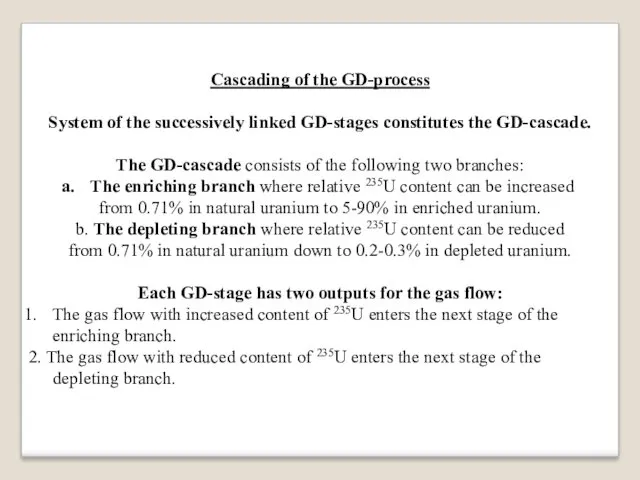
Cascading of the GD-process
System of the successively linked GD-stages constitutes the
GD-cascade.
The GD-cascade consists of the following two branches:
The enriching branch where relative 235U content can be increased
from 0.71% in natural uranium to 5-90% in enriched uranium.
b. The depleting branch where relative 235U content can be reduced
from 0.71% in natural uranium down to 0.2-0.3% in depleted uranium.
Each GD-stage has two outputs for the gas flow:
The gas flow with increased content of 235U enters the next stage of the enriching branch.
2. The gas flow with reduced content of 235U enters the next stage of the depleting branch.
Слайд 53
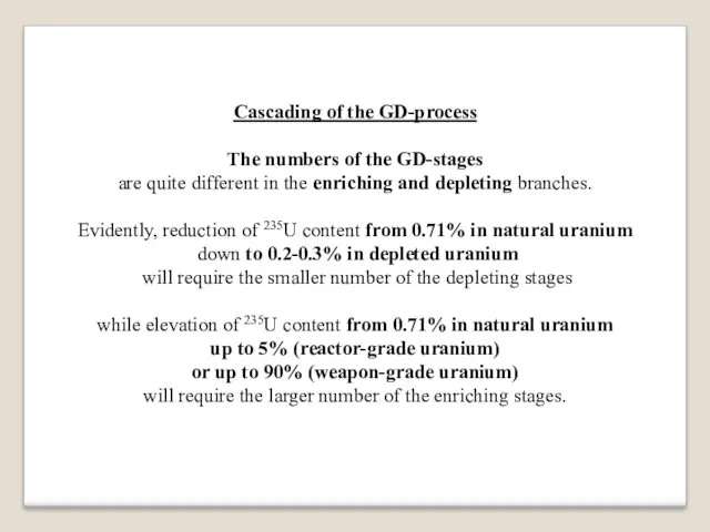
Cascading of the GD-process
The numbers of the GD-stages
are quite different in
the enriching and depleting branches.
Evidently, reduction of 235U content from 0.71% in natural uranium
down to 0.2-0.3% in depleted uranium
will require the smaller number of the depleting stages
while elevation of 235U content from 0.71% in natural uranium
up to 5% (reactor-grade uranium)
or up to 90% (weapon-grade uranium)
will require the larger number of the enriching stages.
Слайд 54
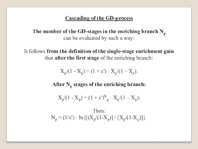
Cascading of the GD-process
The number of the GD-stages in the enriching
branch NP
can be evaluated by such a way:
It follows from the definition of the single-stage enrichment gain
that after the first stage of the enriching branch:
XP/(1 - XP) = (1 + ε′) · XF/(1 – XF).
After NP stages of the enriching branch:
XP/(1 - XP) = (1 + ε′)NP · XF/(1 – XF).
Then:
NP ≈ (1/ε′) · ln{[(XP/(1-XP)] / [XF/(1-XF)]}.
Слайд 55
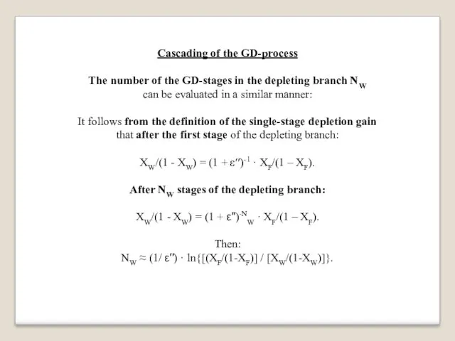
Cascading of the GD-process
The number of the GD-stages in the depleting
branch NW
can be evaluated in a similar manner:
It follows from the definition of the single-stage depletion gain
that after the first stage of the depleting branch:
XW/(1 - XW) = (1 + ε′′)-1 · XF/(1 – XF).
After NW stages of the depleting branch:
XW/(1 - XW) = (1 + ε′′)-NW · XF/(1 – XF).
Then:
NW ≈ (1/ ε′′) · ln{[(XF/(1-XF)] / [XW/(1-XW)]}.
Слайд 56
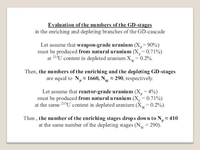
Evaluation of the numbers of the GD-stages
in the enriching and depleting
branches of the GD-cascade
Let assume that weapon-grade uranium (XP = 90%)
must be produced from natural uranium (XF = 0.71%)
at 235U content in depleted uranium XW = 0.2%.
Then, the numbers of the enriching and the depleting GD-stages
are equal to NP ≈ 1660, NW ≈ 290, respectively.
Let assume that reactor-grade uranium (XP = 4%)
must be produced from natural uranium (XF = 0.71%)
at the same 235U content in depleted uranium (XW = 0.2%).
Then , the number of the enriching stages drops down to NP ≈ 410
at the same number of the depleting stages (NW ≈ 290).
Слайд 57

Uranium enriching in gas centrifuges (GC)
If a cylindrical vessel (centrifuge)
containing
a binary mixture of light and heavy gases (235UF6 and 238UF6)
rotates with a large angular velocity ω,
then heavy molecules are driven back to the vessel wall
while light molecules remain in the central zone.
The centrifugal force F acts on elementary volume of the gas mixture:
F(r) = γ(r) ∙ω2∙r.
The pressure on the gas components:
dP(r)/dr = F(r) = γ(r)∙ω2∙r.
Densities of the gas components can be derived
from the Mendeleyev-Clapeyron equation:
γ(r) = m/V = P(r)∙M/RT
Then, differential equation for the gas pressure can be re-written:
dP(r)/dr = P(r)∙M∙ω2∙r/2RT,
and solved:
P(r) = P(0)∙exp(M∙ω2∙r2/2RT) = P(0)∙exp(M∙V2(r)/2RT).
Слайд 58
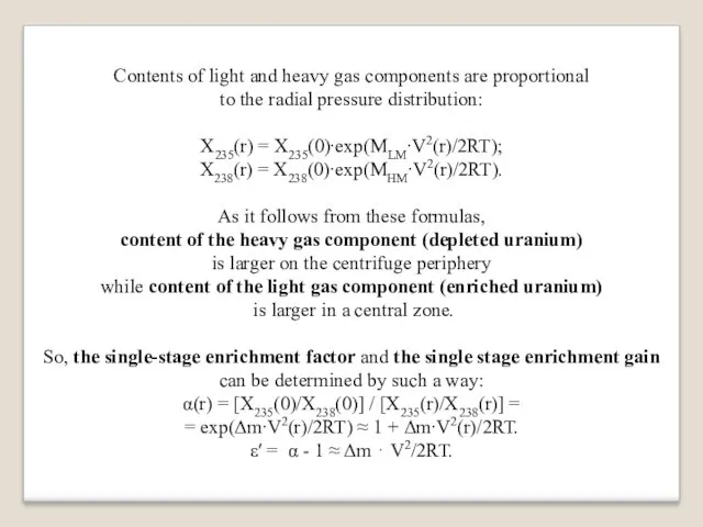
Contents of light and heavy gas components are proportional
to the radial
pressure distribution:
X235(r) = X235(0)∙exp(MLM∙V2(r)/2RT);
X238(r) = X238(0)∙exp(MHM∙V2(r)/2RT).
As it follows from these formulas,
content of the heavy gas component (depleted uranium)
is larger on the centrifuge periphery
while content of the light gas component (enriched uranium)
is larger in a central zone.
So, the single-stage enrichment factor and the single stage enrichment gain can be determined by such a way:
α(r) = [X235(0)/X238(0)] / [X235(r)/X238(r)] =
= exp(Δm∙V2(r)/2RT) ≈ 1 + Δm∙V2(r)/2RT.
ε′ = α - 1 ≈ Δm ⋅ V2/2RT.
Слайд 59
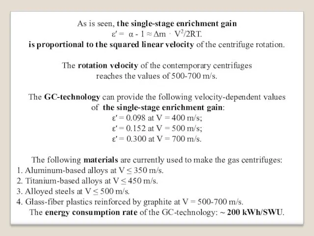
As is seen, the single-stage enrichment gain
ε′ = α -
1 ≈ Δm ⋅ V2/2RT.
is proportional to the squared linear velocity of the centrifuge rotation.
The rotation velocity of the contemporary centrifuges
reaches the values of 500-700 m/s.
The GC-technology can provide the following velocity-dependent values
of the single-stage enrichment gain:
ε′ = 0.098 at V = 400 m/s;
ε′ = 0.152 at V = 500 m/s;
ε′ = 0.300 at V = 700 m/s.
The following materials are currently used to make the gas centrifuges:
1. Aluminum-based alloys at V ≤ 350 m/s.
2. Titanium-based alloys at V ≤ 450 m/s.
3. Alloyed steels at V ≤ 500 m/s.
4. Glass-fiber plastics reinforced by graphite at V = 500-700 m/s.
The energy consumption rate of the GC-technology: ~ 200 kWh/SWU.
Слайд 60
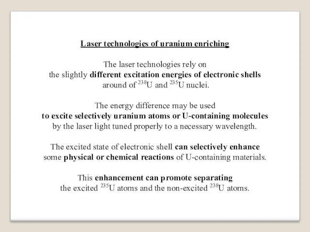
Laser technologies of uranium enriching
The laser technologies rely on
the slightly
different excitation energies of electronic shells
around of 238U and 235U nuclei.
The energy difference may be used
to excite selectively uranium atoms or U-containing molecules
by the laser light tuned properly to a necessary wavelength.
The excited state of electronic shell can selectively enhance
some physical or chemical reactions of U-containing materials.
This enhancement can promote separating
the excited 235U atoms and the non-excited 238U atoms.
Слайд 61
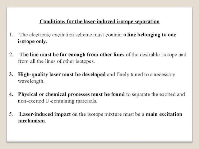
Conditions for the laser-induced isotope separation
The electronic excitation scheme must
contain a line belonging to one isotope only.
The line must be far enough from other lines of the desirable isotope and from all the lines of other isotopes.
High-quality laser must be developed and finely tuned to a necessary wavelength.
Physical or chemical processes must be found to separate the excited and non-excited U-containing materials.
Laser-induced impact on the isotope mixture must be a main excitation mechanism.
Слайд 62

Atomic Vapor Laser Isotope Separation (AVLIS) technology
The AVLIS technology includes the
following stages:
High-temperature vacuum evaporation of uranium atoms:
Accelerated electron beam knocks uranium atoms out of U-Re alloy.
2. Irradiation by xenon laser (λ ~ 3780 Ǻ, ultraviolet range).
235U atoms are selectively excited./
3. Irradiation by krypton laser (λ ~ 3500 Ǻ, ultraviolet range). The excited 235U atoms are selectively ionized.
4. Collection of 235U ions on an electrically charged plate.
Слайд 63
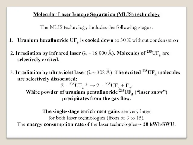
Molecular Laser Isotope Separation (MLIS) technology
The MLIS technology includes the following
stages:
Uranium hexafluoride UF6 is cooled down to 30 K without condensation.
2. Irradiation by infrared laser (λ ~ 16 000 Ǻ). Molecules of 235UF6 are selectively excited.
3. Irradiation by ultraviolet laser (λ ~ 308 Ǻ). The excited 235UF6 molecules are selectively dissociated:
2 ⋅ 235UF6 * → 2 ⋅ 235UF5 + F2.
White powder of uranium pentafluoride 235UF5 (“laser snow”)
precipitates from the gas flow.
The single-stage enrichment gains are very large
for both laser technologies (from от 3 to 15).
The energy consumption rate of the laser technologies ~ 20 kWh/SWU.
Слайд 64
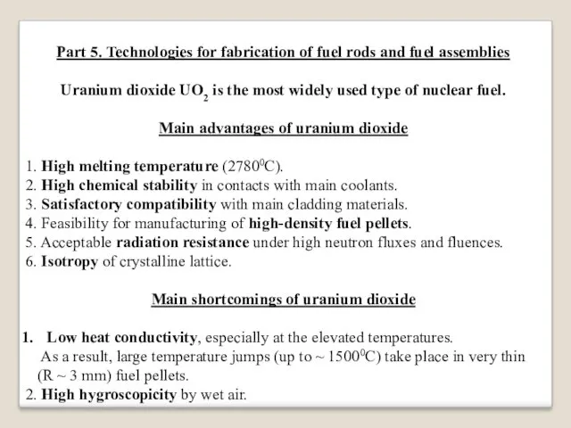
Part 5. Technologies for fabrication of fuel rods and fuel assemblies
Uranium
dioxide UO2 is the most widely used type of nuclear fuel.
Main advantages of uranium dioxide
1. High melting temperature (27800С).
2. High chemical stability in contacts with main coolants.
3. Satisfactory compatibility with main cladding materials.
4. Feasibility for manufacturing of high-density fuel pellets.
5. Acceptable radiation resistance under high neutron fluxes and fluences.
6. Isotropy of crystalline lattice.
Main shortcomings of uranium dioxide
Low heat conductivity, especially at the elevated temperatures.
As a result, large temperature jumps (up to ~ 15000C) take place in very thin
(R ~ 3 mm) fuel pellets.
2. High hygroscopicity by wet air.
Слайд 65
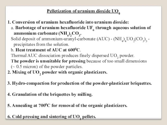
Pelletization of uranium dioxide UO2
1. Conversion of uranium hexafluoride into uranium
dioxide:
a. Barbotage of uranium hexafluoride UF6 through aqueous solution of ammonium carbonate (NH4)2CO3.
Solid deposit of ammonium-uranyl-carbonate (AUC) - (NH4)4UO2(CO3)3 - precipitates from the solution.
b. Heat treatment of AUC at 6000С.
Thermal AUC dissociation produces finely dispersed UO2 powder.
The powder is unsuitable for pressing because of too small dimensions
(~ 0.5 micron) of the powder particles.
2. Mixing of UO2 powder with organic plasticizers.
3. Hydro-compaction for production of the powder-plasticizer briquettes.
4. Granulation of the briquettes by milling.
5. Annealing at 7000С for removal of the organic plasticizers.
6. Cold pressing and sintering of UO2 pellets.
Слайд 66
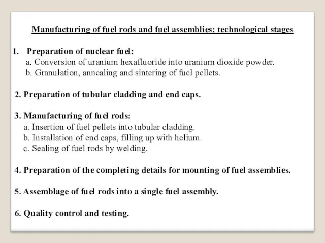
Manufacturing of fuel rods and fuel assemblies: technological stages
Preparation of nuclear
fuel:
a. Conversion of uranium hexafluoride into uranium dioxide powder.
b. Granulation, annealing and sintering of fuel pellets.
2. Preparation of tubular cladding and end caps.
3. Manufacturing of fuel rods:
a. Insertion of fuel pellets into tubular cladding.
b. Installation of end caps, filling up with helium.
c. Sealing of fuel rods by welding.
4. Preparation of the completing details for mounting of fuel assemblies.
5. Assemblage of fuel rods into a single fuel assembly.
6. Quality control and testing.
Слайд 67
Part 6. Technologies for the use of nuclear fuel in nuclear
reactors
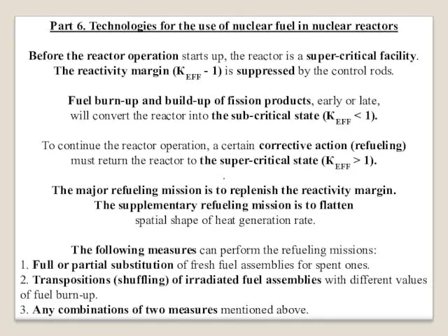
Before the reactor operation starts up, the reactor is a super-critical facility.
The reactivity margin (КEFF - 1) is suppressed by the control rods.
Fuel burn-up and build-up of fission products, early or late,
will convert the reactor into the sub-critical state (КEFF < 1).
To continue the reactor operation, a certain corrective action (refueling)
must return the reactor to the super-critical state (КEFF > 1).
.
The major refueling mission is to replenish the reactivity margin.
The supplementary refueling mission is to flatten
spatial shape of heat generation rate.
The following measures can perform the refueling missions:
1. Full or partial substitution of fresh fuel assemblies for spent ones.
2. Transpositions (shuffling) of irradiated fuel assemblies with different values of fuel burn-up.
3. Any combinations of two measures mentioned above.
Слайд 68
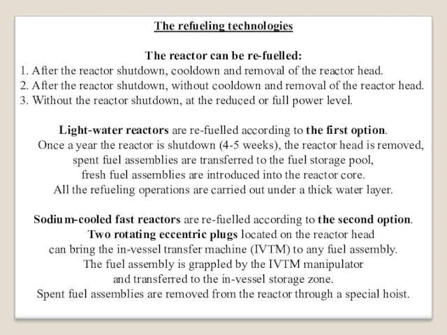
The refueling technologies
The reactor can be re-fuelled:
1. After the reactor shutdown,
cooldown and removal of the reactor head.
2. After the reactor shutdown, without cooldown and removal of the reactor head.
3. Without the reactor shutdown, at the reduced or full power level.
Light-water reactors are re-fuelled according to the first option.
Once a year the reactor is shutdown (4-5 weeks), the reactor head is removed, spent fuel assemblies are transferred to the fuel storage pool,
fresh fuel assemblies are introduced into the reactor core.
All the refueling operations are carried out under a thick water layer.
Sodium-cooled fast reactors are re-fuelled according to the second option.
Two rotating eccentric plugs located on the reactor head
can bring the in-vessel transfer machine (IVTM) to any fuel assembly.
The fuel assembly is grappled by the IVTM manipulator
and transferred to the in-vessel storage zone.
Spent fuel assemblies are removed from the reactor through a special hoist.
Слайд 69
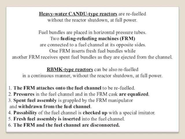
Heavy-water CANDU-type reactors are re-fuelled
without the reactor shutdown, at full power.
Fuel
bundles are placed in horizontal pressure tubes.
Two fueling-refueling machines (FRM)
are connected to a fuel channel at its opposite sides.
One FRM inserts fresh fuel bundles while
another FRM receives spent fuel bundles as they are ejected from the channel.
RBMK-type reactors can be also re-fuelled
in a continuous manner, without the reactor shutdown, at full power.
1. The FRM attaches onto the fuel channel to be re-fuelled.
2. Pressures in the fuel channel and in the FRM cask are equalized.
3. Spent fuel assembly is grappled by the FRM manipulator
and withdrawn from the fuel channel.
4. Passability of the fuel channel is checked up with a special imitator.
5. Fresh fuel assembly is inserted into the fuel channel.
6. The FRM and the fuel channel are disconnected.
Слайд 70
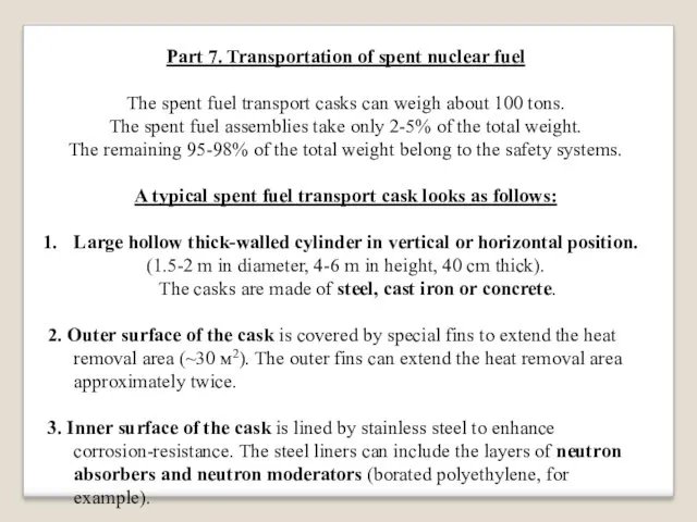
Part 7. Transportation of spent nuclear fuel
The spent fuel transport casks
can weigh about 100 tons.
The spent fuel assemblies take only 2-5% of the total weight.
The remaining 95-98% of the total weight belong to the safety systems.
A typical spent fuel transport cask looks as follows:
Large hollow thick-walled cylinder in vertical or horizontal position.
(1.5-2 m in diameter, 4-6 m in height, 40 cm thick).
The casks are made of steel, cast iron or concrete.
2. Outer surface of the cask is covered by special fins to extend the heat removal area (~30 м2). The outer fins can extend the heat removal area approximately twice.
3. Inner surface of the cask is lined by stainless steel to enhance corrosion-resistance. The steel liners can include the layers of neutron absorbers and neutron moderators (borated polyethylene, for example).
Слайд 71
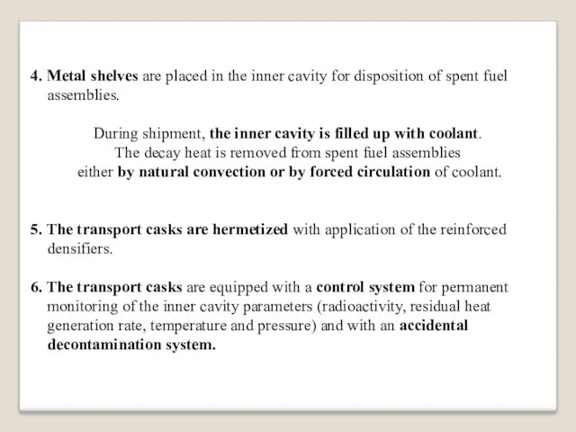
4. Metal shelves are placed in the inner cavity for disposition
of spent fuel assemblies.
During shipment, the inner cavity is filled up with coolant.
The decay heat is removed from spent fuel assemblies
either by natural convection or by forced circulation of coolant.
5. The transport casks are hermetized with application of the reinforced densifiers.
6. The transport casks are equipped with a control system for permanent monitoring of the inner cavity parameters (radioactivity, residual heat generation rate, temperature and pressure) and with an accidental decontamination system.
Слайд 72
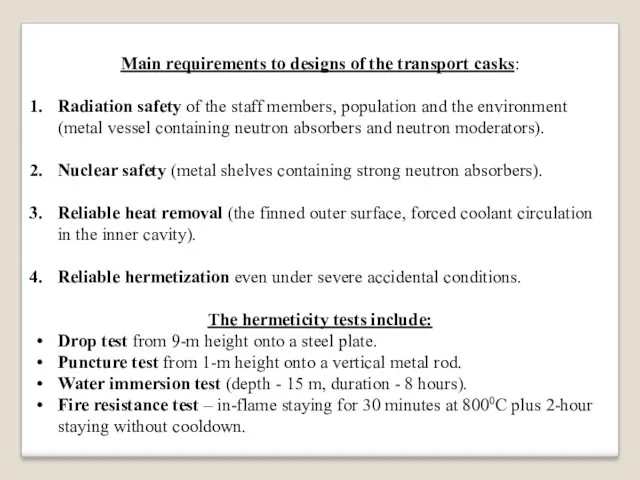
Main requirements to designs of the transport casks:
Radiation safety of the
staff members, population and the environment (metal vessel containing neutron absorbers and neutron moderators).
Nuclear safety (metal shelves containing strong neutron absorbers).
Reliable heat removal (the finned outer surface, forced coolant circulation in the inner cavity).
Reliable hermetization even under severe accidental conditions.
The hermeticity tests include:
Drop test from 9-m height onto a steel plate.
Puncture test from 1-m height onto a vertical metal rod.
Water immersion test (depth - 15 m, duration - 8 hours).
Fire resistance test – in-flame staying for 30 minutes at 8000С plus 2-hour staying without cooldown.
Слайд 73
Part 8. Technologies for reprocessing of spent nuclear fuel
The following aims
are pursued by the technologies
used for reprocessing of spent nuclear fuel (SNF)
Recovery of uranium and plutonium for the repeated use (recycle).
Separation of fission products (FP) and minor actinides (MA) for further treatment and ultimate disposal as radioactive wastes (RAW).
Classification of SNF reprocessing technologies
1. Aqueous (wet) technologies:
a. Solvent-extraction processes: selective recovery of uranium and plutonium from SNF-containing solutions by organic extractants.
b. Precipitation processes: formation of insoluble uranium and plutonium compounds by introduction of appropriate precipitants into SNF-containing solutions.
Слайд 74
.
2. Non-aqueous (dry) technologies:
a. Pyrochemical processes: for example, the fluoride volatility
technology based on different volatility and sorption of uranium fluorides, plutonium fluorides and FP fluorides.
b. Pyrometallurgical processes: for example, the electrochemical refinement technology based on different transport properties of uranium, plutonium and fission products in molten salts.
The aqueous solvent-extraction technologies
are the most widely used and industrially matured processes.
Слайд 75
Main stages of the aqueous solvent-extraction
PUREX-technology
(PUREX means Plutonium-Uranium-Extraction)
Dismantling of spent fuel
assemblies and chopping of spent fuel rods.
Preliminary SNF oxidation (voloxidation).
SNF dissolution, preparation of the SNF solution for uranium and plutonium extraction.
The extraction – re-extraction cycles.
Слайд 76
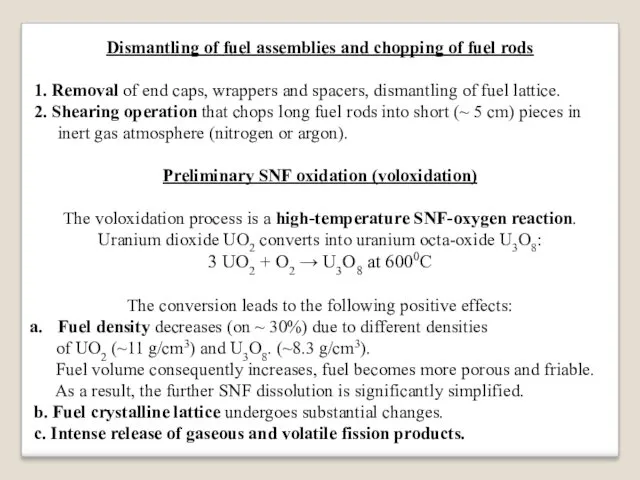
Dismantling of fuel assemblies and chopping of fuel rods
1. Removal of
end caps, wrappers and spacers, dismantling of fuel lattice.
2. Shearing operation that chops long fuel rods into short (~ 5 cm) pieces in inert gas atmosphere (nitrogen or argon).
Preliminary SNF oxidation (voloxidation)
The voloxidation process is a high-temperature SNF-oxygen reaction.
Uranium dioxide UO2 converts into uranium octa-oxide U3O8:
3 UO2 + O2 → U3O8 at 6000С
The conversion leads to the following positive effects:
Fuel density decreases (on ~ 30%) due to different densities
of UO2 (~11 g/cm3) and U3O8. (~8.3 g/cm3).
Fuel volume consequently increases, fuel becomes more porous and friable.
As a result, the further SNF dissolution is significantly simplified.
b. Fuel crystalline lattice undergoes substantial changes.
c. Intense release of gaseous and volatile fission products.
Слайд 77
SNF dissolution
SNF pieces are dissolved by boiling nitric acid HNO3:
UO2 +
HNO3 → UO2(NO3)2 + NOX + H2O.
Metal claddings of fuel rods remain undissolved.
They are removed and treated later as solid radioactive wastes.
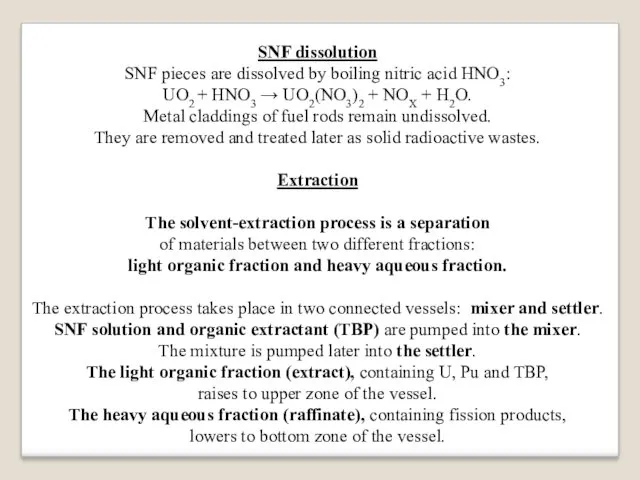
Extraction
The solvent-extraction process is a separation
of materials between two different fractions:
light organic fraction and heavy aqueous fraction.
The extraction process takes place in two connected vessels: mixer and settler.
SNF solution and organic extractant (TBP) are pumped into the mixer.
The mixture is pumped later into the settler.
The light organic fraction (extract), containing U, Pu and TBP,
raises to upper zone of the vessel.
The heavy aqueous fraction (raffinate), containing fission products,
lowers to bottom zone of the vessel.
Слайд 78
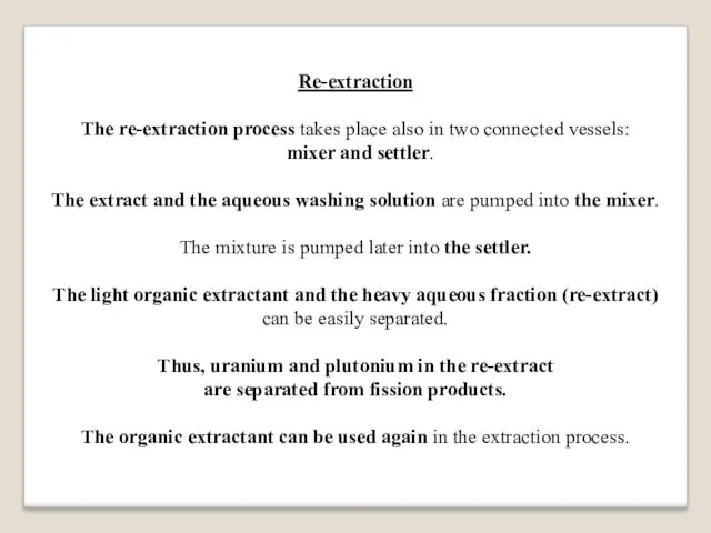
Re-extraction
The re-extraction process takes place also in two connected vessels:
mixer
and settler.
The extract and the aqueous washing solution are pumped into the mixer.
The mixture is pumped later into the settler.
The light organic extractant and the heavy aqueous fraction (re-extract) can be easily separated.
Thus, uranium and plutonium in the re-extract
are separated from fission products.
The organic extractant can be used again in the extraction process.
Слайд 79
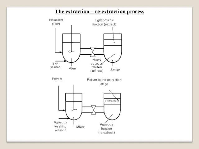
The extraction – re-extraction process
Слайд 80
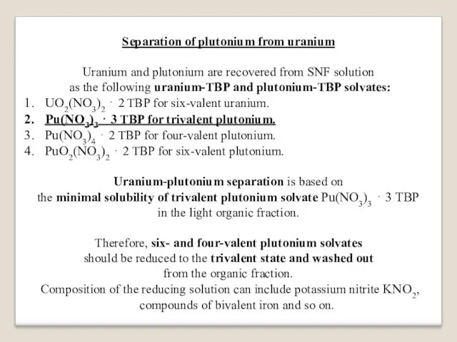
Separation of plutonium from uranium
Uranium and plutonium are recovered from SNF
solution
as the following uranium-TBP and plutonium-TBP solvates:
UO2(NO3)2 ⋅ 2 TBP for six-valent uranium.
Pu(NO3)3 ⋅ 3 TBP for trivalent plutonium.
Pu(NO3)4 ⋅ 2 TBP for four-valent plutonium.
PuO2(NO3)2 ⋅ 2 TBP for six-valent plutonium.
Uranium-plutonium separation is based on
the minimal solubility of trivalent plutonium solvate Pu(NO3)3 ⋅ 3 TBP
in the light organic fraction.
Therefore, six- and four-valent plutonium solvates
should be reduced to the trivalent state and washed out
from the organic fraction.
Composition of the reducing solution can include potassium nitrite KNO2, compounds of bivalent iron and so on.
Слайд 81
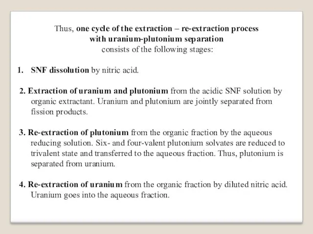
Thus, one cycle of the extraction – re-extraction process
with uranium-plutonium separation
consists of the following stages:
SNF dissolution by nitric acid.
2. Extraction of uranium and plutonium from the acidic SNF solution by organic extractant. Uranium and plutonium are jointly separated from fission products.
3. Re-extraction of plutonium from the organic fraction by the aqueous reducing solution. Six- and four-valent plutonium solvates are reduced to trivalent state and transferred to the aqueous fraction. Thus, plutonium is separated from uranium.
4. Re-extraction of uranium from the organic fraction by diluted nitric acid. Uranium goes into the aqueous fraction.
Слайд 82
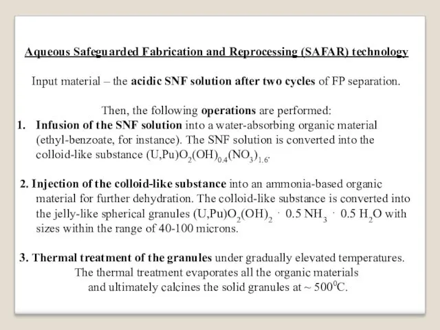
Aqueous Safeguarded Fabrication and Reprocessing (SAFAR) technology
Input material – the acidic
SNF solution after two cycles of FP separation.
Then, the following operations are performed:
Infusion of the SNF solution into a water-absorbing organic material (ethyl-benzoate, for instance). The SNF solution is converted into the colloid-like substance (U,Pu)O2(OH)0.4(NO3)1.6.
2. Injection of the colloid-like substance into an ammonia-based organic material for further dehydration. The colloid-like substance is converted into the jelly-like spherical granules (U,Pu)O2(OH)2 ⋅ 0.5 NH3 ⋅ 0.5 H2O with sizes within the range of 40-100 microns.
3. Thermal treatment of the granules under gradually elevated temperatures.
The thermal treatment evaporates all the organic materials
and ultimately calcines the solid granules at ~ 5000С.
Слайд 83
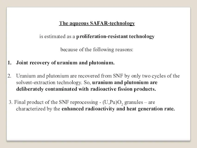
The aqueous SAFAR-technology
is estimated as a proliferation-resistant technology
because of the following
reasons:
Joint recovery of uranium and plutonium.
Uranium and plutonium are recovered from SNF by only two cycles of the solvent-extraction technology. So, uranium and plutonium are deliberately contaminated with radioactive fission products.
3. Final product of the SNF reprocessing - (U,Pu)O2 granules – are characterized by the enhanced radioactivity and heat generation rate.
Слайд 84
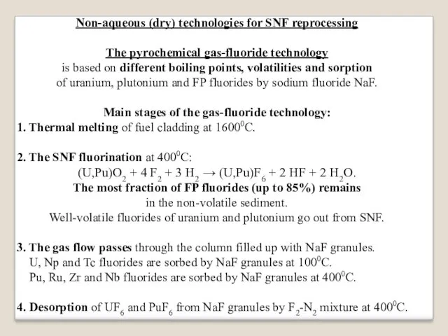
Non-aqueous (dry) technologies for SNF reprocessing
The pyrochemical gas-fluoride technology
is based on
different boiling points, volatilities and sorption
of uranium, plutonium and FP fluorides by sodium fluoride NaF.
Main stages of the gas-fluoride technology:
1. Thermal melting of fuel cladding at 16000С.
2. The SNF fluorination at 4000С:
(U,Pu)O2 + 4 F2 + 3 H2 → (U,Pu)F6 + 2 HF + 2 H2O.
The most fraction of FP fluorides (up to 85%) remains
in the non-volatile sediment.
Well-volatile fluorides of uranium and plutonium go out from SNF.
3. The gas flow passes through the column filled up with NaF granules.
U, Np and Tc fluorides are sorbed by NaF granules at 1000C.
Pu, Ru, Zr and Nb fluorides are sorbed by NaF granules at 4000C.
4. Desorption of UF6 and PuF6 from NaF granules by F2-N2 mixture at 4000С.
Слайд 85
Non-aqueous (dry) technologies for SNF reprocessing
The pyrometallurgical technology
of the electrochemical refining
is
based on different transport properties of uranium, plutonium and FP when electric current passes through the molten salts.
The electrochemical refining vessel
is filled up with liquid cadmium in the bottom part
and with molten salts
(mixture of K, Na, Ca and Ba chlorides)
above the cadmium layer.
Iron rod is introduced into the molten salts from the vessel top.
Слайд 86
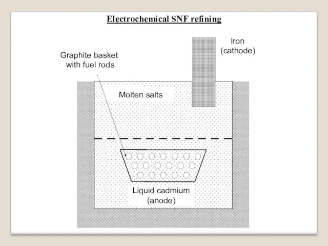
Electrochemical SNF refining
Graphite basket
with fuel rods
Liquid cadmium
(anode)
Molten salts
Iron
(cathode)
Слайд 87
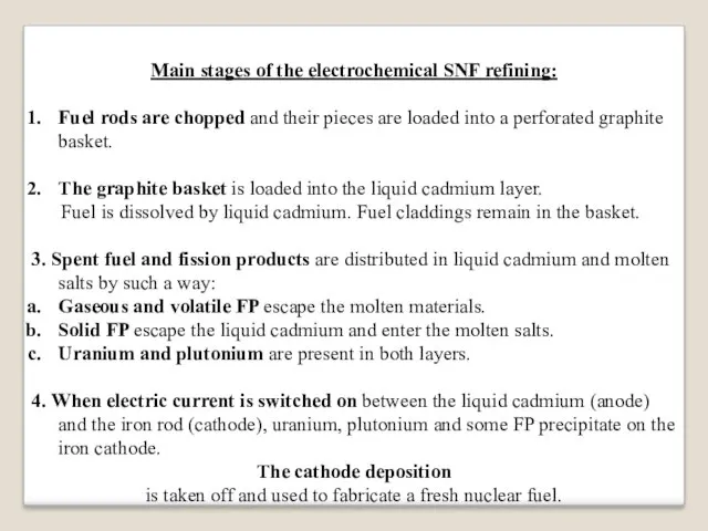
Main stages of the electrochemical SNF refining:
Fuel rods are chopped and
their pieces are loaded into a perforated graphite basket.
The graphite basket is loaded into the liquid cadmium layer.
Fuel is dissolved by liquid cadmium. Fuel claddings remain in the basket.
3. Spent fuel and fission products are distributed in liquid cadmium and molten salts by such a way:
Gaseous and volatile FP escape the molten materials.
Solid FP escape the liquid cadmium and enter the molten salts.
Uranium and plutonium are present in both layers.
4. When electric current is switched on between the liquid cadmium (anode) and the iron rod (cathode), uranium, plutonium and some FP precipitate on the iron cathode.
The cathode deposition
is taken off and used to fabricate a fresh nuclear fuel.
Слайд 88
DUPIC-technology
(DUPIC means Direct Use of spent PWR fuel in CANDU)
The
SNF discharged from light-water PWR-type reactors
can be used in heavy-water CANDU-type reactors
because spent PWR fuel contains large enough amount of fissile isotopes:
residual uranium enrichment ~ 0.9% 235U,
~ 0.7% of reactor-grade plutonium
(about 70% of fissile isotopes 239Pu and 241Pu).
Total content of fissile isotopes in spent PWR fuel is about 1.4%.
CANDU reactors can be fuelled even with natural uranium (0.7% 235U).
The two-fold content of fissile isotopes in spent PWR fuel
makes operation of CANDU reactors feasible.
The DUPIC-technology provides spent PWR fuel reprocessing
with application of thermal and mechanical procedures only.
Слайд 89
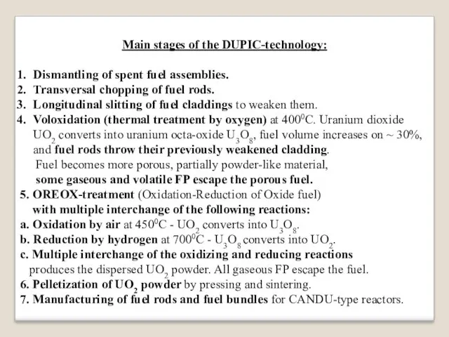
Main stages of the DUPIC-technology:
Dismantling of spent fuel assemblies.
Transversal chopping of
fuel rods.
Longitudinal slitting of fuel claddings to weaken them.
Voloxidation (thermal treatment by oxygen) at 4000С. Uranium dioxide UO2 converts into uranium octa-oxide U3O8, fuel volume increases on ~ 30%, and fuel rods throw their previously weakened cladding.
Fuel becomes more porous, partially powder-like material,
some gaseous and volatile FP escape the porous fuel.
5. OREOX-treatment (Oxidation-Reduction of Oxide fuel)
with multiple interchange of the following reactions:
a. Oxidation by air at 4500С - UO2 converts into U3O8.
b. Reduction by hydrogen at 7000С - U3O8 converts into UO2.
c. Multiple interchange of the oxidizing and reducing reactions
produces the dispersed UO2 powder. All gaseous FP escape the fuel.
6. Pelletization of UO2 powder by pressing and sintering.
7. Manufacturing of fuel rods and fuel bundles for CANDU-type reactors.
Слайд 90
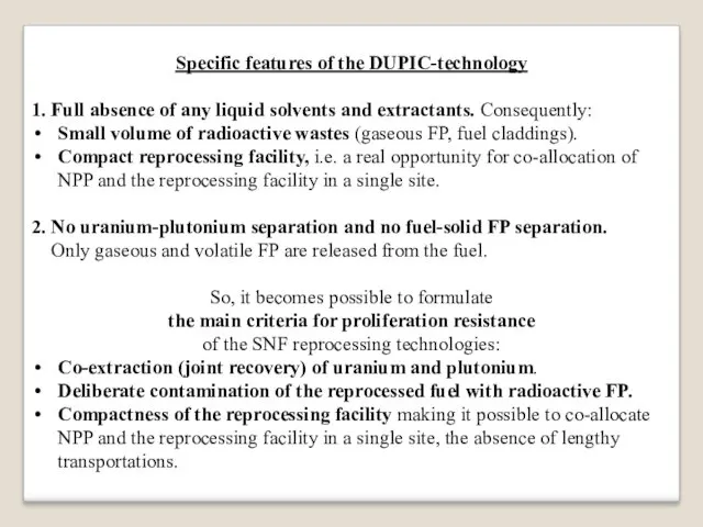
Specific features of the DUPIC-technology
1. Full absence of any liquid solvents
and extractants. Consequently:
Small volume of radioactive wastes (gaseous FP, fuel claddings).
Compact reprocessing facility, i.e. a real opportunity for co-allocation of NPP and the reprocessing facility in a single site.
2. No uranium-plutonium separation and no fuel-solid FP separation.
Only gaseous and volatile FP are released from the fuel.
So, it becomes possible to formulate
the main criteria for proliferation resistance
of the SNF reprocessing technologies:
Co-extraction (joint recovery) of uranium and plutonium.
Deliberate contamination of the reprocessed fuel with radioactive FP.
Compactness of the reprocessing facility making it possible to co-allocate NPP and the reprocessing facility in a single site, the absence of lengthy transportations.
Слайд 91
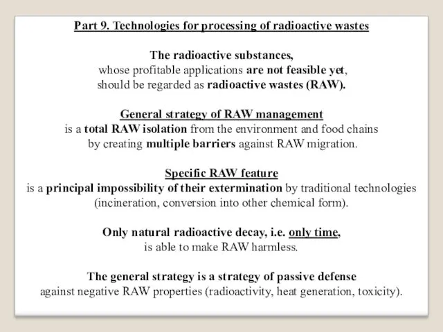
Part 9. Technologies for processing of radioactive wastes
The radioactive substances,
whose
profitable applications are not feasible yet,
should be regarded as radioactive wastes (RAW).
General strategy of RAW management
is a total RAW isolation from the environment and food chains
by creating multiple barriers against RAW migration.
Specific RAW feature
is a principal impossibility of their extermination by traditional technologies
(incineration, conversion into other chemical form).
Only natural radioactive decay, i.e. only time,
is able to make RAW harmless.
The general strategy is a strategy of passive defense
against negative RAW properties (radioactivity, heat generation, toxicity).
Слайд 92
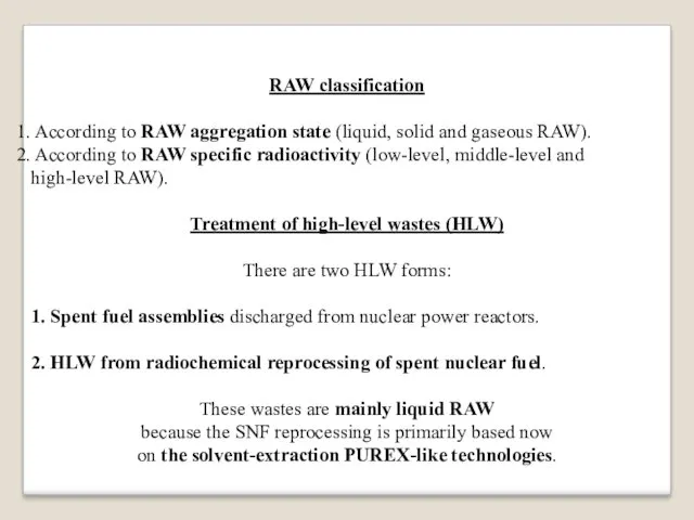
RAW classification
According to RAW aggregation state (liquid, solid and gaseous
RAW).
According to RAW specific radioactivity (low-level, middle-level and high-level RAW).
Treatment of high-level wastes (HLW)
There are two HLW forms:
1. Spent fuel assemblies discharged from nuclear power reactors.
2. HLW from radiochemical reprocessing of spent nuclear fuel.
These wastes are mainly liquid RAW
because the SNF reprocessing is primarily based now
on the solvent-extraction PUREX-like technologies.
Слайд 93
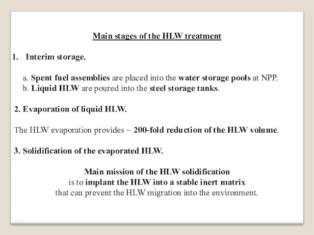
Main stages of the HLW treatment
Interim storage.
a. Spent fuel assemblies
are placed into the water storage pools at NPP.
b. Liquid HLW are poured into the steel storage tanks.
2. Evaporation of liquid HLW.
The HLW evaporation provides ~ 200-fold reduction of the HLW volume.
3. Solidification of the evaporated HLW.
Main mission of the HLW solidification
is to implant the HLW into a stable inert matrix
that can prevent the HLW migration into the environment.
Слайд 94
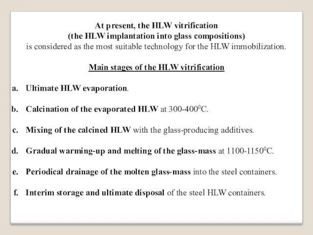
At present, the HLW vitrification
(the HLW implantation into glass compositions)
is considered
as the most suitable technology for the HLW immobilization.
Main stages of the HLW vitrification
Ultimate HLW evaporation.
Calcination of the evaporated HLW at 300-4000C.
Mixing of the calcined HLW with the glass-producing additives.
Gradual warming-up and melting of the glass-mass at 1100-11500С.
Periodical drainage of the molten glass-mass into the steel containers.
Interim storage and ultimate disposal of the steel HLW containers.
Слайд 95
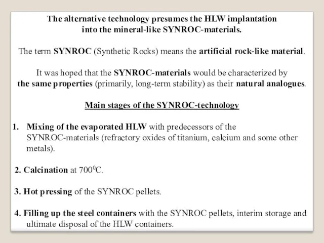
The alternative technology presumes the HLW implantation
into the mineral-like SYNROC-materials.
The term
SYNROC (Synthetic Rocks) means the artificial rock-like material.
It was hoped that the SYNROC-materials would be characterized by
the same properties (primarily, long-term stability) as their natural analogues.
Main stages of the SYNROC-technology
Mixing of the evaporated HLW with predecessors of the SYNROC-materials (refractory oxides of titanium, calcium and some other metals).
2. Calcination at 7000С.
3. Hot pressing of the SYNROC pellets.
4. Filling up the steel containers with the SYNROC pellets, interim storage and ultimate disposal of the HLW containers.
Слайд 96
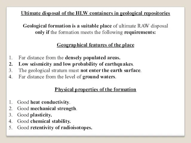
Ultimate disposal of the HLW containers in geological repositories
Geological formation is
a suitable place of ultimate RAW disposal
only if the formation meets the following requirements:
Geographical features of the place
Far distance from the densely populated areas.
Low seismicity and low probability of earthquakes.
The geological stratum must not enter the earth surface.
Far distance from the level of ground waters.
Physical properties of the formation
Good heat conductivity.
Good mechanical strength.
Good plasticity.
Good chemical stability.
Good retentivity of radioisotopes.
Слайд 97
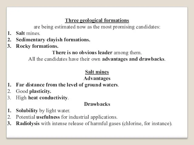
Three geological formations
are being estimated now as the most promising candidates:
Salt
mines.
Sedimentary clayish formations.
Rocky formations.
There is no obvious leader among them.
All the candidates have their own advantages and drawbacks.
Salt mines
Advantages
Far distance from the level of ground waters.
Good plasticity.
High heat conductivity.
Drawbacks
Solubility by light water.
Potential usefulness for industrial applications.
Radiolysis with intense release of harmful gases (chlorine, for instance).
Слайд 98
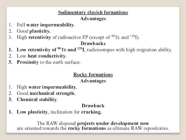
Sedimentary clayish formations
Advantages
Full water impermeability.
Good plasticity.
High retentivity of radioactive FP (except
of 99Tc and 129I).
Drawbacks
Low retentivity of 99Tc and 129I, radioisotopes with high migration ability.
Low heat conductivity.
Proximity to the earth surface.
Rocky formations
Advantages
High water impermeability.
Good mechanical strength.
Chemical stability.
Drawback
Low plasticity, inclination for cracking.
The RAW disposal projects under development now
are oriented towards the rocky formations as ultimate RAW repositories.
Слайд 99
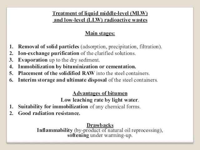
Treatment of liquid middle-level (MLW)
and low-level (LLW) radioactive wastes
Main stages:
Removal
of solid particles (adsorption, precipitation, filtration).
Ion-exchange purification of the clarified solutions.
Evaporation up to the dry sediment.
Immobilization by bituminization or cementation.
Placement of the solidified RAW into the steel containers.
Interim storage and ultimate disposal of the steel containers.
Advantages of bitumen
Low leaching rate by light water.
Suitability for immobilization of any chemical forms.
Good radiation resistance.
Drawbacks
Inflammability (by-product of natural oil reprocessing),
softening under warming-up.
Слайд 100

Alternative option for the RAW bituminization is a cementation,
i.e. the RAW
implantation into the concrete blocks
Advantages
Low cost and simplicity of the cementation process.
Good radiation resistance.
High heat conductivity.
4. Concrete is not an inflammable material
and shows no softening under warming-up.
However, concrete is very sensitive to the water leaching.
Comparative data
on the water leaching rate
1. Glass - 10-8 ÷ 10-7 g/(cm2⋅day).
2. SYNROC - 10-6 ÷ 10-5 g/(cm2⋅day).
3. Bitumen - 10-6 ÷ 10-4 g/(cm2⋅day).
4. Concrete - 10-3 ÷ 10-2 g/(cm2⋅day).
Glass and SYNROC-materials are used for the HLW immobilization
while bitumen and concrete are used for the MLW and LLW immobilization.
Слайд 101
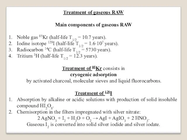
Treatment of gaseous RAW
Main components of gaseous RAW
Noble gas 85Kr (half-life
T1/2 = 10.7 years).
Iodine isotope 129I (half-life T1/2 = 1.6∙107 years).
Radiocarbon 14C (half-life T1/2 = 5730 years).
Tritium 3H (half-life T1/2 = 12.3 years).
Treatment of 85Kr consists in
cryogenic adsorption
by activated charcoal, molecular sieves and liquid fluorocarbons.
Treatment of 129I
Absorption by alkaline or acidic solutions with production of solid insoluble compound HI2O8.
Chemisorption in the filters impregnated with silver nitrate:
2 AgNO3 + I2 + H2O + O2 → AgI + AgIO3 + 2 HNO3.
Gaseous I2 is converted into solid silver iodide and silver iodate.
Слайд 102
Treatment of gaseous RAW
Treatment of 14C
Radiocarbon is a product of 14N(n,p)14C
reaction.
Nitrogen is an impurity in coolant and structural materials.
Till now, no effective technology for capture radiocarbon oxides
has been developed yet.
Some liquid fluorocarbons demonstrated efficient absorption of 14C
within low temperature range (from -400C up to +40C)
Treatment of tritium 3H
Tritium is a product of neutron reactions with hydrogen in coolant
and lithium in structural materials as an impurity.
During SNF voloxidation, humid air can bind tritium into tritium water T2O for further treatment as a component of liquid RAW.
Light-water washing-out of organic fraction after the solvent-extraction.
Chemisorption of tritium water by zeolite (porous mineral).
Слайд 103

Treatment of solid RAW
Main components of solid RAW
Details of nuclear equipment,
structural materials, rubbish, work clothes, etc.
Ion-exchange resins and filters.
Metal claddings of fuel rods.
Deposits on inner surfaces of technological equipment (pipes, vessels, etc).
Methods for treatment of solid RAW
(the first two categories)
1. Reduction of RAW volume:
a. Incineration with up to 100-fold reduction of RAW volume.
b. Pressing with up to 10-fold reduction of RAW volume.
2. Placement of the treated RAW into the steel containers, interim storage and ultimate disposal.
Слайд 104
Treatment of fuel claddings
1. Chemical treatment by hydrofluoric acid HF at
6000C. The treatment results in the formation of superficial friable films on the cladding surface.
2. Dissolution and removal of the films by alkaline or acidic solutions.
3. Melting of fuel claddings into metal ingots in electrical furnaces.
4. Placement of the metal ingots into the steel containers, interim storage and ultimate disposal.
Treatment of inner radioactive deposits
The radioactive deposits on inner surfaces of technological equipment
can be formed by the following processes:
1. Sorption from the SNF solutions.
2. Gradual saturation of the deposits with radioisotopes.
3. Gradual hardening of the deposits under rigid radiation, thermal, physical and chemical conditions of the SNF reprocessing.
Слайд 105
Main decontamination technology – the RAW desorption
Desorption of radioactive deposits converts
the solid RAW into liquid form.
The multi-stage washing-out process is performed:
At first, low concentrated solution of nitric acid HNO3 is used
to dissolve and remove the SNF residuals.
2. Multiple alternation of the wall treatment by liquid desorbing solutions
is used to weaken, dissolve and remove the deposits.
Washing-out by alkaline solutions (chemical dissociation and loosening
of the deposits).
Washing-out by acidic solutions (dissolution and removal
of the friable deposits).
Multiple alternation of the washing-out procedures
can completely clean the inner surfaces from radioactive deposits.

 Уравнение теплового баланса
 Радиотехническая отрасль, ее состав и значение для развития современного общества. Системы радиосвязи и радиовещания
 Изменение агрегатных состояний вещества. 8 класс
 Введение в динамику. Законы и аксиомы динамики материальной точки. Основное уравнение динамики
 Открытый урок с использованием ЭОР по теме Влажность воздуха
 Предпосылки создания ракет большой дальности. Зарождение ракетной техники
 Самостоятельная робота на уроках физики
 Электромагнитное поле
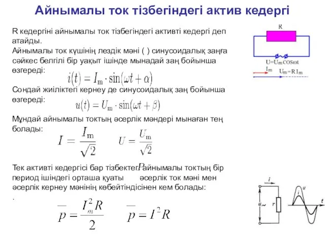 Айнымалы ток тізбегіндегі актив кедергі. (Лекция 14)
 Сила тока. Единицы силы тока. Амперметр. Измерение силы тока
 Электрический ток в полупроводниках
 Линзы
Линзы Затухающие и вынужденные колебания. Уравнение затухающих колебаний
 Магистральный двухсекционный тепловоз 2ТЭ116
 Динамика поступательного движения. Законы сохранения
 Элементы квантовой механики. Лекция 12
 Зрение
 Взаємодія тіл. Імпульс. Закон збереження імпульсу
 Закон всемирного тяготения. Сила тяжести. Вес
 Стальные и растительные тросы
 Испарение и конденсация
 Основные понятия термодинамики
 Проводниковые материалы
 Аэродинамические весы
 атомная бомба
 Основные понятия и определения. Классификация электрических цепей
 Электризация тел. Два рода зарядов
 Електронні вольтметри