- Ball mill dynamics. Grinding

Содержание
- 2. Content Size reduction mechanism Release point and internal dynamics 1st and 2nd chamber 1st chamber liners
- 3. Content Size reduction mechanism Release point and internal dynamics 1st and 2nd chamber 1st chamber liners
- 4. 3 mechanisms of size reduction Fractures Crushing Chipping Crushing and some fines Abrasion Fine grinding
- 5. Internal ball dynamics Cataracting Free fall of the balls Emphasis on crushing Cascading Tumbles along charge
- 6. Content Size reduction mechanism Release point and internal dynamics 1st and 2nd chamber 1st chamber liners
- 7. Release points and grinding Position depends on three main factors % of critical speed Liner’s design
- 8. Release point and mill critical speed Speed of rotation at which centrifugal forces overcome gravity forces
- 9. Release points and liners design Different liners design can give different release points and therefore different
- 10. Internal dynamics in first chamber Primary grinding of coarse material with large grinding media (Ø 90-60
- 11. Internal dynamics in second chamber Development of a high fineness with small grinding media (Ø 50-15
- 12. Content Size reduction mechanism Release point and internal dynamics 1st and 2nd chamber 1st chamber liners
- 13. Purpose of a liner’s design Each liner is designed to ensure: Lowest specific energy consumption Highest
- 15. Activator liners Step liner Wave liner type “Duolift” Step liner tpe “Xlift” Step liner with wave
- 16. Step liner Only for first compartments Better wear characteristics Moderate lift Designed for DIN drilled shell
- 17. Single wave & Duolift liners Only for first compartments Single wave Negative back slope induces sliding
- 18. Installed Duolift liners
- 19. First chamber - Reminders Be careful of the appropriate ratio between Critical speed Liner lifting action
- 20. Content Size reduction mechanism Release point and internal dynamics 1st and 2nd chamber 1st chamber liners
- 21. Second chamber liners Classifying lining with activator profile Conventional classifying lining with wave profile Wave lining
- 22. Purpose of classifying liners Match ball size to particle size (Bond Formula) without partitions
- 23. Examples of classifying liners
- 24. Classifying liners - issues Causes of poor classification Liner’s step wear Lifting of the charge too
- 25. Classifying liner design and mill shell size
- 26. Other types of liners : grooved liners
- 27. Other types of liners : Danula or Dam Rings Where we find it Long mills, in
- 28. Second chamber - Reminders Classifying liners Causes for poor classification Liner step wear Lifting of the
- 29. Liner material selection: Breakage resistance Wear resistance LOW CHROMIUM ALLOY 3% Cr 0,5% C 45-50 HRC
- 30. Content Size reduction mechanism Release point and internal dynamics 1st and 2nd chamber 1st chamber liners
- 31. Fastening types Bolted Requires a drilling in the mill tube for every plate Easy handling during
- 32. Semi-bolted Minimum two bolted rows in total Requires special tools and experienced fitters Fastening types
- 33. Fastening types Boltless Plates are forced-fitted with positive locking without any bolts Requires precise preparation, special
- 34. Liners’ wear management Liner wear optimisation Avoid metal / metal contact Minimise purge duration Look for
- 35. Content Size reduction mechanism Release point and internal dynamics 1st and 2nd chamber 1st chamber liners
- 36. Balls wear
- 37. Content Size reduction mechanism Release point and internal dynamics 1st and 2nd chamber 1st chamber liners
- 38. Mill head lining Conical design Conical head lining plates on a conical mill head are exposed
- 39. Mill head lining Straight design (with structure) Straight head lining plates on a conical mill head
- 40. Content Size reduction mechanism Release point and internal dynamics 1st and 2nd chamber 1st chamber liners
- 41. Mass transport Reason for mass transport in the mill shell Mill inlet feed pushes the material
- 42. Material filling ratio Definition (In practice, it is evaluated with the level of material above or
- 43. Grinding vs. filling Interparticle grinding occurs when the voids space is properly filled The collision of
- 44. Mill bypass Ball charge expands when overloaded In the extreme, a stream of material “bypass” the
- 46. Скачать презентацию
 Изобретение радио А.С. Поповым
 Конденсаторы
 Фотолитография. Практическое занятие 4
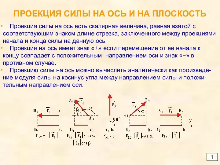 Проекция силы на ось и на плоскость
 Мастер-класс по теме Использование системно-деятельностного подхода для повышения качества на уроках физики
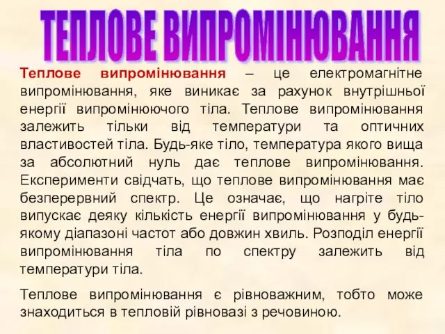 Теплове випромінювання
 История возникновения спектроскопии
 Звуковые волны. Скорость звука.
 Термодинамика. Изменение агрегатных состояний вещества
 История изобретения велосипеда. 2 класс
 Естественное и искусственное освещение
 Прилади спін-хвильової електроніки
 Кинематические схемы
 Самоанализ учителя физики
 Эксперимент – как метод активизации мыслительной деятельности учащихся на уроках физики
 MATLAB 程式設計入門篇 音訊讀寫、錄製與播放
 Timing recovery in baseband transmission. (Lecture 8)
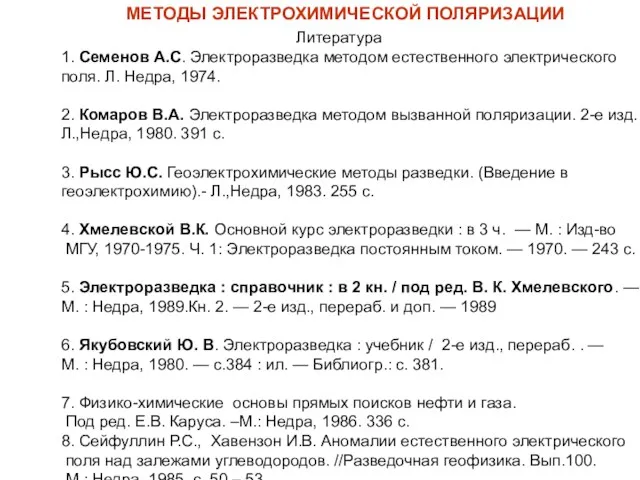 Методы электрохимической поляризации
 Ферродинамические приборы
 Жидкостная система охлаждения. Урок № 32
 Проявление сил в живой природе
 Производственно-техническая база предприятий автосервиса (Лекция № 5)
 Сила трения. Трение в природе и технике. 9 класс
 Проект производственного участка по ТО и ремонту приборов системы питания автомобилей с дизельными двигателями
 Классический метод расчета переходных процессов. Переходные процессы в цепях с r и L, r и C при постоянных напряжениях. Лекция 8
 ФИЗИКА 8 класс Изменение агрегатных состояний вещества
 Виртуальный музей радиосвязи
 Электронный парамагнитный резонанс