- Electric field. General information

Содержание
- 2. Outline Systems of Units; Electric Circuits and Current; Voltage; Power and Energy; Literature; Q&A;
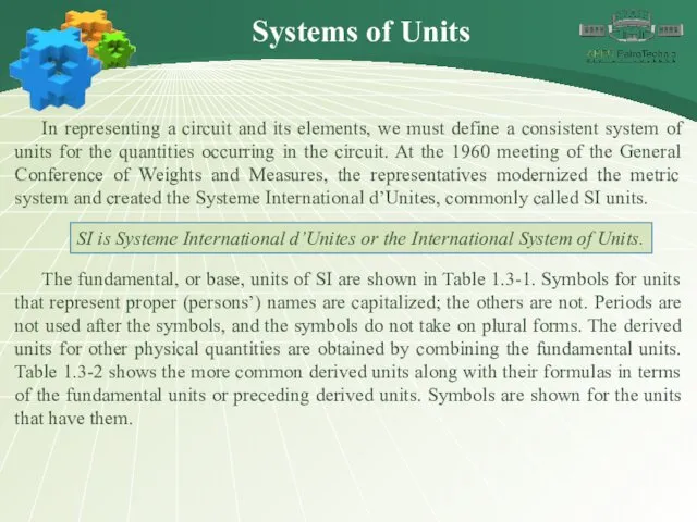
- 3. Systems of Units In representing a circuit and its elements, we must define a consistent system
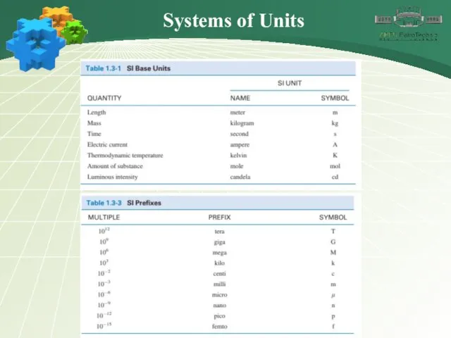
- 4. Systems of Units
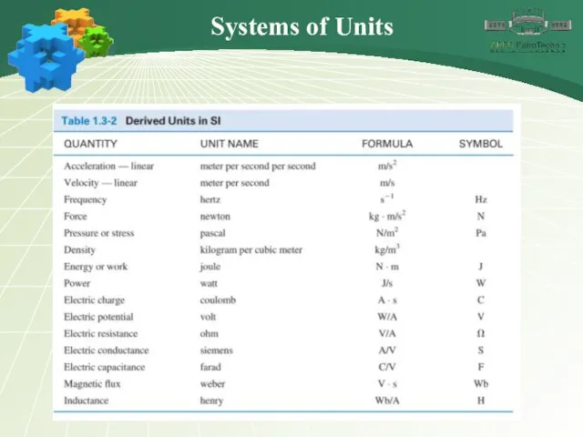
- 5. Systems of Units
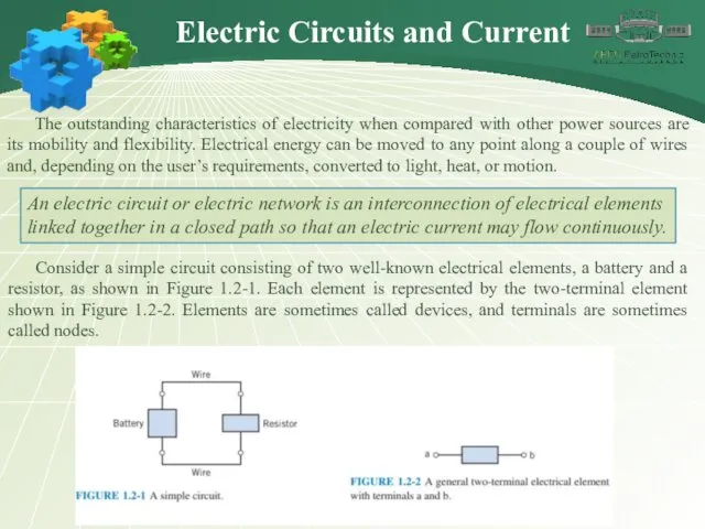
- 6. Electric Circuits and Current The outstanding characteristics of electricity when compared with other power sources are
- 7. Charge may flow in an electric circuit. Current is the time rate of change of charge
- 8. Figure 1.2-3 shows the notation that we use to describe a current. There are two parts
- 9. We always associate an arrow with a current to denote its direction. A complete description of
- 10. A time-varying current i(t) can take many forms, such as a ramp, a sinusoid, or an
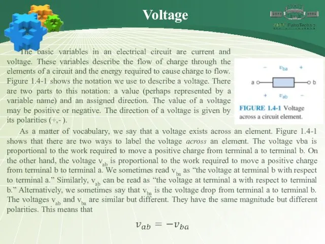
- 11. Voltage The basic variables in an electrical circuit are current and voltage. These variables describe the
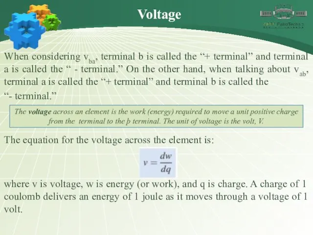
- 12. Voltage When considering vba, terminal b is called the “+ terminal” and terminal a is called
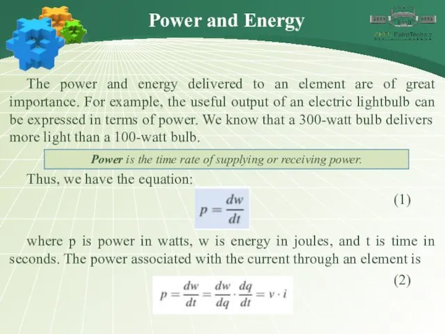
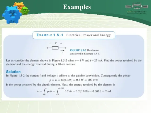
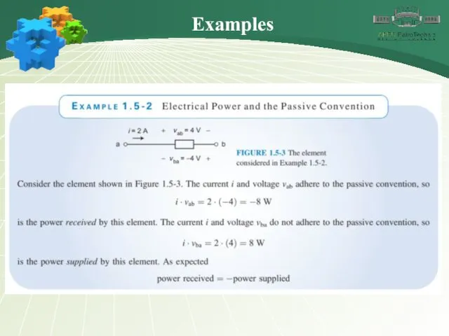
- 13. Power and Energy The power and energy delivered to an element are of great importance. For
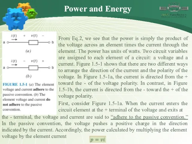
- 14. From Eq.2, we see that the power is simply the product of the voltage across an
- 15. is the power received by the element. (This power is sometimes called “the power absorbed by
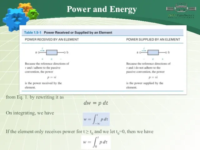
- 16. Power and Energy from Eq. 1. by rewriting it as On integrating, we have If the
- 17. Literature
- 18. THANK YOU !
- 19. Do you have any questions?
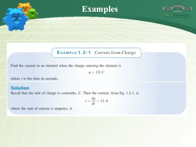
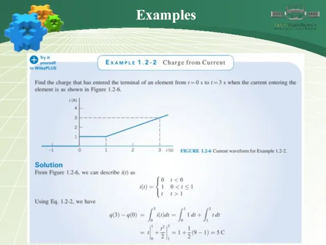
- 20. Examples
- 21. Examples
- 22. Examples
- 23. Examples
- 25. Скачать презентацию
Outline
Systems of Units;
Electric Circuits and Current;
Voltage;
Power and Energy;
Literature;
Q&A;
Outline
Systems of Units;
Electric Circuits and Current;
Voltage;
Power and Energy;
Literature;
Q&A;
Systems of Units
In representing a circuit and its elements, we must
Systems of Units
In representing a circuit and its elements, we must
Systems of Units
Systems of Units
Systems of Units
Systems of Units
Electric Circuits and Current
The outstanding characteristics of electricity when compared with
Electric Circuits and Current
The outstanding characteristics of electricity when compared with
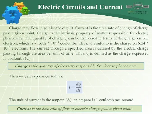
Charge may flow in an electric circuit. Current is the time
Charge may flow in an electric circuit. Current is the time
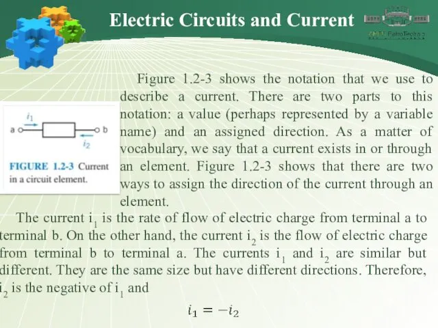
Figure 1.2-3 shows the notation that we use to describe a
Figure 1.2-3 shows the notation that we use to describe a
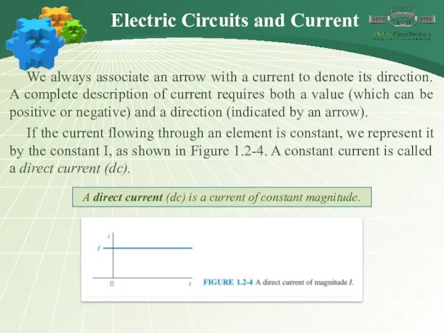
We always associate an arrow with a current to denote its
We always associate an arrow with a current to denote its
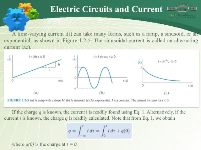
A time-varying current i(t) can take many forms, such as a
A time-varying current i(t) can take many forms, such as a
Voltage
The basic variables in an electrical circuit are current and voltage.
Voltage
The basic variables in an electrical circuit are current and voltage.
Voltage
When considering vba, terminal b is called the “+ terminal” and
Voltage
When considering vba, terminal b is called the “+ terminal” and
Power and Energy
The power and energy delivered to an element are
Power and Energy
The power and energy delivered to an element are
From Eq.2, we see that the power is simply the product
From Eq.2, we see that the power is simply the product
is the power received by the element. (This power is sometimes
is the power received by the element. (This power is sometimes
Power and Energy
from Eq. 1. by rewriting it as
On integrating, we
Power and Energy
from Eq. 1. by rewriting it as
On integrating, we
Literature
Literature
THANK YOU !
THANK YOU !
Do you have any questions?
Do you have any questions?
Examples
Examples
Examples
Examples
Examples
Examples
Examples
Examples
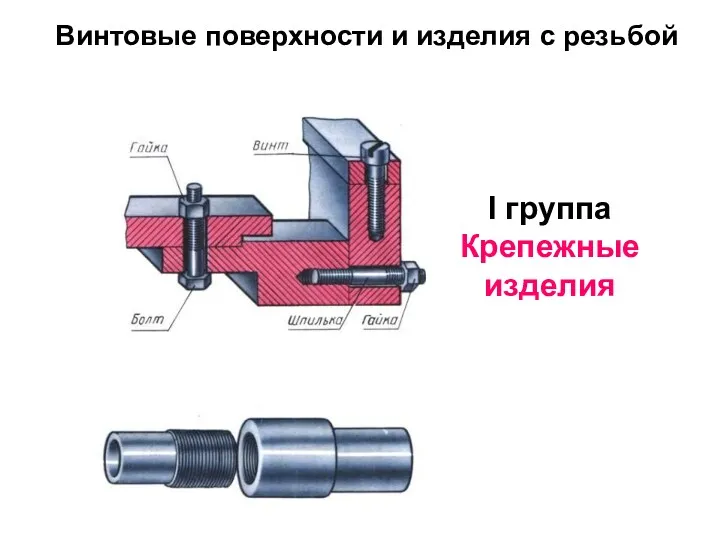 Винтовые поверхности и изделия с резьбой. Крепежные изделия
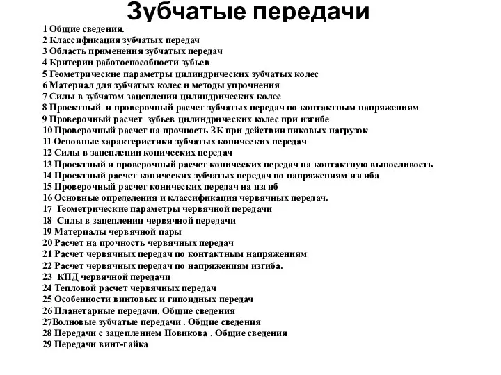 Зубчатые передачи
 Моменты импульса (угловые моменты). Часть вторая
 Градуировка спектроскопа
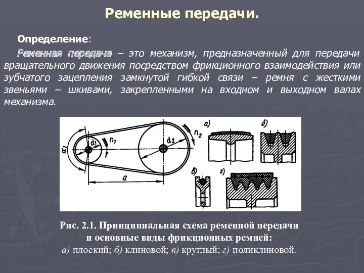 Ременные передачи
 Количество теплоты
 Источники оптического импульсного когерентного излучения для информационных систем II. Полупроводниковые лазеры
 Разработка лаборатории по ремонту и диагностики топливных систем дизельных двигателей
 Техническое диагностирование автомобильной техники
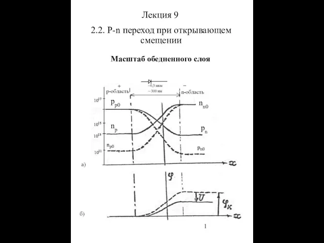 P-n переход при открывающем смещении. Масштаб обедненного слоя
 Тепломассообмен. Конвекция
 Кинематика материальной точки. Физические модели
 Основы физической реабилитации
 Физические и геологические основы сейсморазведки
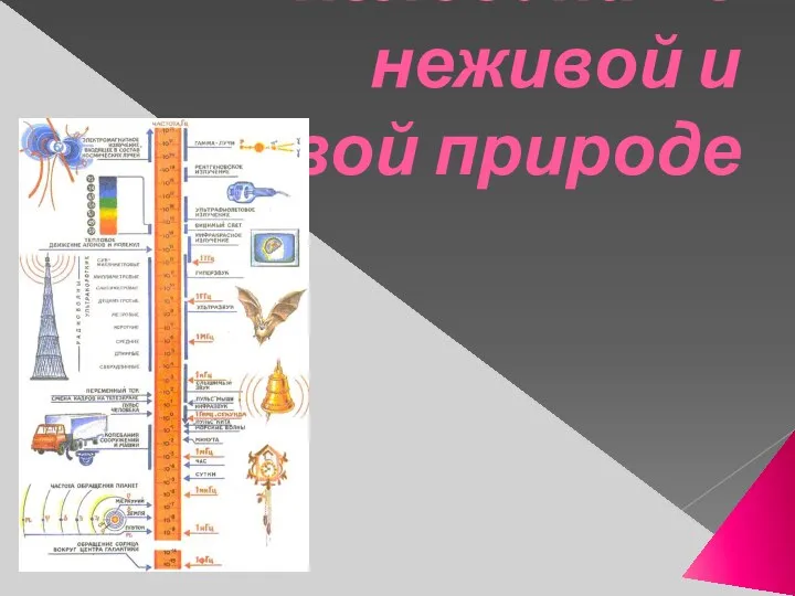 Колебания в неживой и живой природе. Урок 11
 Презентация. Законы Ньютона
 Презентация по теме Механические колебания
 Работа, кинетическая энергия
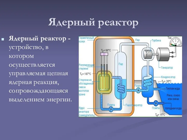 Ядерный реактор
 Проводниковые материалы
 Осесимметричные тонкостенные оболочки. Лекция 12
 Выяснение условия равновесия рычага
 Открытия М.В. Ломоносова в области физики и астрономии
 Масса вещества. Плотность
 Электрическая цепь и ее элементы
 Migrating from Streams to GoldenGate12c
 Электроразведка. Методы профилирования
 Управляемость автомобиля. Лекция № 11