- Godfrin Cryocoolers

Содержание
- 2. The course is based on: Basic operation of cryocoolers and related thermal machines A.T.A.M. de Waele
- 3. Outline of the course Introduction Some thermodynamics Joule-Thomson coolers Stirling cycle Stirling engines Stirling coolers Pulse-tube
- 4. What is a « cryo-cooler » A Cryocooler is a standalone cooler, usually of table-top size.
- 5. Laws of Thermodynamics
- 6. Open systems
- 7. First law for open systems
- 8. second law for open systems
- 9. Irreversible processes heat flow over a temperature difference mass flow over a pressure difference diffusion chemical
- 10. Heat engines first law reduces to second law reduces to
- 11. Cold source needed….
- 12. Efficiency
- 13. Refrigerators
- 14. Need external power!
- 15. Coefficient Of Performance (COP)
- 16. Dissipated power
- 17. Different types of Cryo-coolers Oscillating gas flow cryocoolers Stirling refrigerators Gifford-McMahon (GM) refrigerators Pulse-tube refrigerators Constant
- 18. Joule-Thomson coolers Invented by Carl von Linde and William Hampson, it is sometimes named after them.
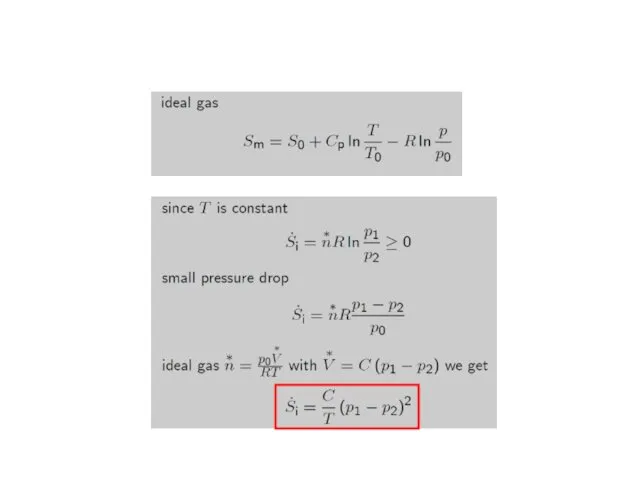
- 19. Joule-Thomson: thermodynamics
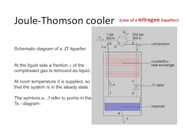
- 21. Joule-Thomson cooler Schematic diagram of a JT liquefier At the liquid side a fraction x of
- 22. Ts-diagram of nitrogen with isobars, isenthalps, and the lines of coexistence. The pressures are given in
- 23. Ts-diagram of nitrogen with isobars at 1 and 200 bar, the coexistence line and the isenthalp
- 24. Stirling cycle
- 25. Stirling cycle and Stirling engines
- 26. Stirling alpha engine https://en.wikipedia.org/wiki/Stirling_engine
- 27. Stirling beta engine https://en.wikipedia.org/wiki/Stirling_engine https://en.wikipedia.org/wiki/Stirling_engine
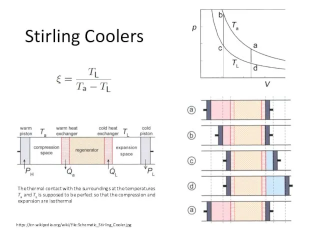
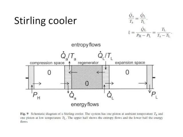
- 28. Stirling Coolers https://en.wikipedia.org/wiki/File:Schematic_Stirling_Cooler.jpg The thermal contact with the surroundings at the temperatures Ta and TL is
- 29. 1. From a to b. The warm piston moves to the right over a certain distance
- 30. Stirling cooler
- 32. Displacer-type Stirling coolers Modified Stirling cycle. The cold piston is replaced by a displacer.
- 33. PULSE-TUBE REFRIGERATORS (PTRs)
- 34. Stirling type single-orifice PTR From left to right the system consists of a compressor with moving
- 35. Some remarks… The piston moves the gas back and forth and generates a varying pressure in
- 36. Thermodynamics… with T the temperature, Cp the molar heat capacity at constant pressure, αV the volumetric
- 37. Left : a gas element enters the tube at temperature TL and leaves it at a
- 38. At the hot end gas flows from the buffer via the orifice into the tube with
- 39. Ideal regenerators The thermodynamic and hydrodynamic properties of regenerators usually are extremely complicated. In many cases
- 40. Regenerator: materials
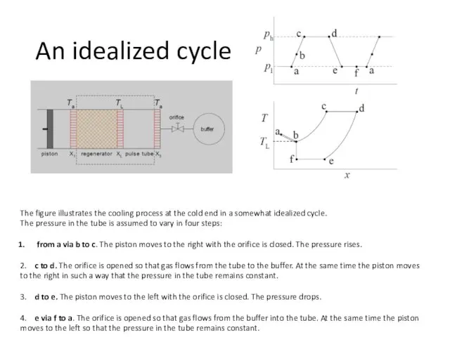
- 41. The figure illustrates the cooling process at the cold end in a somewhat idealized cycle. The
- 42. Now we follow a gas element that is inside the regenerator at the start of the
- 43. Thermodynamics of PTR’s Ideal PTR: dissipation only occurs in the orifice
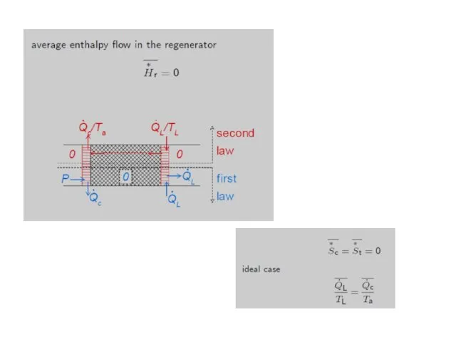
- 44. Thermodynamic systems containing the orifice (a), the heat exchanger X3 (b), the pulse tube and its
- 46. Coefficient Of Performance (COP)
- 47. Pulse-tube refrigerators have their origin in an observation that W. E. Gifford made, while working on
- 48. The PTR has no moving parts in the low-temperature region, and, therefore, has a long lifetime
- 49. The main breakthrough came in 1984, when Mikulin and his co-workers invented the Orifice Pulse Tube
- 50. PhD Thesis Low-temperature cryocooling / by Irina Tanaeva. - Eindhoven : Technische Universiteit Eindhoven, 2004. –
- 51. Low temperatures achieved by PT coolers
- 54. Additional cooling power [5] Experimental results on the free cooling power available on 4K pulse tube
- 55. Additional cooling power Experimental results on the free cooling power available on 4K pulse tube coolers
- 57. Commercial pulse-tubes
- 58. PT 10 12W @ 80K Air or Water Cooled PT 60 60W @ 80K Air or
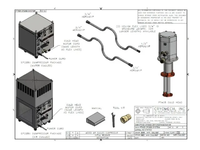
- 59. Standard 4K Cryomech Two-Stage Pulse Tube Cryorefrigerators All models have remote-motor options available PT 403 First
- 60. PT 405
- 64. Features of Pulse Tube Cryorefrigerators Long mean time between maintenance Minimal general maintenance Ideal for vibration
- 65. Liquid Helium Plants and Recovery Systems Liquefaction rates from 6-60 liters per day
- 66. Helium Reliquefiers
- 67. Sumitomo pulse-tubes Specifications
- 68. RP-062B 4K Pulse Tube Cryocooler Series http://www.shicryogenics.com/products/pulse-tube-cryocoolers/rp-062b-4k-pulse-tube-cryocooler-series/
- 69. Other manufacturers Advanced Research Systems (ARS) http://www.arscryo.com/ Thales Cryogenics http://www.thales-cryogenics.com
- 70. Gifford-McMahon (GM)-coolers Schematic diagram of a GM-cooler. Vl and Vh are buffer volumes of the compressor.
- 71. Gifford-McMahon (GM)-coolers In reality rotary valves are used
- 72. Gifford-McMahon (GM)-coolers
- 76. Скачать презентацию
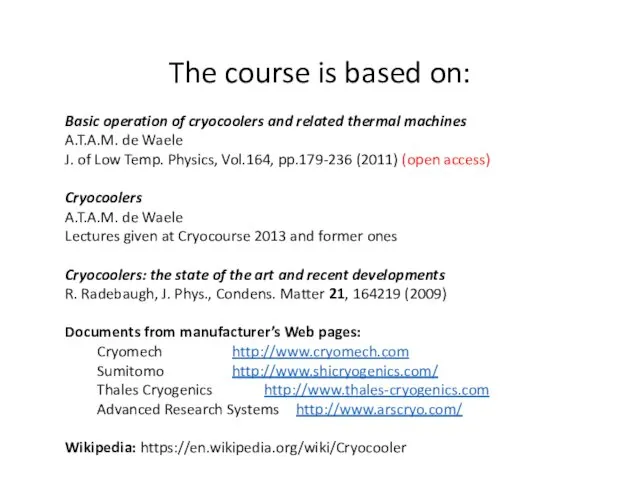
The course is based on:
Basic operation of cryocoolers and related thermal
The course is based on:
Basic operation of cryocoolers and related thermal
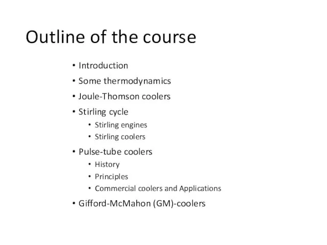
Outline of the course
Introduction
Some thermodynamics
Joule-Thomson coolers
Stirling cycle
Stirling engines
Stirling coolers
Pulse-tube coolers
History
Principles
Commercial
Outline of the course
Introduction
Some thermodynamics
Joule-Thomson coolers
Stirling cycle
Stirling engines
Stirling coolers
Pulse-tube coolers
History
Principles
Commercial
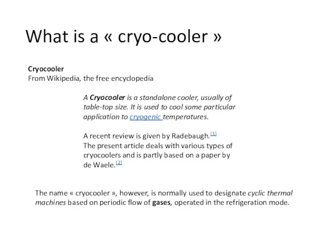
What is a « cryo-cooler »
A Cryocooler is a standalone cooler, usually of
What is a « cryo-cooler »
A Cryocooler is a standalone cooler, usually of
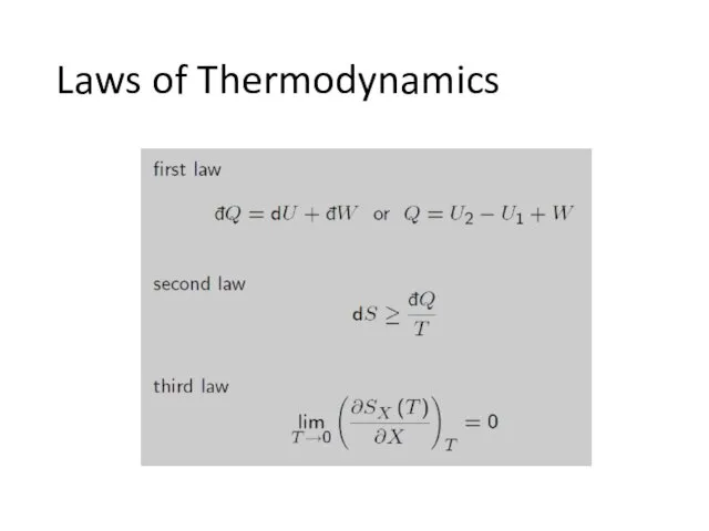
Laws of Thermodynamics
Laws of Thermodynamics
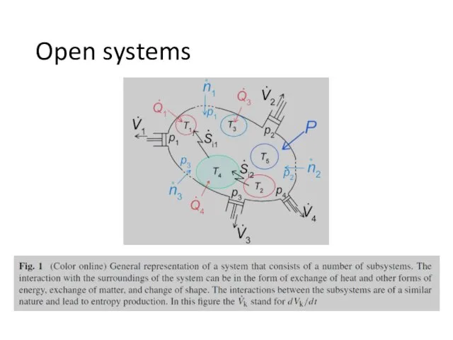
Open systems
Open systems
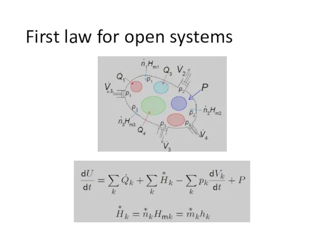
First law for open systems
First law for open systems
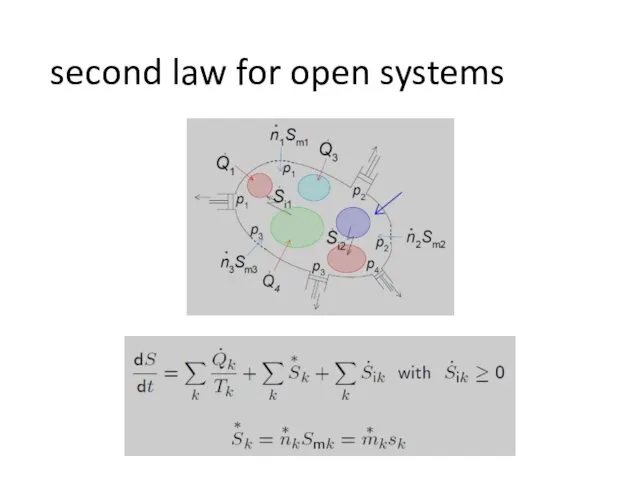
second law for open systems
second law for open systems
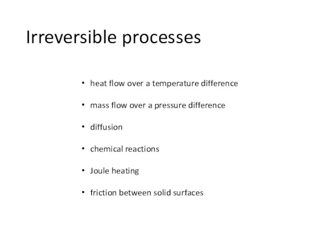
Irreversible processes
heat flow over a temperature difference
mass flow over a pressure
Irreversible processes
heat flow over a temperature difference
mass flow over a pressure
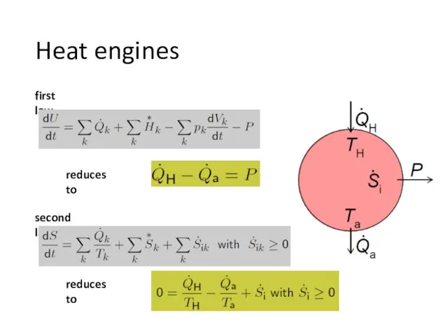
Heat engines
first law
reduces to
second law
reduces to
Heat engines
first law
reduces to
second law
reduces to
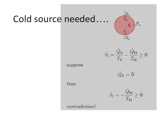
Cold source needed….
Cold source needed….
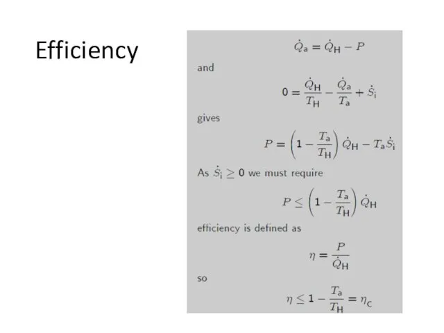
Efficiency
Efficiency
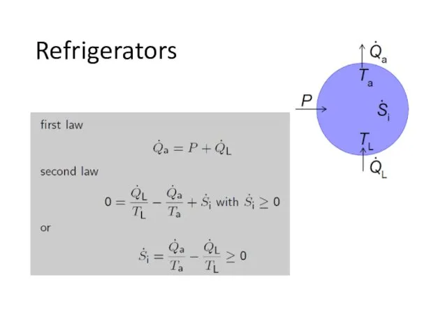
Refrigerators
Refrigerators
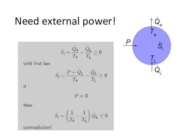
Need external power!
Need external power!
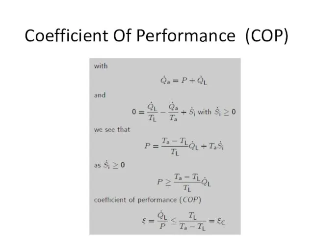
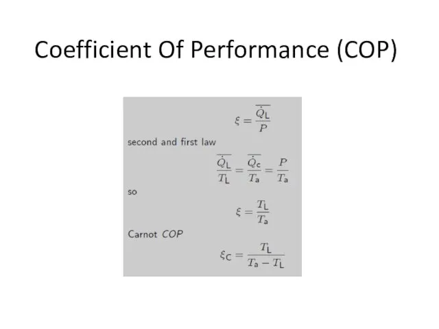
Coefficient Of Performance (COP)
Coefficient Of Performance (COP)
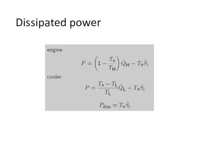
Dissipated power
Dissipated power
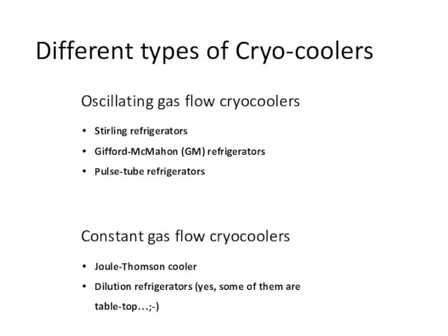
Different types of Cryo-coolers
Oscillating gas flow cryocoolers
Stirling refrigerators
Gifford-McMahon (GM) refrigerators
Pulse-tube refrigerators
Constant
Different types of Cryo-coolers
Oscillating gas flow cryocoolers
Stirling refrigerators
Gifford-McMahon (GM) refrigerators
Pulse-tube refrigerators
Constant
Joule-Thomson coolers
Invented by Carl von Linde and William Hampson, it is
Joule-Thomson coolers
Invented by Carl von Linde and William Hampson, it is
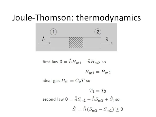
Joule-Thomson: thermodynamics
Joule-Thomson: thermodynamics
Joule-Thomson cooler
Schematic diagram of a JT liquefier
At the liquid side a
Joule-Thomson cooler
Schematic diagram of a JT liquefier
At the liquid side a
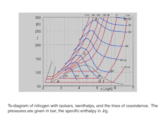
Ts-diagram of nitrogen with isobars, isenthalps, and the lines of coexistence.
Ts-diagram of nitrogen with isobars, isenthalps, and the lines of coexistence.
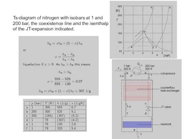
Ts-diagram of nitrogen with isobars at 1 and 200 bar, the
Ts-diagram of nitrogen with isobars at 1 and 200 bar, the
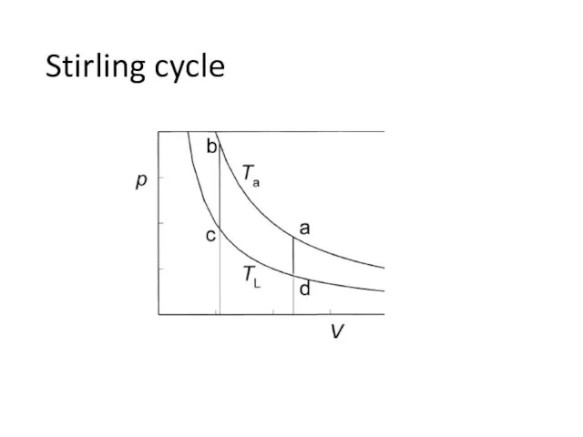
Stirling cycle
Stirling cycle
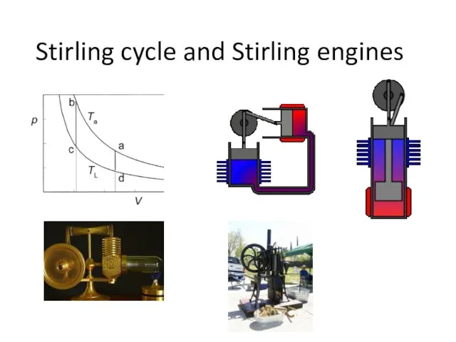
Stirling cycle and Stirling engines
Stirling cycle and Stirling engines
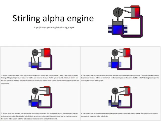
Stirling alpha engine
https://en.wikipedia.org/wiki/Stirling_engine
Stirling alpha engine
https://en.wikipedia.org/wiki/Stirling_engine
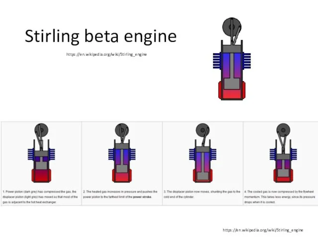
Stirling beta engine
https://en.wikipedia.org/wiki/Stirling_engine
https://en.wikipedia.org/wiki/Stirling_engine
Stirling beta engine
https://en.wikipedia.org/wiki/Stirling_engine
https://en.wikipedia.org/wiki/Stirling_engine
Stirling Coolers
https://en.wikipedia.org/wiki/File:Schematic_Stirling_Cooler.jpg
The thermal contact with the surroundings at the temperatures Ta
Stirling Coolers
https://en.wikipedia.org/wiki/File:Schematic_Stirling_Cooler.jpg
The thermal contact with the surroundings at the temperatures Ta
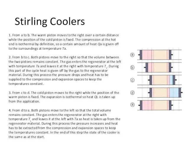
1. From a to b. The warm piston moves to the
1. From a to b. The warm piston moves to the
Stirling cooler
Stirling cooler
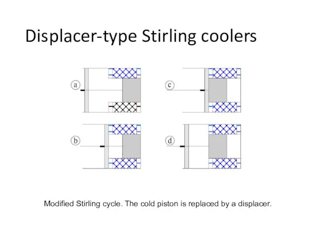
Displacer-type Stirling coolers
Modified Stirling cycle. The cold piston is replaced by
Displacer-type Stirling coolers
Modified Stirling cycle. The cold piston is replaced by
PULSE-TUBE REFRIGERATORS (PTRs)
PULSE-TUBE REFRIGERATORS (PTRs)
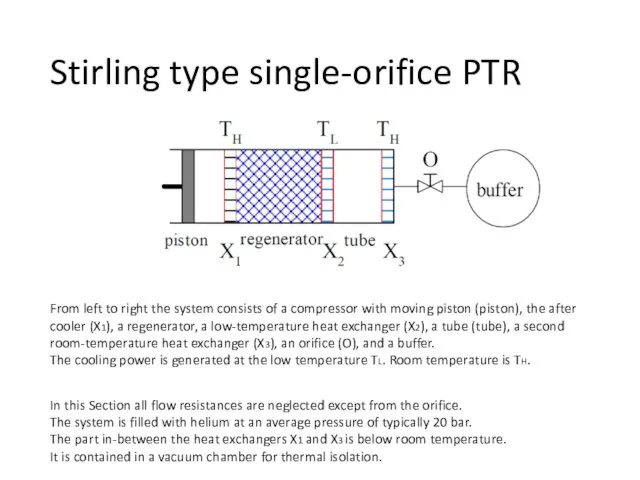
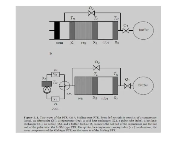
Stirling type single-orifice PTR
From left to right the system consists of
Stirling type single-orifice PTR
From left to right the system consists of
Some remarks…
The piston moves the gas back and forth and generates
Some remarks…
The piston moves the gas back and forth and generates
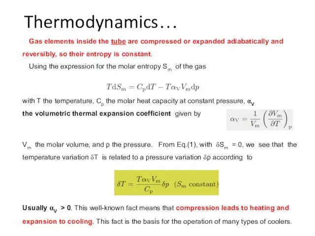
Thermodynamics…
with T the temperature, Cp the molar heat capacity at constant
Thermodynamics…
with T the temperature, Cp the molar heat capacity at constant
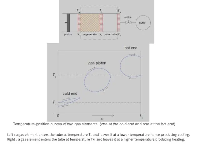
Left : a gas element enters the tube at temperature TL
Left : a gas element enters the tube at temperature TL
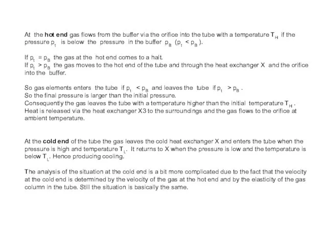
At the hot end gas flows from the buffer via the
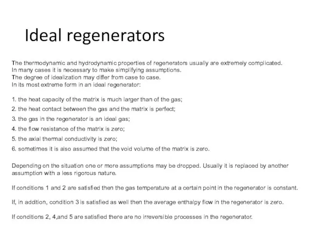
Ideal regenerators
The thermodynamic and hydrodynamic properties of regenerators usually are extremely
Ideal regenerators
The thermodynamic and hydrodynamic properties of regenerators usually are extremely
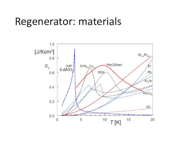
Regenerator: materials
Regenerator: materials
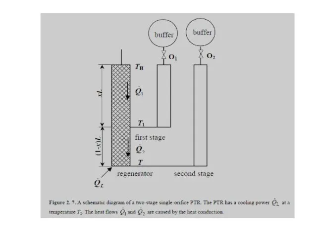
The figure illustrates the cooling process at the cold end in
The figure illustrates the cooling process at the cold end in
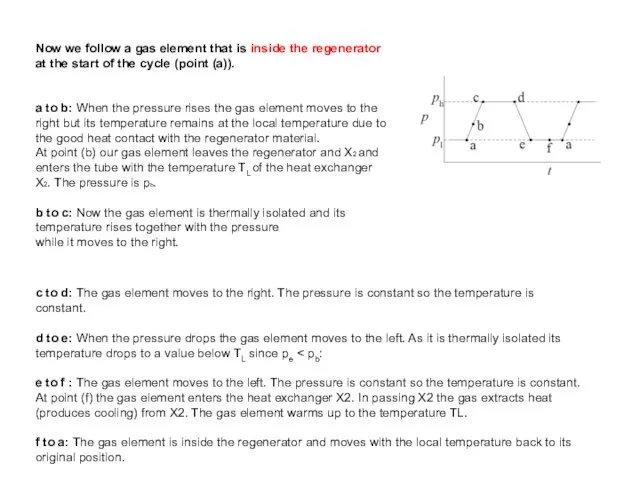
Now we follow a gas element that is inside the regenerator
Now we follow a gas element that is inside the regenerator
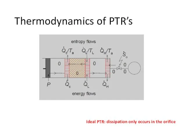
Thermodynamics of PTR’s
Ideal PTR: dissipation only occurs in the orifice
Thermodynamics of PTR’s
Ideal PTR: dissipation only occurs in the orifice
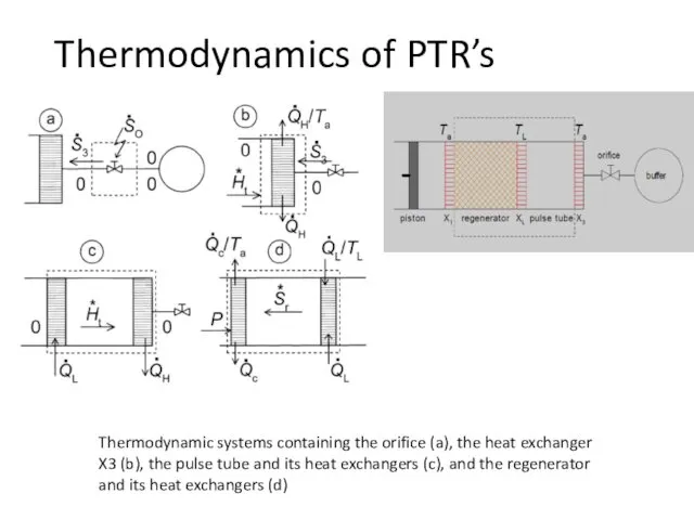
Thermodynamic systems containing the orifice (a), the heat exchanger X3 (b),
Thermodynamic systems containing the orifice (a), the heat exchanger X3 (b),
Coefficient Of Performance (COP)
Coefficient Of Performance (COP)
Pulse-tube refrigerators have their origin in an observation that W. E.
Pulse-tube refrigerators have their origin in an observation that W. E.
The PTR has no moving parts in the low-temperature region, and,
The main breakthrough came in 1984, when Mikulin and his co-workers
The main breakthrough came in 1984, when Mikulin and his co-workers
PhD Thesis
Low-temperature cryocooling / by Irina Tanaeva. -
Eindhoven : Technische
PhD Thesis
Low-temperature cryocooling / by Irina Tanaeva. -
Eindhoven : Technische
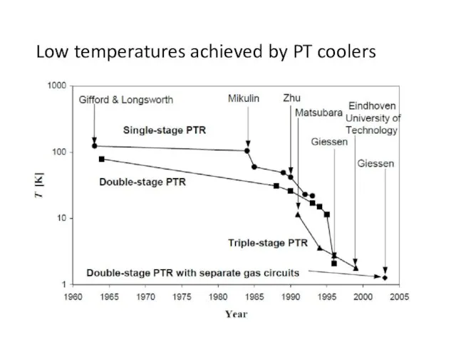
Low temperatures achieved by PT coolers
Low temperatures achieved by PT coolers
![Additional cooling power [5] Experimental results on the free cooling](/_ipx/f_webp&q_80&fit_contain&s_1440x1080/imagesDir/jpg/88952/slide-53.jpg)
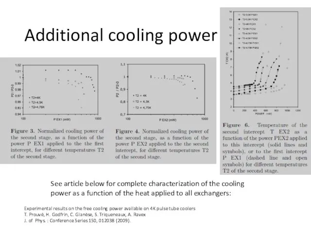
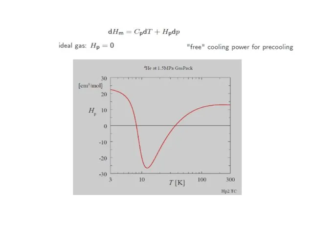
Additional cooling power
[5] Experimental results on the free cooling power available
Additional cooling power
[5] Experimental results on the free cooling power available
Additional cooling power
Experimental results on the free cooling power available on
Additional cooling power
Experimental results on the free cooling power available on
Commercial pulse-tubes
Commercial pulse-tubes
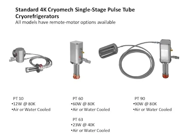
PT 10
12W @ 80K
Air or Water Cooled
PT 60
60W @ 80K
Air or
PT 10
12W @ 80K
Air or Water Cooled
PT 60
60W @ 80K
Air or
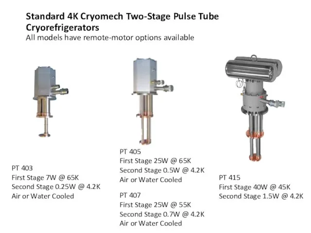
Standard 4K Cryomech Two-Stage Pulse Tube Cryorefrigerators
All models have remote-motor options
Standard 4K Cryomech Two-Stage Pulse Tube Cryorefrigerators All models have remote-motor options
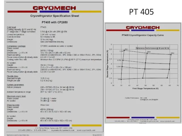
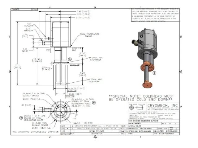
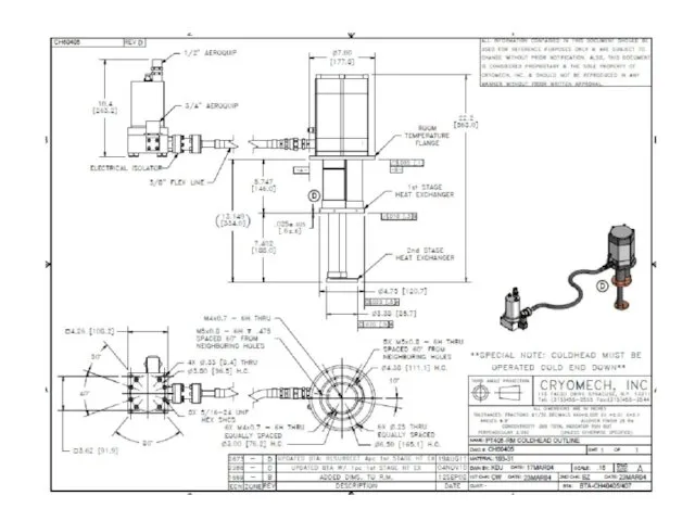
PT 405
PT 405
Features of Pulse Tube Cryorefrigerators
Long mean time between maintenance
Features of Pulse Tube Cryorefrigerators
Long mean time between maintenance
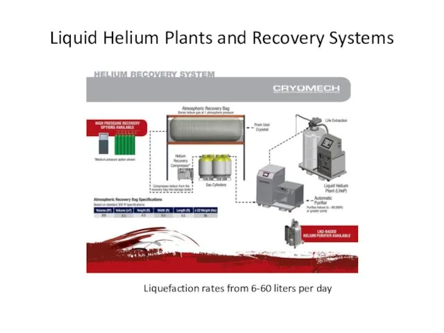
Liquid Helium Plants and Recovery Systems
Liquefaction rates from 6-60 liters per
Liquid Helium Plants and Recovery Systems
Liquefaction rates from 6-60 liters per
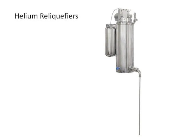
Helium Reliquefiers
Helium Reliquefiers
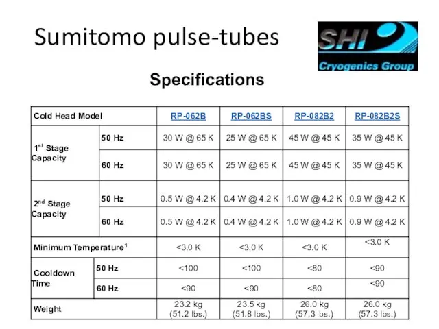
Sumitomo pulse-tubes
Specifications
Sumitomo pulse-tubes
Specifications
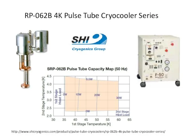
RP-062B 4K Pulse Tube Cryocooler Series
http://www.shicryogenics.com/products/pulse-tube-cryocoolers/rp-062b-4k-pulse-tube-cryocooler-series/
RP-062B 4K Pulse Tube Cryocooler Series
http://www.shicryogenics.com/products/pulse-tube-cryocoolers/rp-062b-4k-pulse-tube-cryocooler-series/
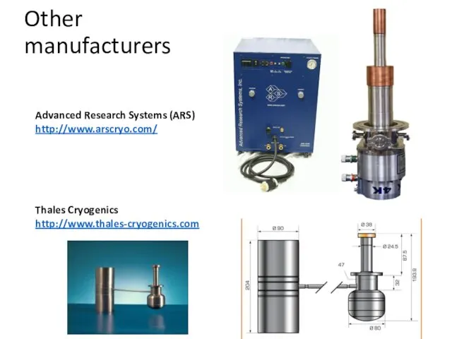
Other
manufacturers
Advanced Research Systems (ARS)
http://www.arscryo.com/
Thales Cryogenics
http://www.thales-cryogenics.com
Other
manufacturers
Advanced Research Systems (ARS)
http://www.arscryo.com/
Thales Cryogenics
http://www.thales-cryogenics.com
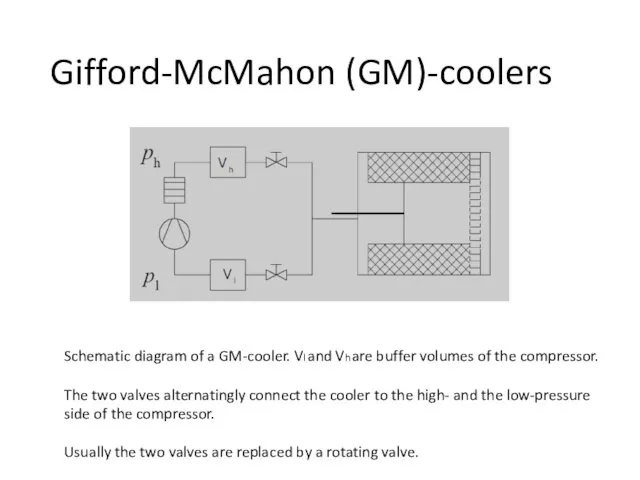
Gifford-McMahon (GM)-coolers
Schematic diagram of a GM-cooler. Vl and Vh are buffer
Gifford-McMahon (GM)-coolers
Schematic diagram of a GM-cooler. Vl and Vh are buffer
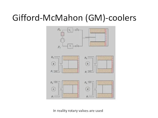
Gifford-McMahon (GM)-coolers
In reality rotary valves are used
Gifford-McMahon (GM)-coolers
In reality rotary valves are used
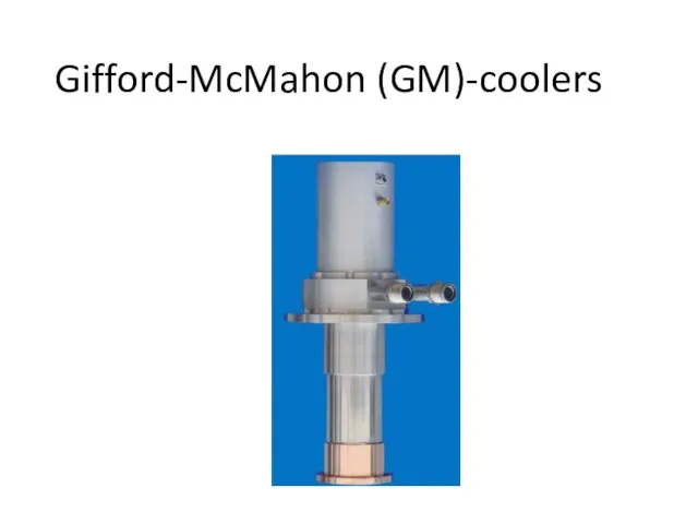
Gifford-McMahon (GM)-coolers
Gifford-McMahon (GM)-coolers
 Фотоефект та його застосування
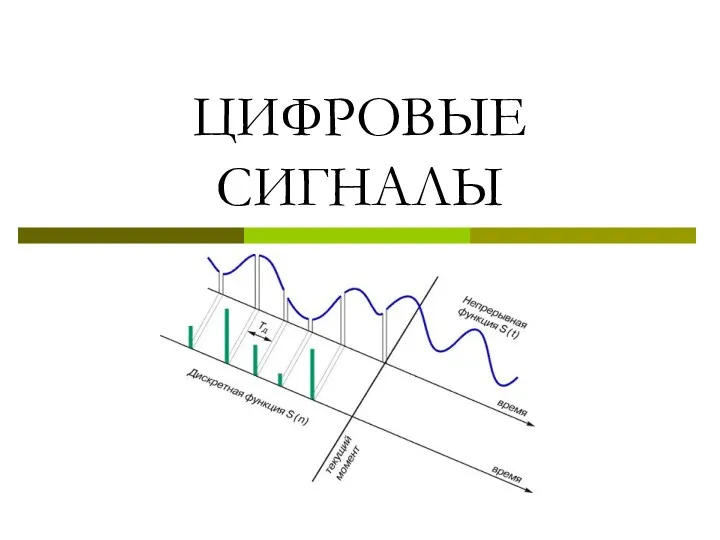 Цифровые сигналы
 Волновая оптика (11 класс)
 Законы Ньютона. 10 Класс
 Давление твёрдых тел. Вычисление давления на опору
 Электрический ток в полупроводниках
 Оптические явления. Урок для 8 класса
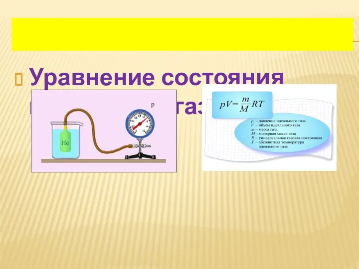 Уравнение состояния идеального газа
 Кинематика движения материальной точки
 Параллельное соединение проводников
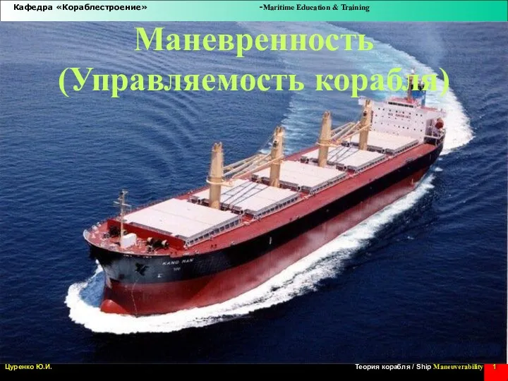 Маневренность (Управляемость корабля)
 Расчёт основных характеристик цепей переменного тока
 Линза. Применение линз. Виды линз. Построение изображения в линзах
 Инфракрасная спектроскопия
 Презентация для будущих первоклассников на тему Я - наблюдатель
 Небольшое небесное тело комета
 Классификация и технические характеристики военных радиостанций. (Лекция 7)
 Презентация к урокупо теме Третий закон Ньютона, 9 кл.
 Введение в динамику системы. Масса. Центр масс. Моменты инерции
 Дисциплина Прикладная механика. Основные понятия и определения
 Работа силы. 10 класс
 Знакомство с бытовой швейной машиной
 Шкала электромагнитных волн
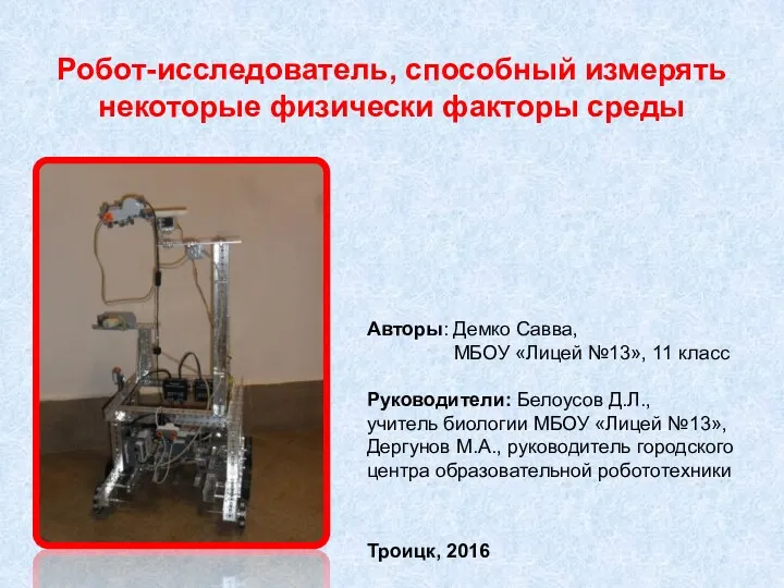 Робот-исследователь, способный измерять некоторые физические факторы среды
 University physics. Forces review of basic concepts
 Магнитное поле в веществе. Уравнения Максвелла
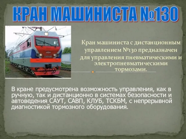 Кран машиниста поезда, с дистанционным управлением №130
 8 класс