Insulators and Conductors in electric field. Capacitance, Dielectrics. Current, resistance. Electromotive Force презентация
- Insulators and Conductors in electric field. Capacitance, Dielectrics. Current, resistance. Electromotive Force

Содержание
- 2. Lecture 9 Insulators and Conductors in electric field. Capacitance, Dielectrics. Current, resistance. Electromotive Force.
- 3. Conductors and Insulators Electrical conductors are materials in which some of the electrons are free, that
- 4. Capacitance The capacitance C of a capacitor is defined as the ratio of the magnitude of
- 5. Parallel – Plate Capacitor A parallel-plate capacitor consists of two parallel conducting plates, each of area
- 6. Using the Gauss theorem we can find that the value of the electric field between plates
- 7. Capacitance of various Capacitors
- 8. The electric field between the plates of a parallel-plate capacitor is uniform near the center but
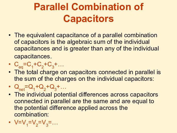
- 9. Parallel Combination of Capacitors Ceq=C1+C2 Qnet=Q1+Q2 V=V1=V2
- 10. Parallel Combination of Capacitors The equivalent capacitance of a parallel combination of capacitors is the algebraic
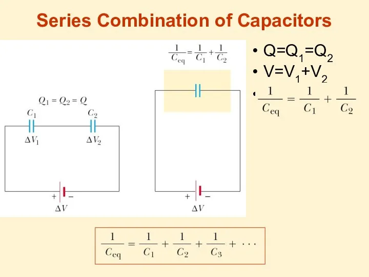
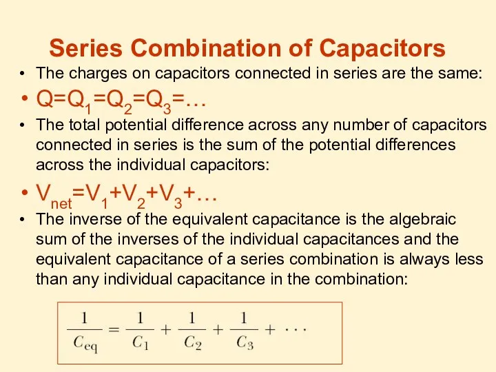
- 11. Series Combination of Capacitors Q=Q1=Q2 V=V1+V2 1
- 12. Series Combination of Capacitors The charges on capacitors connected in series are the same: Q=Q1=Q2=Q3=… The
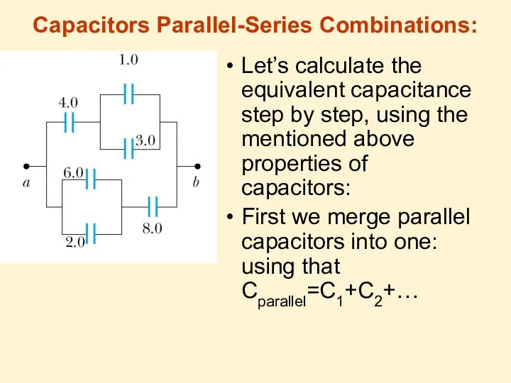
- 13. Capacitors Parallel-Series Combinations: Let’s calculate the equivalent capacitance step by step, using the mentioned above properties
- 14. 1. Merging parallel capacitors:
- 15. 2. Joining serial capacitors: In circles we have merged capacitors: Then we join series conductors: And
- 16. Energy Stored in a Charged Capacitor If a capacitor has charge Q then it’s difference of
- 17. Energy Stored in a Charged Capacitor The work done in charging the capacitor appears as electric
- 18. Energy in a Capacitor Usually V is used instead of ΔV for the difference of potentials,
- 19. Energy in Electric Fields Let’s take a parallel-plate capacitor: V - the potential difference between the
- 20. Energy density of Electric Field The volume, occupied by the electric field is Ad, then the
- 21. Dielectrics Many materials (like paper, rubber, plastics, glass …) do not conduct electricity easily – we
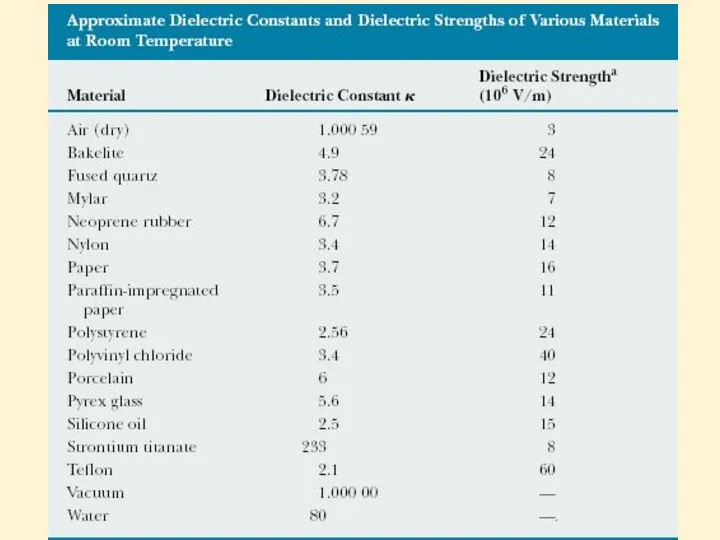
- 22. Dielectric strength The dielectric strength equals the maximum electric field that can exist in a dielectric
- 24. Atomic Description of Dielectrics Dielectric can be made up of polar molecules. The dipoles are randomly
- 25. Polar and Nonpolar molecules of Dielectric The molecules of the dielectric can be polar or nonpolar.
- 26. Dielectric polarization The degree of alignment of the molecules with the electric field depends on temperature
- 27. Induced Electric field in Dielectric When an external field E0 is applied, a torque is exerted
- 28. Capacitor with Dielectric So the electric field is k times less in a capacitor with a
- 29. As the charge Q on the capacitor is not changed: C0=Q/V0, V=V0/k C=Q/V=kC0V0/V0=kC0 C=kC0 So the
- 30. Usage of Dielectrics in Capacitors Insulating materials have k>1 and dielectric strength greater than that of
- 31. Electric Current Electric current (or just current) is defined as the total charge that passes through
- 32. Current direction By convention the direction of the current is the direction of positive charges would
- 33. Ohm’s Law Ohm’s law states that For many materials the resistance is constant over a wide
- 34. Electromotive Force A device with the ability to maintain potential difference between two points is called
- 36. Скачать презентацию
Lecture 9
Insulators and Conductors in electric field.
Capacitance, Dielectrics.
Current, resistance.
Electromotive Force.
Lecture 9
Insulators and Conductors in electric field.
Capacitance, Dielectrics.
Current, resistance.
Electromotive Force.
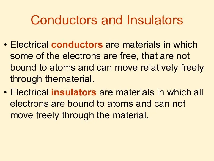
Conductors and Insulators
Electrical conductors are materials in which some of the
Conductors and Insulators
Electrical conductors are materials in which some of the
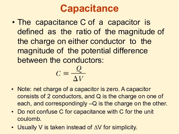
Capacitance
The capacitance C of a capacitor is defined as the ratio
Capacitance
The capacitance C of a capacitor is defined as the ratio
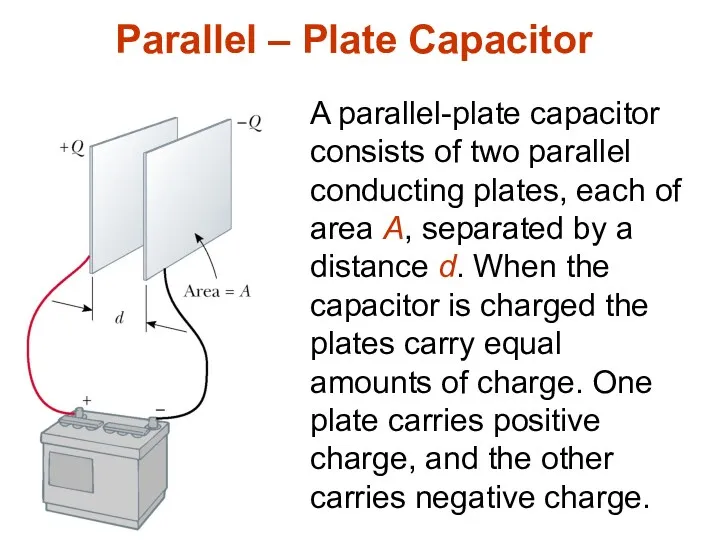
Parallel – Plate Capacitor
A parallel-plate capacitor consists of two parallel conducting
Parallel – Plate Capacitor
A parallel-plate capacitor consists of two parallel conducting
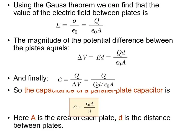
Using the Gauss theorem we can find that the value of
Using the Gauss theorem we can find that the value of
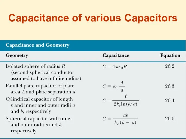
Capacitance of various Capacitors
Capacitance of various Capacitors
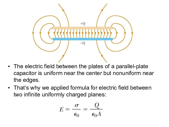
The electric field between the plates of a parallel-plate capacitor is
The electric field between the plates of a parallel-plate capacitor is
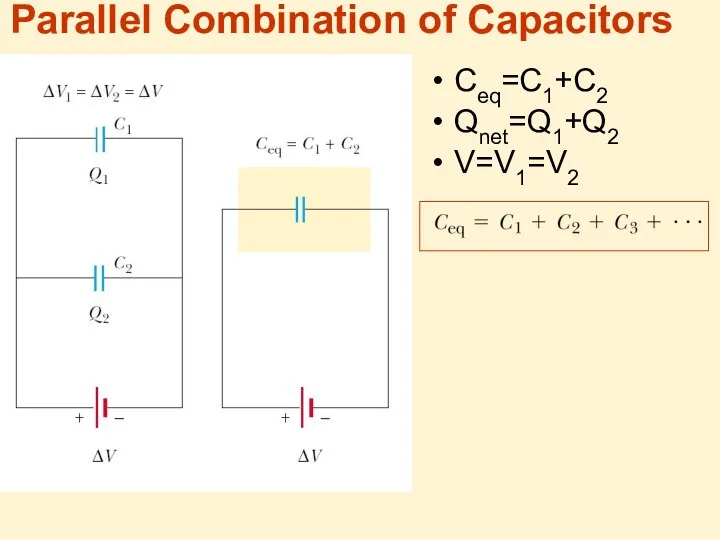
Parallel Combination of Capacitors
Ceq=C1+C2
Qnet=Q1+Q2
V=V1=V2
Parallel Combination of Capacitors
Ceq=C1+C2
Qnet=Q1+Q2
V=V1=V2
Parallel Combination of Capacitors
The equivalent capacitance of a parallel combination of
Parallel Combination of Capacitors
The equivalent capacitance of a parallel combination of
Series Combination of Capacitors
Q=Q1=Q2
V=V1+V2
1
Series Combination of Capacitors
Q=Q1=Q2
V=V1+V2
1
Series Combination of Capacitors
The charges on capacitors connected in series are
Series Combination of Capacitors
The charges on capacitors connected in series are
Capacitors Parallel-Series Combinations:
Let’s calculate the equivalent capacitance step by step, using
Capacitors Parallel-Series Combinations:
Let’s calculate the equivalent capacitance step by step, using
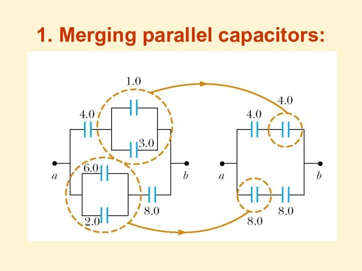
1. Merging parallel capacitors:
1. Merging parallel capacitors:
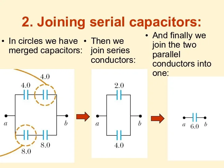
2. Joining serial capacitors:
In circles we have merged capacitors:
Then we join
2. Joining serial capacitors:
In circles we have merged capacitors:
Then we join
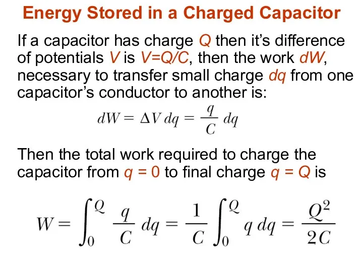
Energy Stored in a Charged Capacitor
If a capacitor has charge Q
Energy Stored in a Charged Capacitor
If a capacitor has charge Q
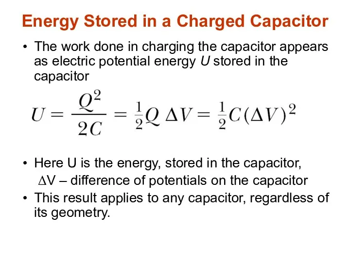
Energy Stored in a Charged Capacitor
The work done in charging the
Energy Stored in a Charged Capacitor
The work done in charging the
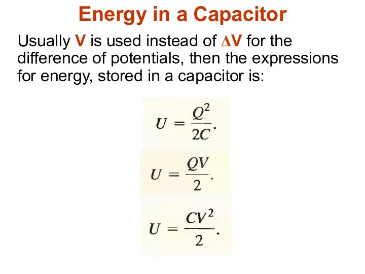
Energy in a Capacitor
Usually V is used instead of ΔV for
Energy in a Capacitor
Usually V is used instead of ΔV for
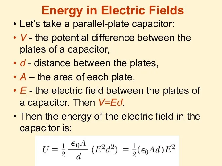
Energy in Electric Fields
Let’s take a parallel-plate capacitor:
V - the potential
Energy in Electric Fields
Let’s take a parallel-plate capacitor:
V - the potential
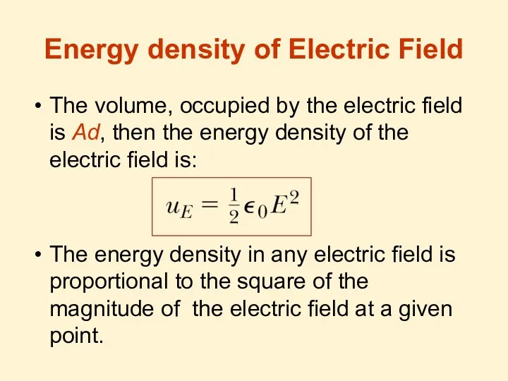
Energy density of Electric Field
The volume, occupied by the electric field
Energy density of Electric Field
The volume, occupied by the electric field
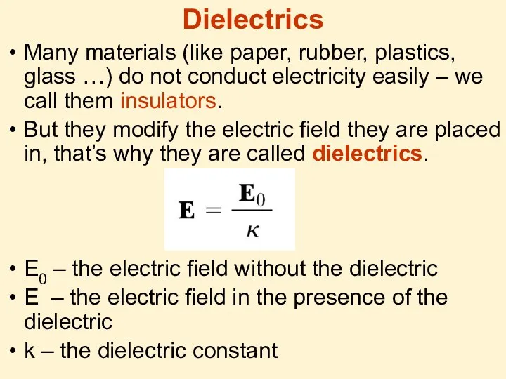
Dielectrics
Many materials (like paper, rubber, plastics, glass …) do not conduct
Dielectrics
Many materials (like paper, rubber, plastics, glass …) do not conduct
Dielectric strength
The dielectric strength equals the maximum electric field that can
Dielectric strength
The dielectric strength equals the maximum electric field that can
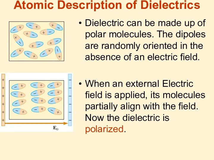
Atomic Description of Dielectrics
Dielectric can be made up of polar molecules.
Atomic Description of Dielectrics
Dielectric can be made up of polar molecules.
Polar and Nonpolar molecules of Dielectric
The molecules of the dielectric can
Polar and Nonpolar molecules of Dielectric
The molecules of the dielectric can
Dielectric polarization
The degree of alignment of the molecules with the electric
Dielectric polarization
The degree of alignment of the molecules with the electric
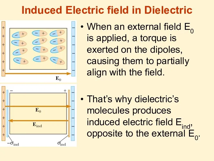
Induced Electric field in Dielectric
When an external field E0 is applied,
Induced Electric field in Dielectric
When an external field E0 is applied,
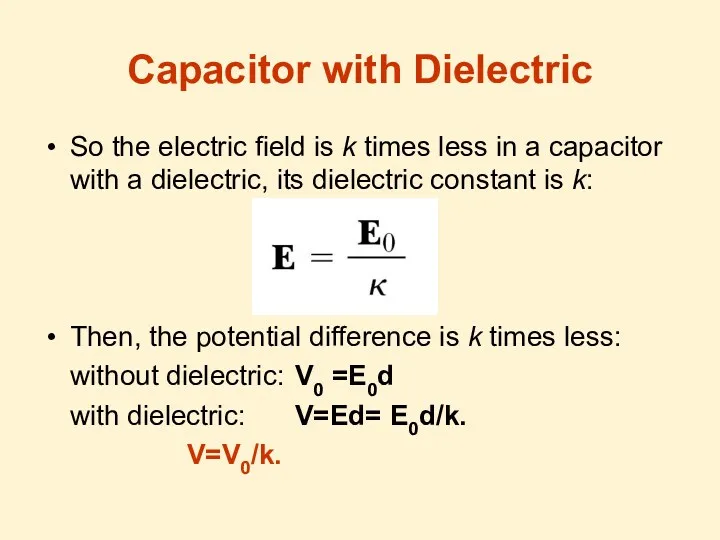
Capacitor with Dielectric
So the electric field is k times less in
Capacitor with Dielectric
So the electric field is k times less in
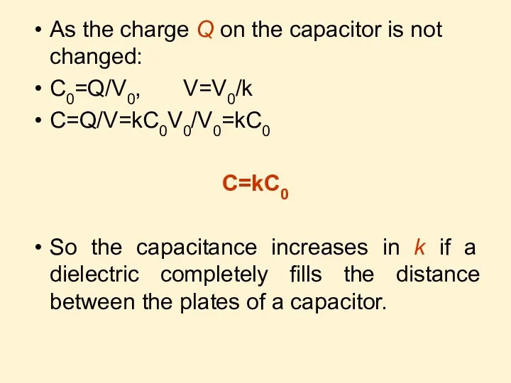
As the charge Q on the capacitor is not changed:
C0=Q/V0, V=V0/k
C=Q/V=kC0V0/V0=kC0
C=kC0
So
As the charge Q on the capacitor is not changed:
C0=Q/V0, V=V0/k
C=Q/V=kC0V0/V0=kC0
C=kC0
So
Usage of Dielectrics in Capacitors
Insulating materials have k>1 and dielectric strength
Usage of Dielectrics in Capacitors
Insulating materials have k>1 and dielectric strength
Electric Current
Electric current (or just current) is defined as the total
Electric Current
Electric current (or just current) is defined as the total
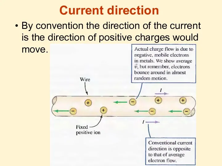
Current direction
By convention the direction of the current is the direction
Current direction
By convention the direction of the current is the direction
Ohm’s Law
Ohm’s law states that
For many materials the resistance is
Ohm’s Law
Ohm’s law states that
For many materials the resistance is
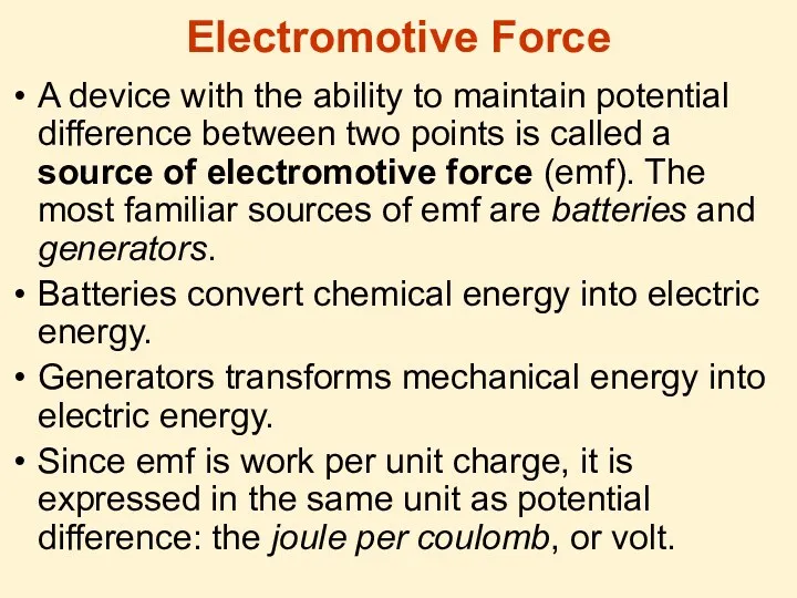
Electromotive Force
A device with the ability to maintain potential difference between
Electromotive Force
A device with the ability to maintain potential difference between
 Саївський НВК Фізика-8
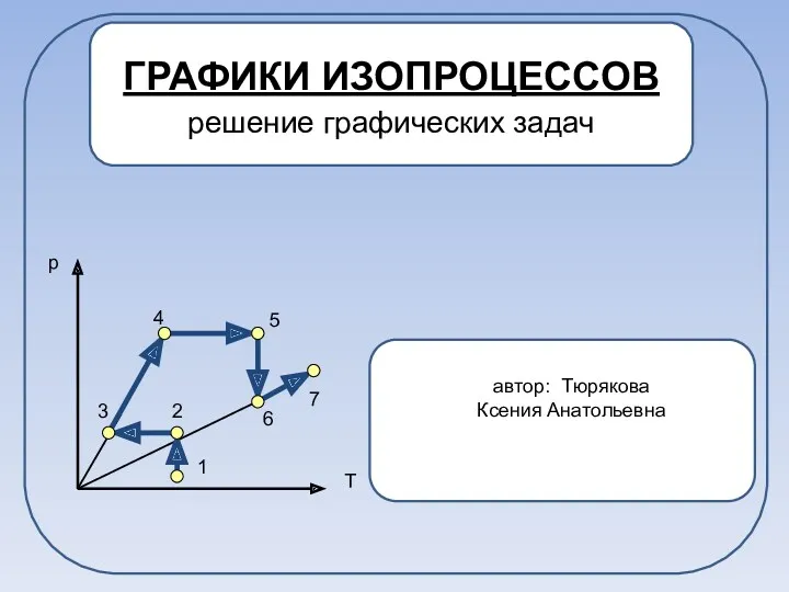 Графики изопроцессов. Решение графических задач
 Технология ТО и ремонта двигателя автомобиля Skoda Codiaq 1.4 6 MT. Сварка высоколегированных сталей
 Виды калибров
 Реактивний рух в природі та техніці
 Подъемно-транспортное оборудование
 Рабочие программы
 Типы подвесок автомобилей
 Drivetrain System
 Определение угла погасания и знака удлинения. Исследования в скрещенных николях, в проходящем свете
 Технология проблемного обучения в условиях перехода на ФГОС
 электрический ток в металлах
 Импульс тела. Закон сохранения импульса. Реактивное движение в природе и технике
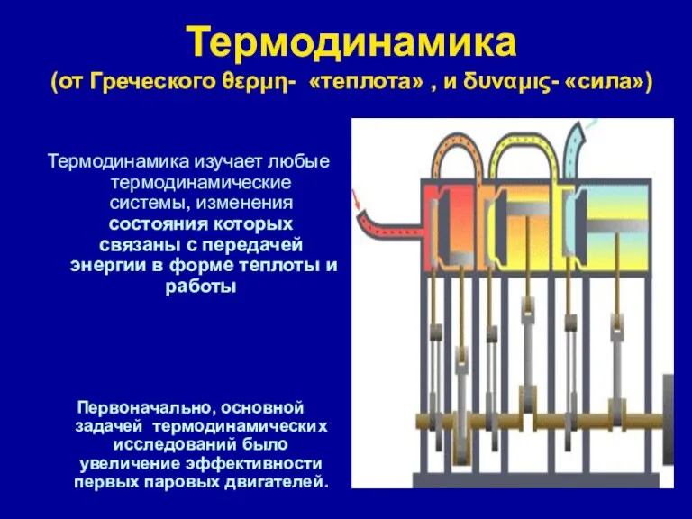 Термодинамика. Химическая термодинамика
 Электр ток көздері. Ом заңы
 Методическая разработка по методике В.Ф. Шаталова для организации учебной деятельности учащихся по физике. На примере темы Электрический ток. 8 класс
 Явления взаимной индукции
 Проект Волшебный мир зазеркалья. Свойства зеркала
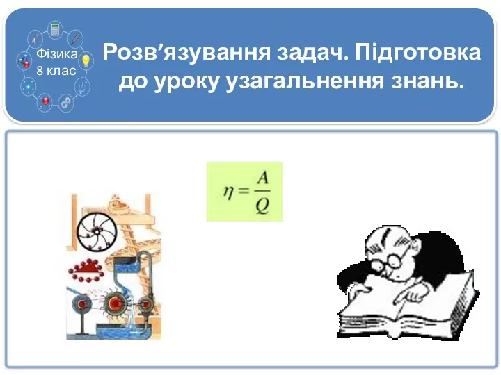 Урок узагальнення та систематизації знань з теми Теплові явища. Розв’язування задач. 8 клас
 Плавание тел
 Проводники, непроводники и полупроводники электричества
 Электронные системы питания двигателей
 Электромагнитная картина мира
 Взаимосвязь массы и энергии покоя
 Соединение проводников и источников тока. Тепловое действие тока
 Последовательное соединение проводников
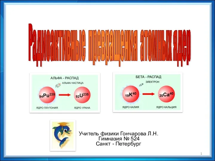 Радиоактивные превращения атомных ядер. 9 класс
 Преломление света. Дисперсия света