- Internal Сombustion Engine. Fuel Systems. The diesel injection system

Содержание
- 2. Basic Functions of Injection Systems The basic functions of a diesel injection system can be broken
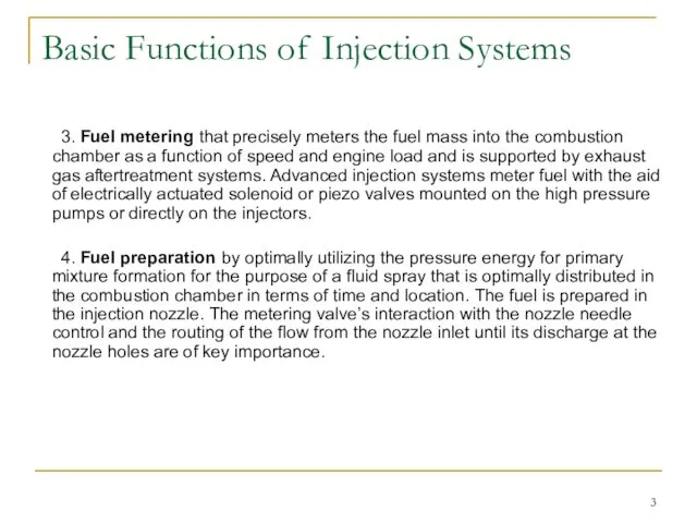
- 3. Basic Functions of Injection Systems 3. Fuel metering that precisely meters the fuel mass into the
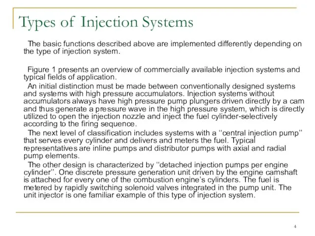
- 4. Types of Injection Systems The basic functions described above are implemented differently depending on the type
- 5. Fig. 1 Present injection system designs and their applications
- 6. Types of Injection Systems Accumulator systems on the other hand have a central high pressure pump
- 7. Fig. 2 Comparison of pressure and lift controlled injection
- 8. Types The implementation of common rail systems in virtually every engine can be expected in the
- 9. Inline Pumps Main Features – There is one pump element per engine cylinder and the elements
- 10. Axial Distributor Pumps Main Features – There is one axial pump elements for all engine cylinders.
- 11. Radial Distributor Pumps – The fuel flow is distributed to outlets to the engine cylinders. –
- 12. Unit Injectors (Unit Injectors) Main Features – One unit injector per engine cylinder is integrated in
- 13. Unit Pump Systems (Unit Pumps) – It is driven by an underhead engine camshaft (commercial vehicles).
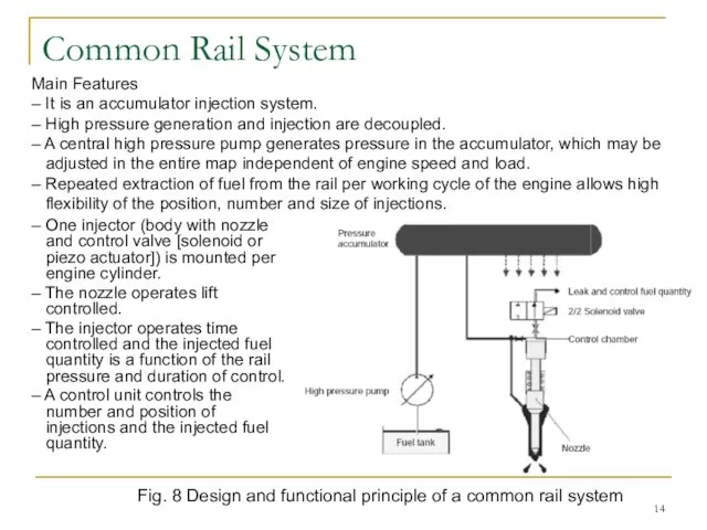
- 14. Common Rail System – One injector (body with nozzle and control valve [solenoid or piezo actuator])
- 15. Common Rail System Design Unlike cam-driven injection systems, the common rail system decouples pressure generation and
- 16. A common rail system can be divided into the following subsystems (Fig. 9): – low pressure
- 17. Common Rail System Design Driven by the engine, the continuously operating high pressure pump generates the
- 18. CR Injectors Common rail injectors with identical basic functions are employed in car and commercial vehicle
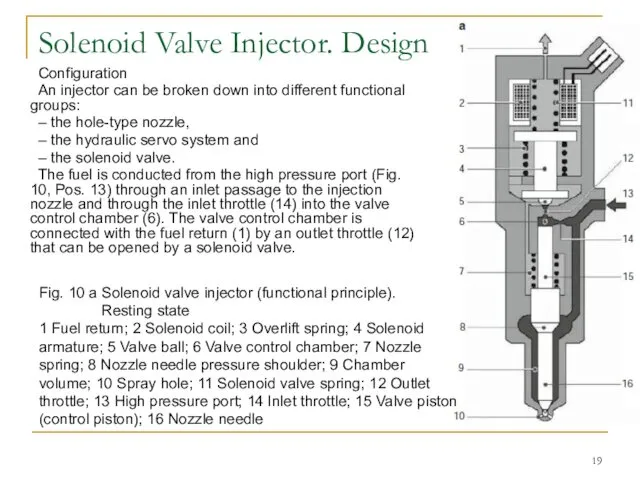
- 19. Solenoid Valve Injector. Design Configuration An injector can be broken down into different functional groups: –
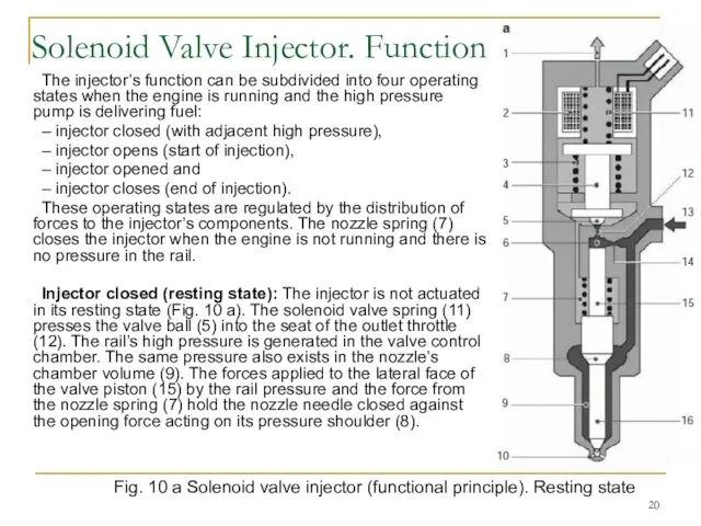
- 20. Solenoid Valve Injector. Function The injector’s function can be subdivided into four operating states when the
- 21. Fig. 10 b Solenoid valve injector (functional principle). Injector opens Injector opens (start of injection): The
- 22. Injector opened: The nozzle needle’s opening speed is determined by the differential flow between the inlet
- 24. Скачать презентацию
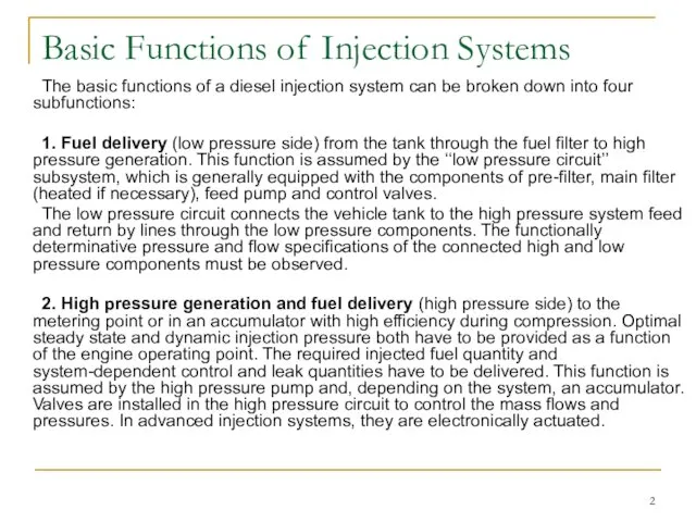
Basic Functions of Injection Systems
The basic functions of a diesel injection
Basic Functions of Injection Systems
The basic functions of a diesel injection
Basic Functions of Injection Systems
3. Fuel metering that precisely meters the
Basic Functions of Injection Systems
3. Fuel metering that precisely meters the
Types of Injection Systems
The basic functions described above are implemented differently
Types of Injection Systems
The basic functions described above are implemented differently
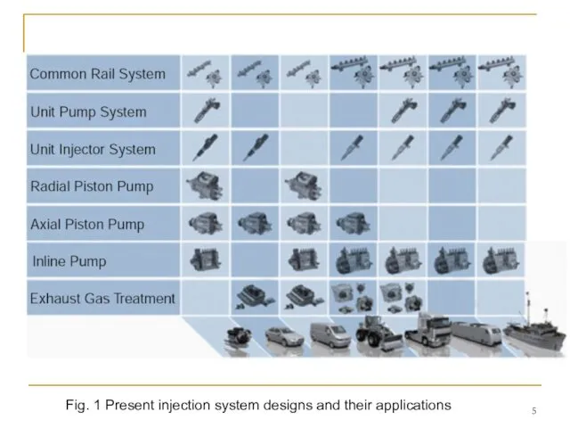
Fig. 1 Present injection system designs and their applications
Fig. 1 Present injection system designs and their applications
Types of Injection Systems
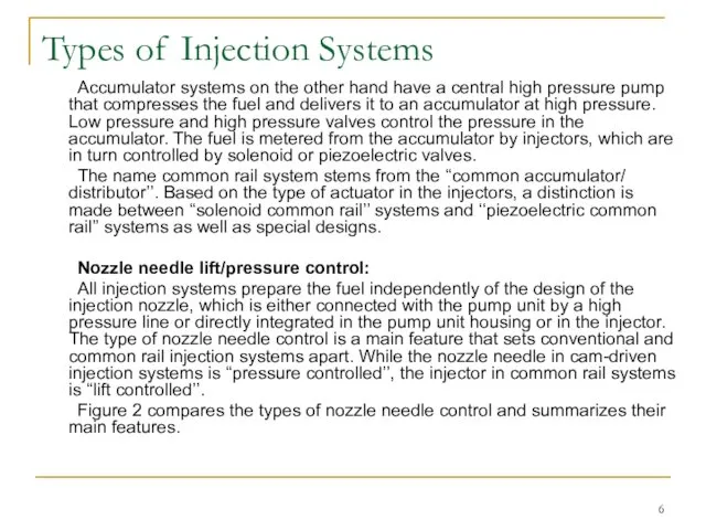
Accumulator systems on the other hand have a
Types of Injection Systems
Accumulator systems on the other hand have a
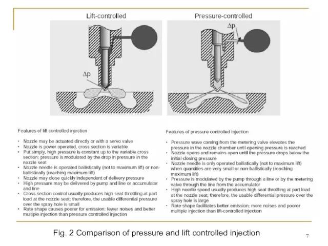
Fig. 2 Comparison of pressure and lift controlled injection
Fig. 2 Comparison of pressure and lift controlled injection
Types
The implementation of common rail systems in virtually every engine can
Types
The implementation of common rail systems in virtually every engine can
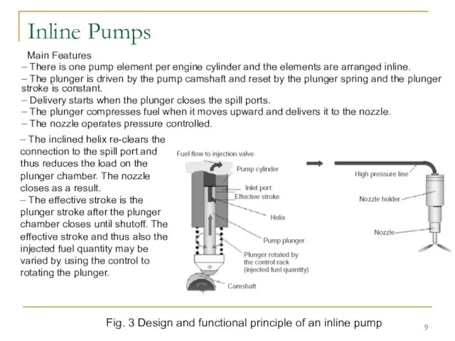
Inline Pumps
Main Features
– There is one pump element per engine cylinder
Inline Pumps
Main Features
– There is one pump element per engine cylinder
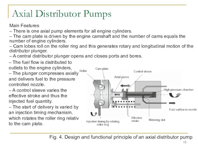
Axial Distributor Pumps
Main Features
– There is one axial pump elements for
Axial Distributor Pumps
Main Features
– There is one axial pump elements for
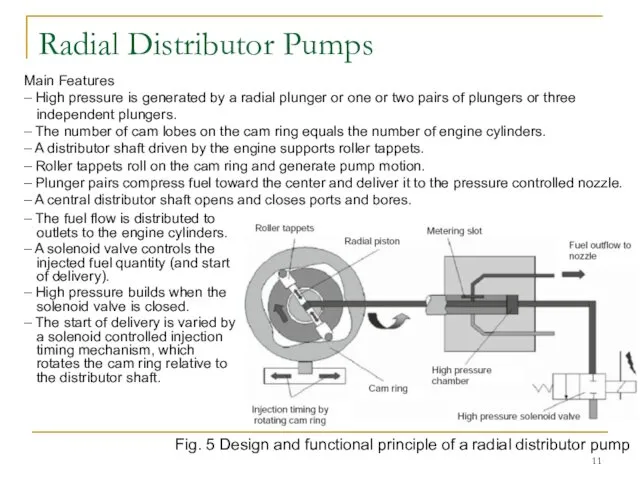
Radial Distributor Pumps
– The fuel flow is distributed to outlets to
Radial Distributor Pumps
– The fuel flow is distributed to outlets to
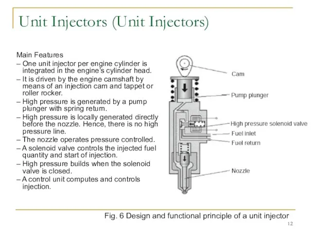
Unit Injectors (Unit Injectors)
Main Features
– One unit injector per engine cylinder
Unit Injectors (Unit Injectors)
Main Features
– One unit injector per engine cylinder
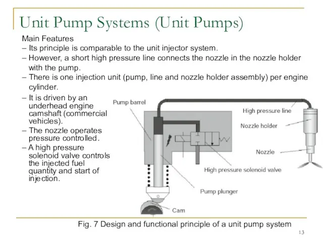
Unit Pump Systems (Unit Pumps)
– It is driven by an underhead
Unit Pump Systems (Unit Pumps)
– It is driven by an underhead
Common Rail System
– One injector (body with nozzle and control valve
Common Rail System
– One injector (body with nozzle and control valve
Common Rail System Design
Unlike cam-driven injection systems, the common rail system
Common Rail System Design
Unlike cam-driven injection systems, the common rail system

A common rail system can be divided into the following subsystems
A common rail system can be divided into the following subsystems
Common Rail System Design
Driven by the engine, the continuously operating high
Common Rail System Design
Driven by the engine, the continuously operating high
CR Injectors
Common rail injectors with identical basic functions are employed in
CR Injectors
Common rail injectors with identical basic functions are employed in
Solenoid Valve Injector. Design
Configuration
An injector can be broken down into different
Solenoid Valve Injector. Design
Configuration
An injector can be broken down into different
Solenoid Valve Injector. Function
The injector’s function can be subdivided into four
Solenoid Valve Injector. Function
The injector’s function can be subdivided into four
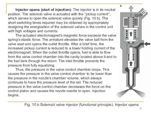
Fig. 10 b Solenoid valve injector (functional principle). Injector opens
Injector opens
Fig. 10 b Solenoid valve injector (functional principle). Injector opens
Injector opens
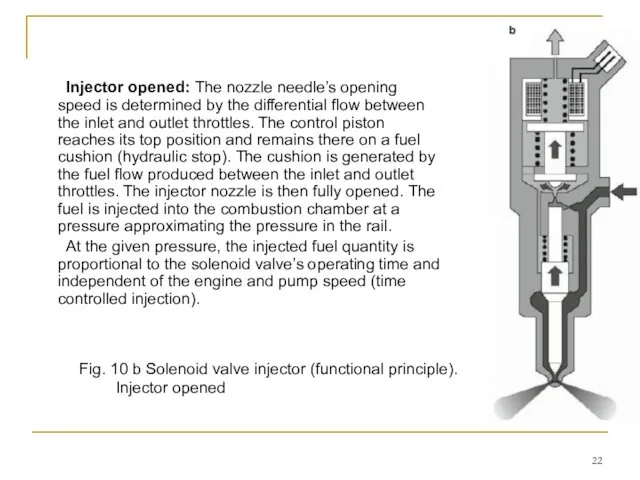
Injector opened: The nozzle needle’s opening speed is determined by the
Injector opened: The nozzle needle’s opening speed is determined by the
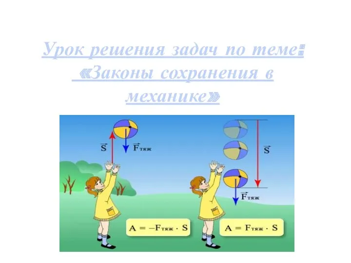 Законы сохранения в механике
 Автоколебания. Природа автоколебаний
 Построение эпюр M, Q и N в балках и рамах
 Физика - удивительная вещь: она интересна, даже если в ней ничего не понимаешь
 Презентация для урока Обнаружение магнитного поля по его действию на электрический ток. 9 класс
 Магниты. Природное ископаемой магнетит. Искусственные магниты. Постоянный и временный магнит. Электромагниты
 Электрический ток. Работа и мощность в цепи постоянного тока. Закон Ома для полной цепи
 Двигатели постоянного тока
 Принципы нанотехнологий
 Необходимость разработки и строительства в Республике Беларусь исследовательского ядерного реактора
 Зеркальные антенны
 Техническое обслуживание и текущий ремонт кузовов
 Перспективы развития атомной энергетики
 Ток в жидкостях. Закон электролиза. Гальваностегия. Гальванопластика
 Колебательное движение
 Методы анализа лекарственных средств
 Явление электромагнитной индукции. Уравнения Максвелла
 Статор орамының МҚК. Топталған ораманың МҚК
 Problem № 2 “Aerosol”
 Механическая энергия
 Плотность тела. формулы
 Моделирование физических процессов
 Свободные затухающие колебания. Вынужденные колебания. Резонанс
 Рулевое управление
 Применения технологии развивающего обучения в 5 классе
 Визуальная, квантовая физика
 Особенности взаимодействия электромагнитного излучения сверхвысокочастотного диапазона с коаксиальными брэгговскими
 Применение приёмов развития критического мышления на уроках физики