- Low-Band Receive Antennas

Содержание
- 2. Tonight’s Topics… Introduction Receiving Basics RX Loops Elongated Terminated Loops EWE Antenna Flag Antenna Pennant Antenna
- 4. Why do we need separate TX and RX antennas? Because, they have different requirements: TX antennas
- 5. Antenna A Antenna B (+3dB gain vs Antenna A) Is Antenna B a better TX Antenna
- 6. Single 720-foot Beverage. Two 720-foot Beverages. Spaced 70 feet apart. Diagrams from ON4UN’s Low Band DXing
- 7. Gain single Beverage: -11.2 dBi Gain two Beverages (70-ft sp): -8.2 dBi So, a pair of
- 8. NO – nothing has been gained! The pattern is still practically identical Front/Back is the same
- 9. How much Negative Gain can we tolerate with RX antennas? Modern receivers are very sensitive. If
- 10. Noise The sum of all unidentified signals (thunderstorms, man-made, cosmic etc.). Requires its own presentation! RX
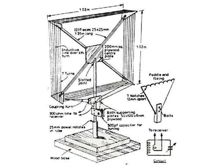
- 11. Receive Loop Antennas
- 12. Max Max Null Null Diagram from Joseph Carr’s Practical Antenna Handbook
- 14. Normal loop in free space Nulls “filled in” by nearby metal objects Diagram from Joseph Carr’s
- 15. Diagram from Joseph Carr’s Practical Antenna Handbook
- 16. Diagram from Joseph Carr’s Practical Antenna Handbook
- 17. Diagram from Joseph Carr’s Practical Antenna Handbook
- 18. Receive Loops Summary Pros Small, lightweight Easy to build Sharp null in 2 directions Cons Poor
- 19. Elongated Terminated Loops Include Ewe, Flag, Pennant and K9AY Terminated loop produces a cardioid pattern Depth
- 20. Theory of Operation Despite the shape, actually a pair of verticals Feedline on top and bottom
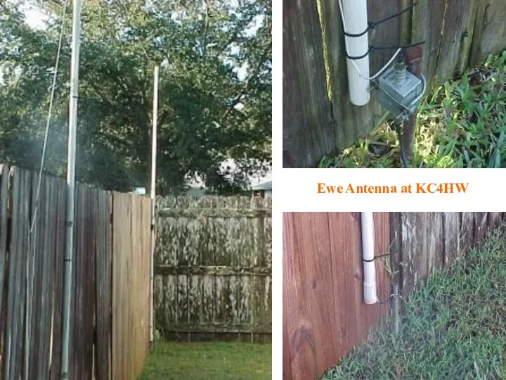
- 21. Ewe Antenna Diagram from ON4UN’s Low Band DXing
- 22. Ewe Antenna at KC4HW
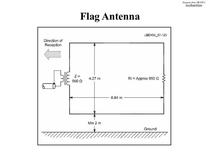
- 23. Flag Antenna Diagram from ON4UN’s Low Band DXing
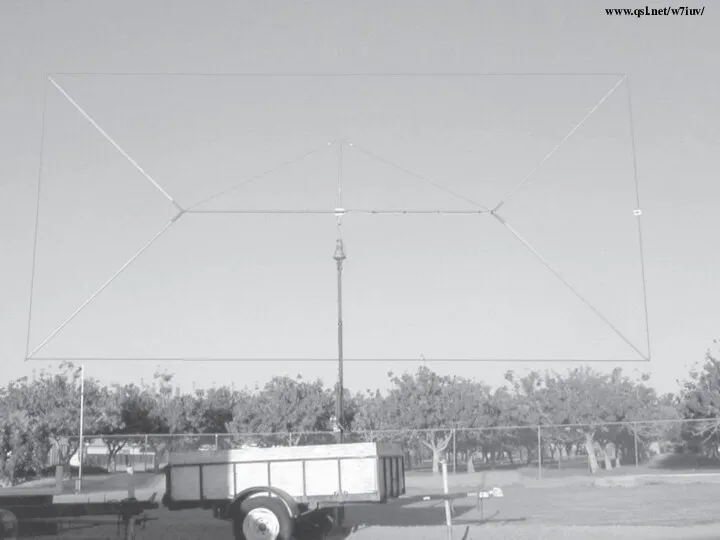
- 24. www.qsl.net/w7iuv/
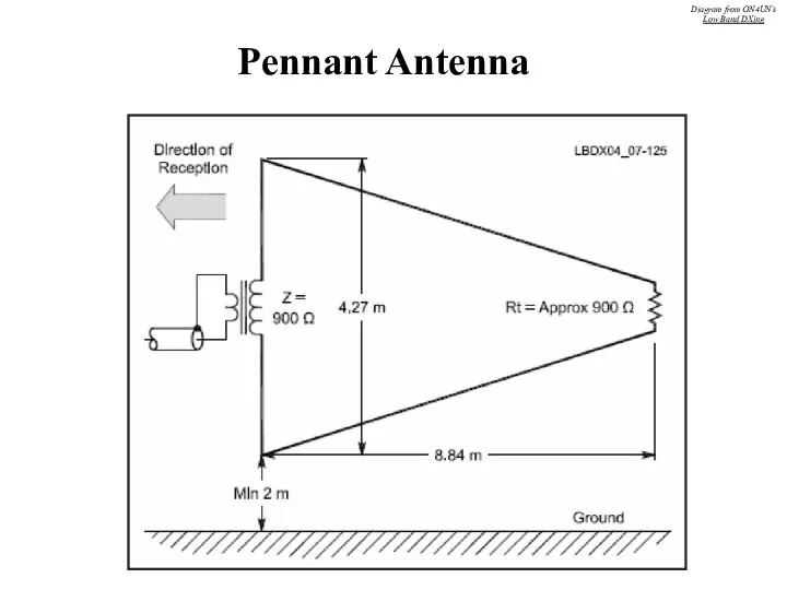
- 25. Pennant Antenna Diagram from ON4UN’s Low Band DXing
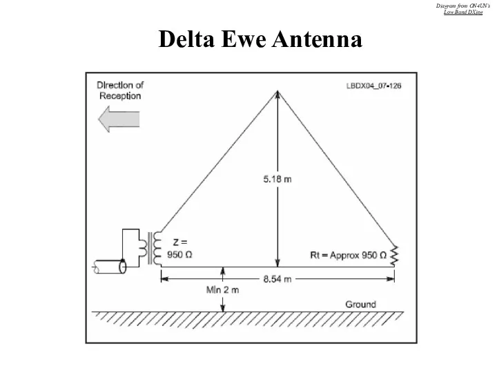
- 26. Delta Ewe Antenna Diagram from ON4UN’s Low Band DXing
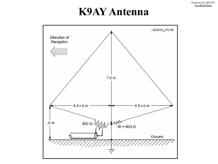
- 27. K9AY Antenna Diagram from ON4UN’s Low Band DXing
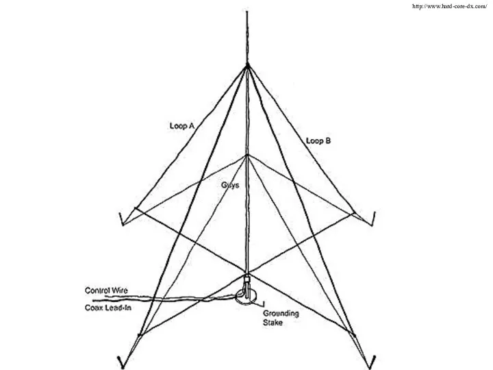
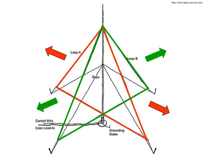
- 28. http://www.hard-core-dx.com/
- 29. http://www.hard-core-dx.com/
- 30. K9AY Switchbox Diagram from ON4UN’s Low Band DXing
- 31. K9AY Control Box Diagram from ON4UN’s Low Band DXing
- 32. Ground Diagram from ON4UN’s Low Band DXing
- 33. Photo from ON4UN’s Low Band DXing
- 34. Diagram from ON4UN’s Low Band DXing
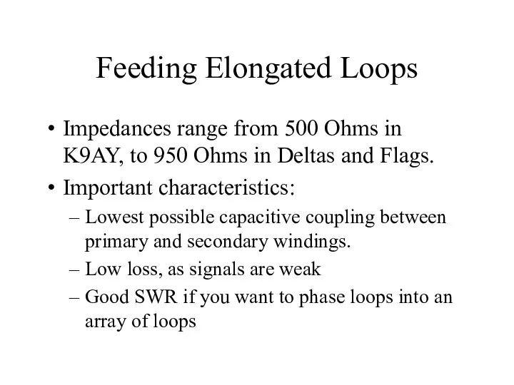
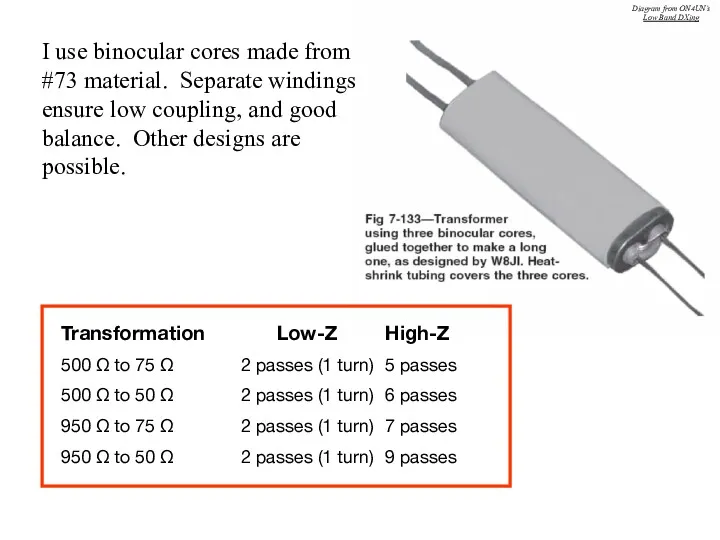
- 35. Feeding Elongated Loops Impedances range from 500 Ohms in K9AY, to 950 Ohms in Deltas and
- 36. Transformation Low-Z High-Z 500 Ω to 75 Ω 2 passes (1 turn) 5 passes 500 Ω
- 37. Diagram from www.w8ji.com
- 38. Elongated Loop Summary Pros Small footprint Simplicity Can be phased to improve performance Much better than
- 39. The Beverage Antenna!
- 41. Diagram from Joseph Carr’s Practical Antenna Handbook
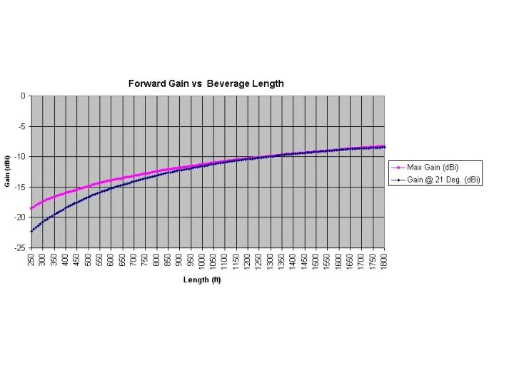
- 42. Influence of Length Following slide shows EZNEC results for a Beverage with following characteristics: 2 meters
- 43. 710 M -4.0 dBi 4.4 wl 535 M -4.7 dBi 3.3 wl 353 M -6.3 dBi
- 45. How High? Not as critical as many think General rule: Higher Beverages produce higher output Higher
- 46. Ground Quality The better the ground, the lower the output Ground quality has little impact on
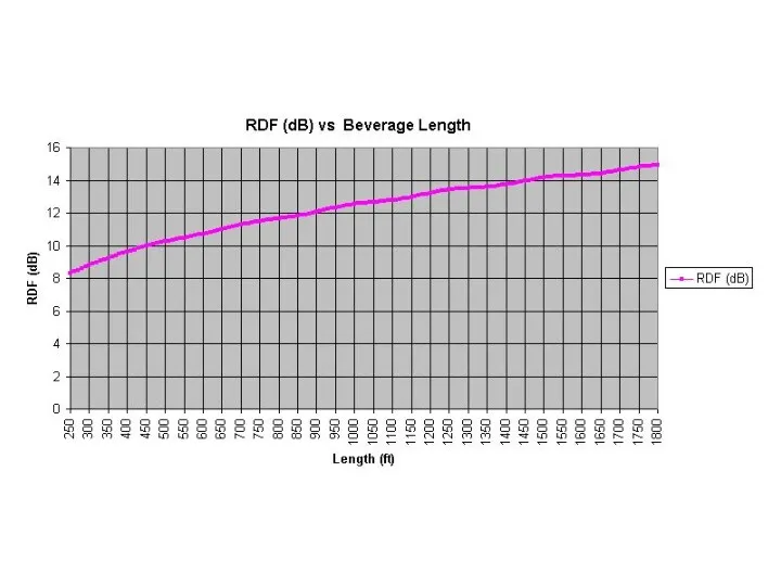
- 47. Gain Curves Radiation Angle Curve Gain and Radiation Angle Diagram from ON4UN’s Low Band DXing
- 48. Wire Inefficient antenna anyway, so size not critical as long as it is physically strong enough
- 49. Theoretical Surge Impedance Z = 138 log 4h d Where: h = height of wire d
- 50. Termination Resistor Should be non-inductive Antenna will pick up TX power and lightning surges, so use
- 51. Photo from www.w8ji.com
- 52. Diagram from ON4UN’s Low Band DXing
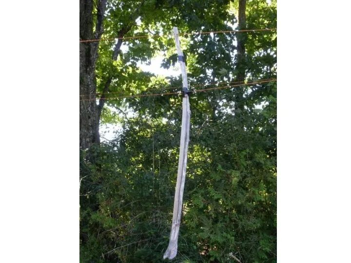
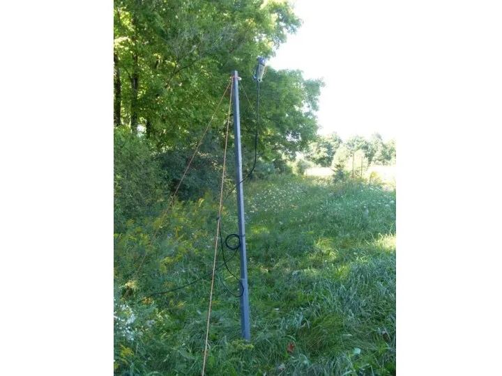
- 53. Supports Metal, non-metallic – doesn’t matter as long as antenna is insulated Poles, fence posts, trees,
- 55. Photo from ON4UN’s Low Band DXing
- 56. Photo from www.w8ji.com
- 57. Photo from www.w8ji.com
- 58. Photo from www.w8ji.com
- 59. Parallel and Crossing Beverages Separate parallel Beverages by distance equal to their height above ground Separate
- 60. Photo from ON4UN’s Low Band DXing
- 62. Matching the Beverage Antenna Several different core material/turns combinations available Separate primary/secondary windings advisable I prefer
- 63. Winding Binocular Cores Pri Sec Pri Z Sec Z Passes Passes Ohm Ohm 4 10 75
- 64. Coax Can use 50 or 75 Ohm cable I prefer 75 Ohm cable Works very well
- 65. Grounds One 8-foot ground rod may suffice Will probably need two or more to stabilize the
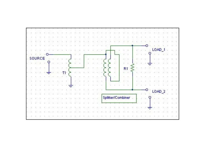
- 66. Multiple Beverages from one Hub Diagram from ON4UN’s Low Band DXing
- 67. Two Directions from one Beverage Diagram from ON4UN’s Low Band DXing
- 68. Another Method… Diagram from ON4UN’s Low Band DXing
- 69. Phasing Beverage Antennas To improve directivity without using long antennas, can phase individual Beverages Two methods:
- 70. Broadside Phasing Narrows frontal lobe Front/Back remains the same Fed in phase Multiband Require wide spacing
- 71. End-Fire Phasing Greatly improves Front/Back directivity Front lobe remains much the same Spacing 5 meters Stagger
- 72. Photo from ON4UN’s Low Band DXing
- 73. Diagrams from ON4UN’s Low Band DXing Broadside Phasing End-Fire Phasing Diagrams from ON4UN’s Low Band DXing
- 74. Crossfire Phasing Simple end-fire feed system developed by W8JI Usable over several octaves Termination value =
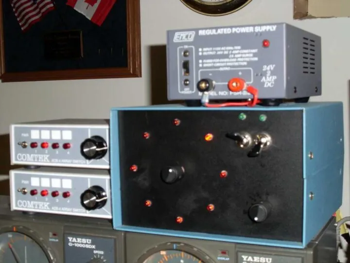
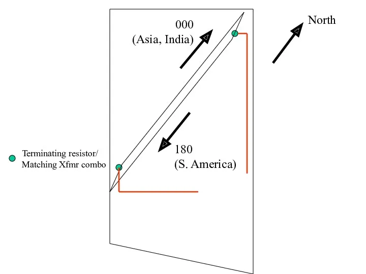
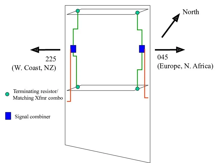
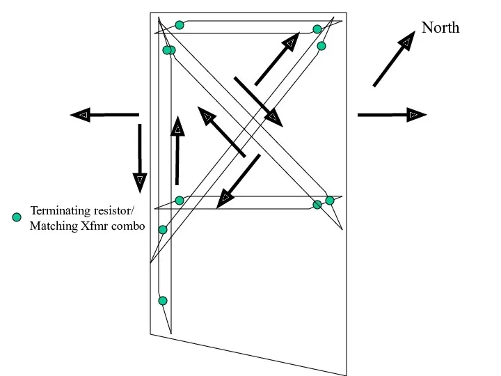
- 75. Beverage Antennas at VO1NO/VE3 5 acres near Merrickville Dimensions ~ 650 x 320 feet 8 directions
- 79. North 000 (Asia, India) 180 (S. America) Terminating resistor/ Matching Xfmr combo
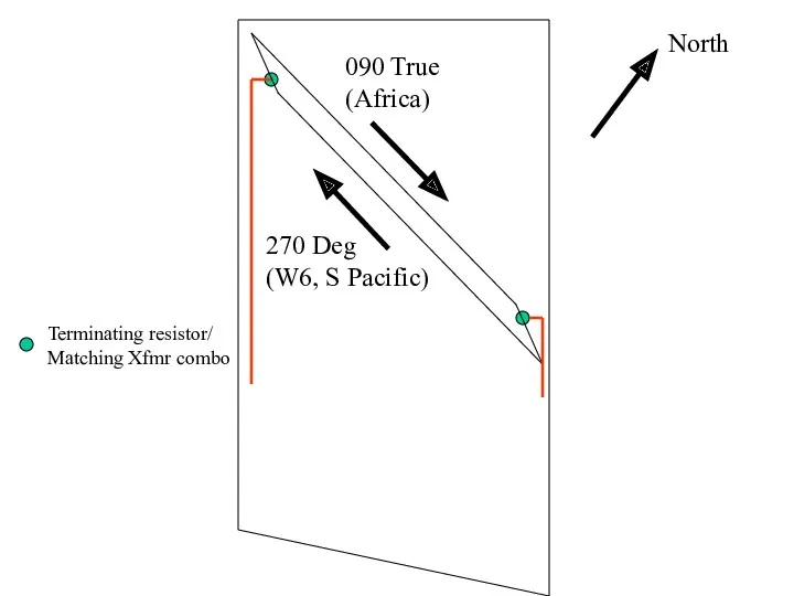
- 80. North 090 True (Africa) 270 Deg (W6, S Pacific) Terminating resistor/ Matching Xfmr combo
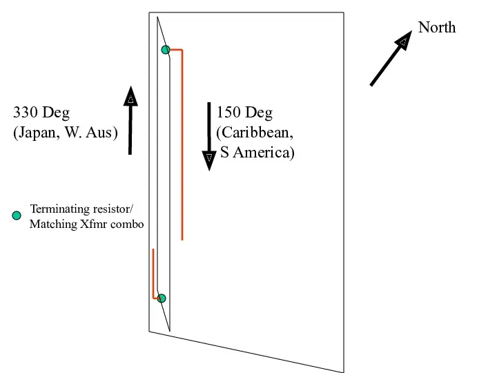
- 81. North 150 Deg (Caribbean, S America) 330 Deg (Japan, W. Aus) Terminating resistor/ Matching Xfmr combo
- 82. North 045 (Europe, N. Africa) 225 (W. Coast, NZ) Terminating resistor/ Matching Xfmr combo Signal combiner
- 83. North Terminating resistor/ Matching Xfmr combo
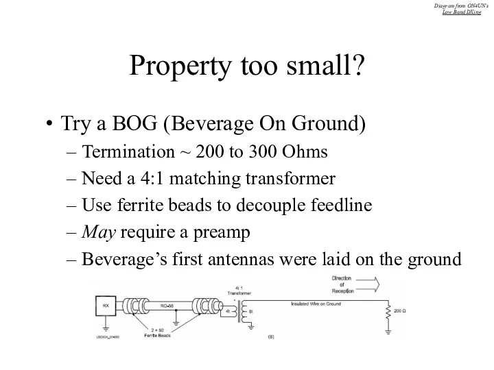
- 84. Property too small? Try a BOG (Beverage On Ground) Termination ~ 200 to 300 Ohms Need
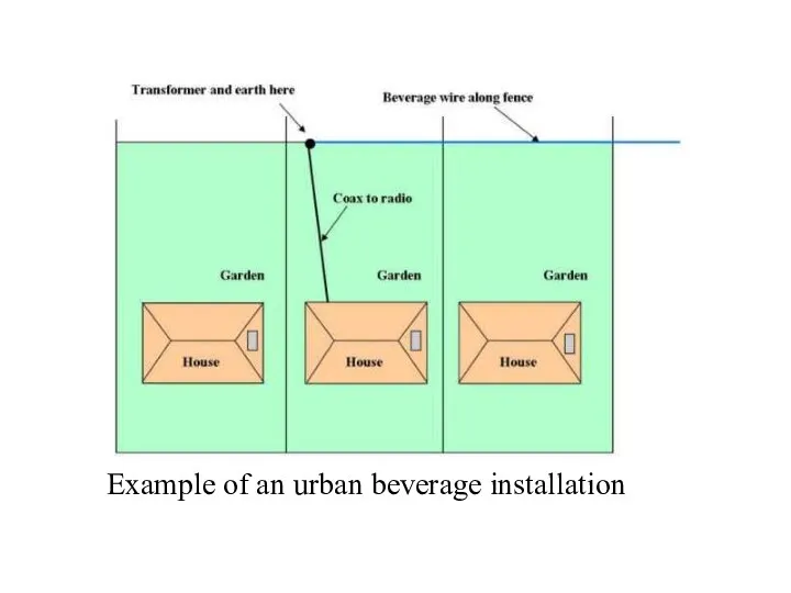
- 85. Example of an urban beverage installation
- 86. For more Information… The “Bible”!! Also check the website of Tom Rauch, W8JI: http://www.w8ji.com Try the
- 87. Questions?
- 99. Скачать презентацию
Tonight’s Topics…
Introduction
Receiving Basics
RX Loops
Elongated Terminated Loops
EWE Antenna
Flag Antenna
Pennant Antenna
K9AY Loop
Beverages
Tonight’s Topics…
Introduction
Receiving Basics
RX Loops
Elongated Terminated Loops
EWE Antenna
Flag Antenna
Pennant Antenna
K9AY Loop
Beverages
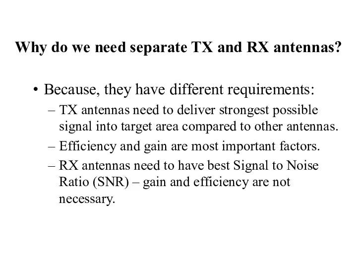
Why do we need separate TX and RX antennas?
Because, they have
Why do we need separate TX and RX antennas?
Because, they have
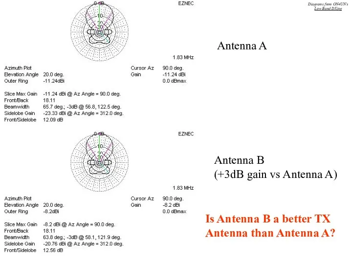
Antenna A
Antenna B
(+3dB gain vs Antenna A)
Is Antenna B a better
Antenna A
Antenna B
(+3dB gain vs Antenna A)
Is Antenna B a better
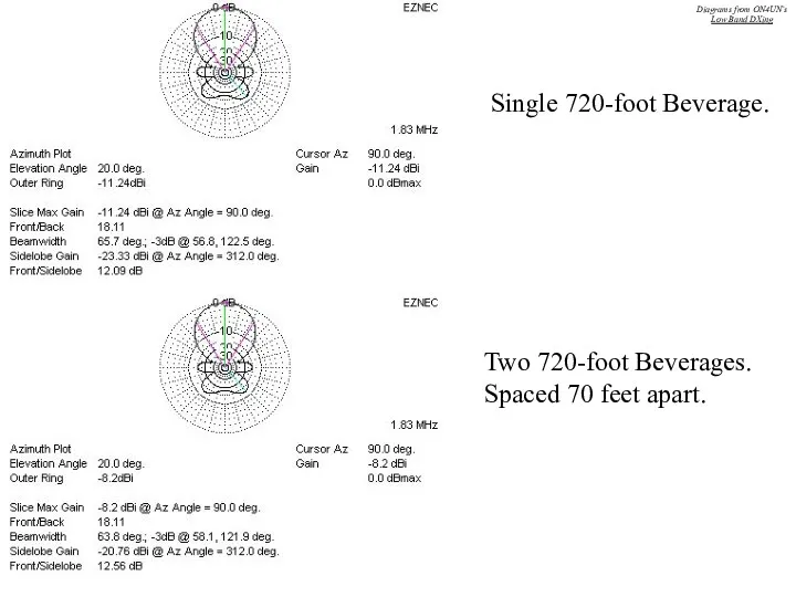
Single 720-foot Beverage.
Two 720-foot Beverages.
Spaced 70 feet apart.
Diagrams from ON4UN’s
Low Band
Single 720-foot Beverage.
Two 720-foot Beverages.
Spaced 70 feet apart.
Diagrams from ON4UN’s
Low Band
Gain single Beverage: -11.2 dBi
Gain two Beverages (70-ft sp): -8.2 dBi
So,
Gain single Beverage: -11.2 dBi
Gain two Beverages (70-ft sp): -8.2 dBi
So,
NO – nothing has been gained!
The pattern is still practically identical
Front/Back
NO – nothing has been gained!
The pattern is still practically identical
Front/Back
How much Negative Gain can we tolerate with RX antennas?
Modern receivers
How much Negative Gain can we tolerate with RX antennas?
Modern receivers
Noise
The sum of all unidentified signals (thunderstorms, man-made, cosmic etc.).
Requires its
Noise
The sum of all unidentified signals (thunderstorms, man-made, cosmic etc.).
Requires its
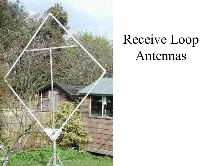
Receive Loop Antennas
Receive Loop Antennas
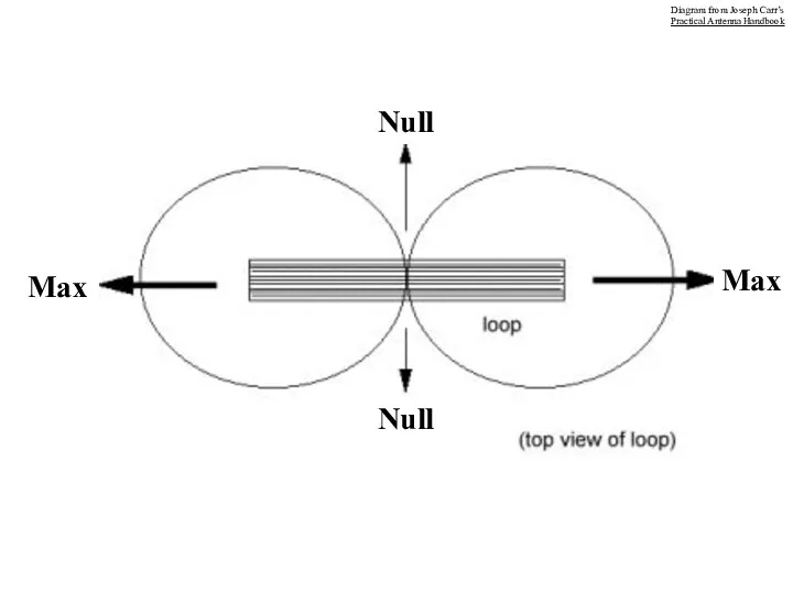
Max
Max
Null
Null
Diagram from Joseph Carr’s
Practical Antenna Handbook
Max
Max
Null
Null
Diagram from Joseph Carr’s
Practical Antenna Handbook
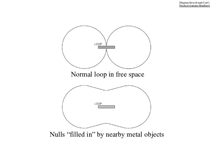
Normal loop in free space
Nulls “filled in” by nearby metal objects
Diagram
Normal loop in free space
Nulls “filled in” by nearby metal objects
Diagram
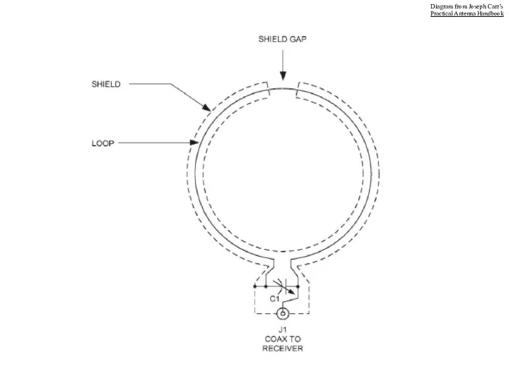
Diagram from Joseph Carr’s
Practical Antenna Handbook
Diagram from Joseph Carr’s
Practical Antenna Handbook
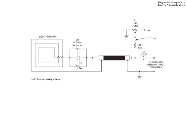
Diagram from Joseph Carr’s
Practical Antenna Handbook
Diagram from Joseph Carr’s
Practical Antenna Handbook
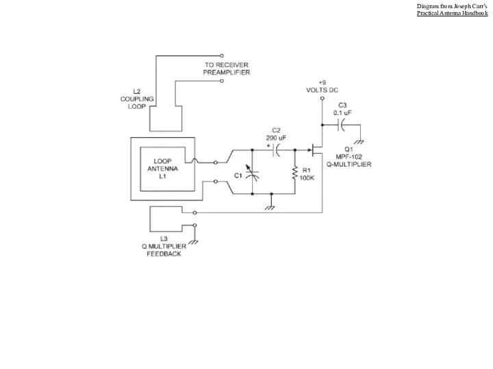
Diagram from Joseph Carr’s
Practical Antenna Handbook
Diagram from Joseph Carr’s
Practical Antenna Handbook
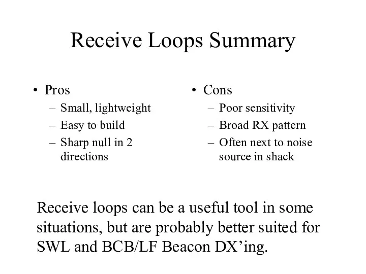
Receive Loops Summary
Pros
Small, lightweight
Easy to build
Sharp null in 2 directions
Cons
Poor sensitivity
Broad
Receive Loops Summary
Pros
Small, lightweight
Easy to build
Sharp null in 2 directions
Cons
Poor sensitivity
Broad
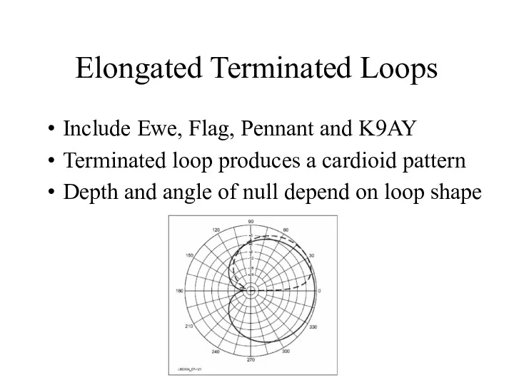
Elongated Terminated Loops
Include Ewe, Flag, Pennant and K9AY
Terminated loop produces a
Elongated Terminated Loops
Include Ewe, Flag, Pennant and K9AY
Terminated loop produces a
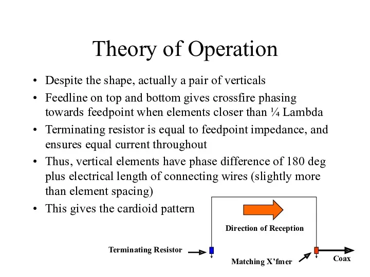
Theory of Operation
Despite the shape, actually a pair of verticals
Feedline
Theory of Operation
Despite the shape, actually a pair of verticals
Feedline
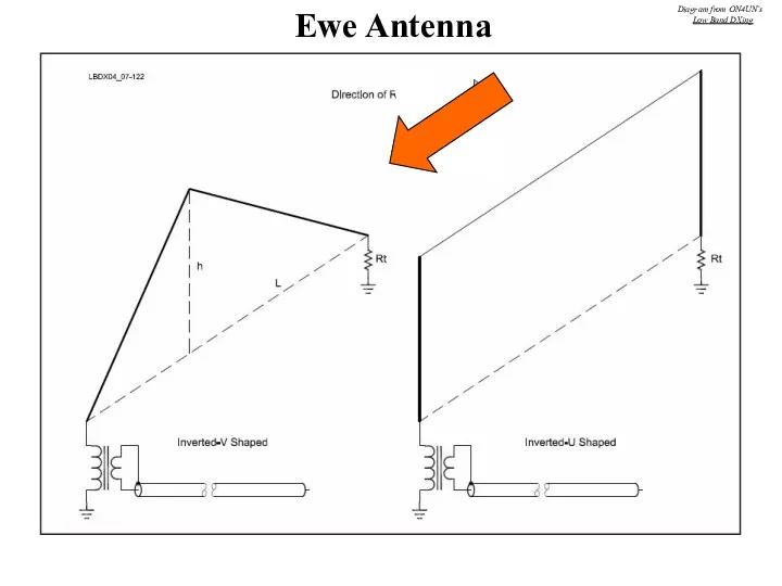
Ewe Antenna
Diagram from ON4UN’s
Low Band DXing
Ewe Antenna
Diagram from ON4UN’s
Low Band DXing
Ewe Antenna at KC4HW
Ewe Antenna at KC4HW
Flag Antenna
Diagram from ON4UN’s
Low Band DXing
Flag Antenna
Diagram from ON4UN’s
Low Band DXing
www.qsl.net/w7iuv/
www.qsl.net/w7iuv/
Pennant Antenna
Diagram from ON4UN’s
Low Band DXing
Pennant Antenna
Diagram from ON4UN’s
Low Band DXing
Delta Ewe Antenna
Diagram from ON4UN’s
Low Band DXing
Delta Ewe Antenna
Diagram from ON4UN’s
Low Band DXing
K9AY Antenna
Diagram from ON4UN’s
Low Band DXing
K9AY Antenna
Diagram from ON4UN’s
Low Band DXing
http://www.hard-core-dx.com/
http://www.hard-core-dx.com/
http://www.hard-core-dx.com/
http://www.hard-core-dx.com/
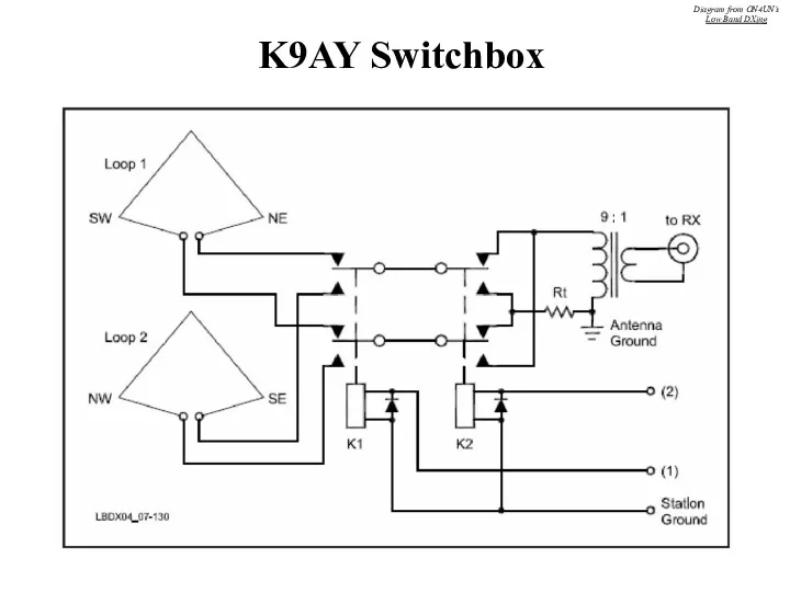
K9AY Switchbox
Diagram from ON4UN’s
Low Band DXing
K9AY Switchbox
Diagram from ON4UN’s
Low Band DXing
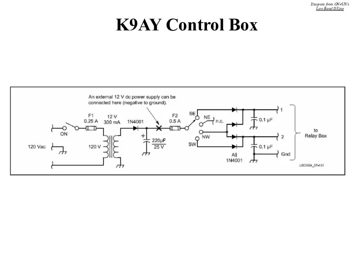
K9AY Control Box
Diagram from ON4UN’s
Low Band DXing
K9AY Control Box
Diagram from ON4UN’s
Low Band DXing
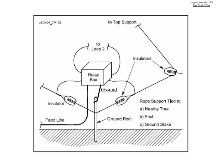
Ground
Diagram from ON4UN’s
Low Band DXing
Ground
Diagram from ON4UN’s
Low Band DXing
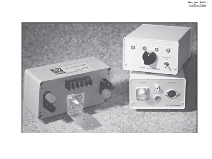
Photo from ON4UN’s
Low Band DXing
Photo from ON4UN’s
Low Band DXing
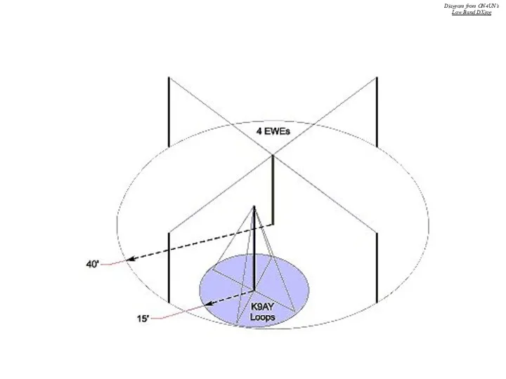
Diagram from ON4UN’s
Low Band DXing
Diagram from ON4UN’s
Low Band DXing
Feeding Elongated Loops
Impedances range from 500 Ohms in K9AY, to 950
Feeding Elongated Loops
Impedances range from 500 Ohms in K9AY, to 950
Transformation Low-Z High-Z
500 Ω to 75 Ω 2 passes (1
500 Ω to 75 Ω 2 passes (1
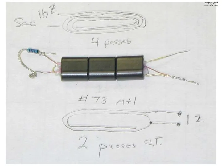
Diagram from
www.w8ji.com
Diagram from
www.w8ji.com
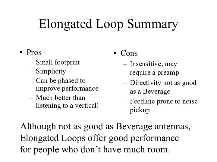
Elongated Loop Summary
Pros
Small footprint
Simplicity
Can be phased to improve performance
Much better than
Elongated Loop Summary
Pros
Small footprint
Simplicity
Can be phased to improve performance
Much better than
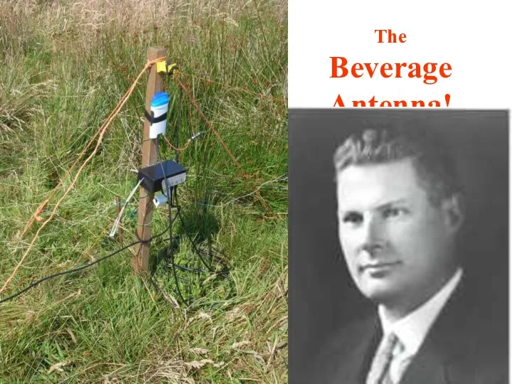
The
Beverage
Antenna!
The
Beverage
Antenna!
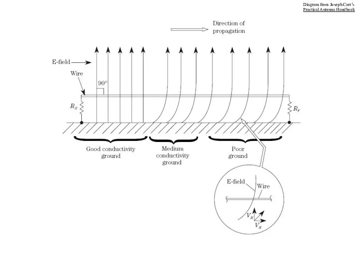
Diagram from Joseph Carr’s
Practical Antenna Handbook
Diagram from Joseph Carr’s
Practical Antenna Handbook
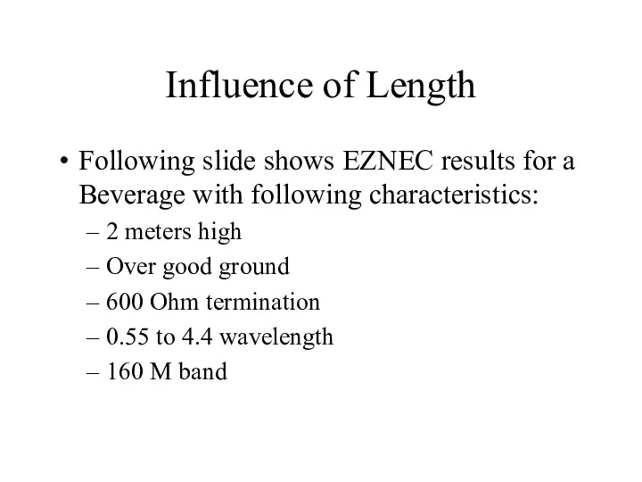
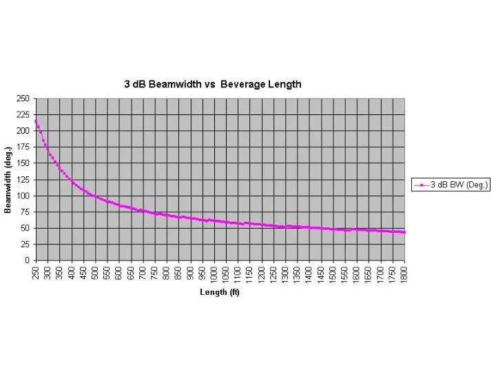
Influence of Length
Following slide shows EZNEC results for a Beverage with
Influence of Length
Following slide shows EZNEC results for a Beverage with
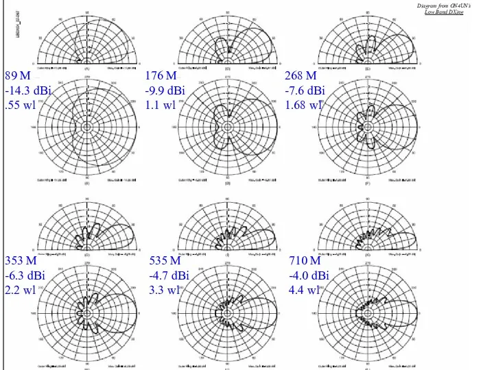
710 M
-4.0 dBi
4.4 wl
535 M
-4.7 dBi
3.3 wl
353 M
-6.3 dBi
2.2 wl
268 M
-7.6
710 M
-4.0 dBi
4.4 wl
535 M
-4.7 dBi
3.3 wl
353 M
-6.3 dBi
2.2 wl
268 M
-7.6
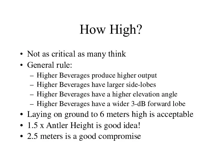
How High?
Not as critical as many think
General rule:
Higher Beverages produce higher
How High?
Not as critical as many think
General rule:
Higher Beverages produce higher
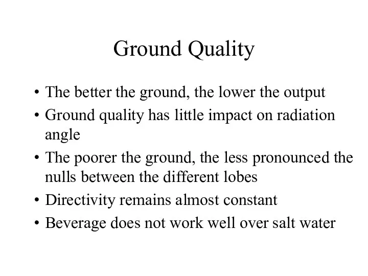
Ground Quality
The better the ground, the lower the output
Ground quality has
Ground Quality
The better the ground, the lower the output
Ground quality has
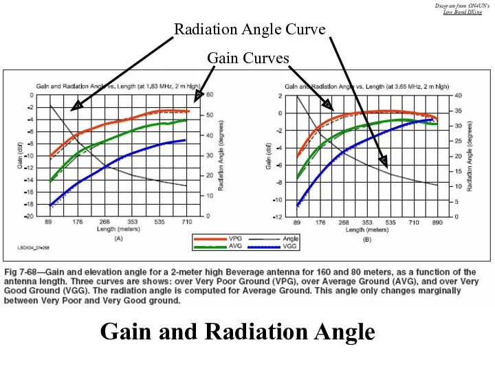
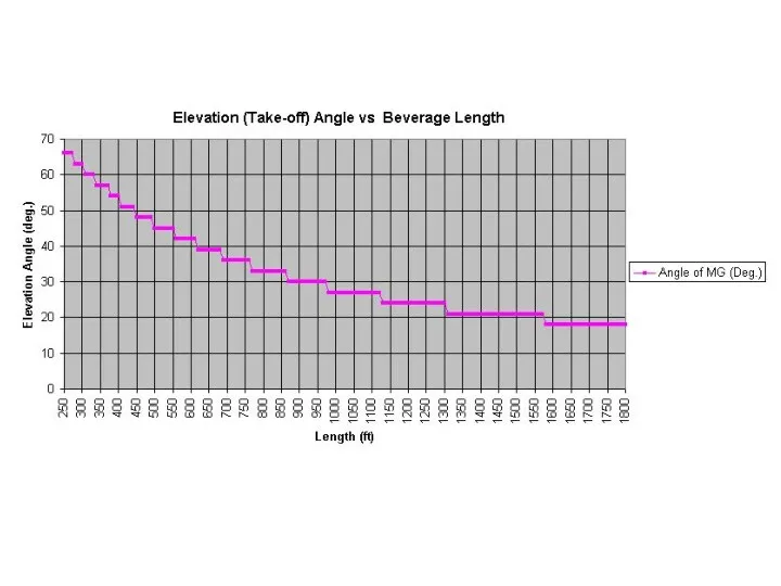
Gain Curves
Radiation Angle Curve
Gain and Radiation Angle
Diagram from ON4UN’s
Low Band DXing
Gain Curves
Radiation Angle Curve
Gain and Radiation Angle
Diagram from ON4UN’s
Low Band DXing
Wire
Inefficient antenna anyway, so size not critical as long as it
Wire
Inefficient antenna anyway, so size not critical as long as it
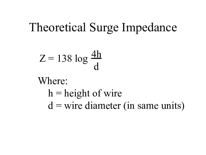
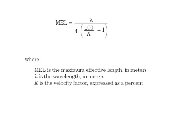
Theoretical Surge Impedance
Z = 138 log
4h
d
Where:
h = height of wire
d
Theoretical Surge Impedance
Z = 138 log
4h
d
Where:
h = height of wire
d
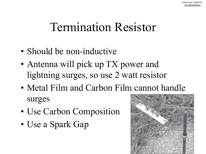
Termination Resistor
Should be non-inductive
Antenna will pick up TX power and lightning
Termination Resistor
Should be non-inductive
Antenna will pick up TX power and lightning
Photo from www.w8ji.com
Photo from www.w8ji.com
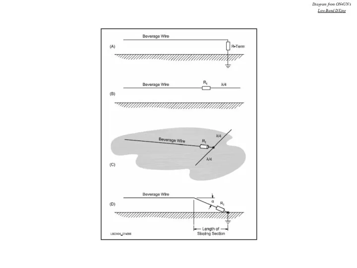
Diagram from ON4UN’s
Low Band DXing
Diagram from ON4UN’s
Low Band DXing
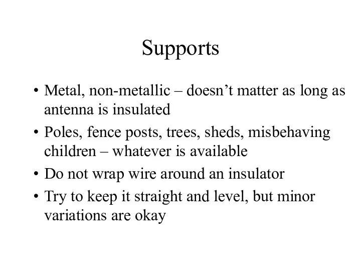
Supports
Metal, non-metallic – doesn’t matter as long as antenna is insulated
Poles,
Supports
Metal, non-metallic – doesn’t matter as long as antenna is insulated
Poles,
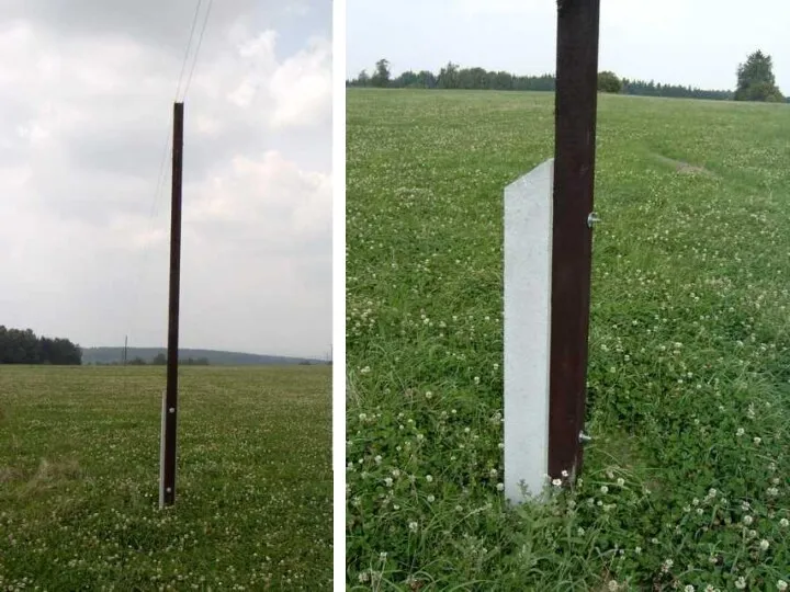
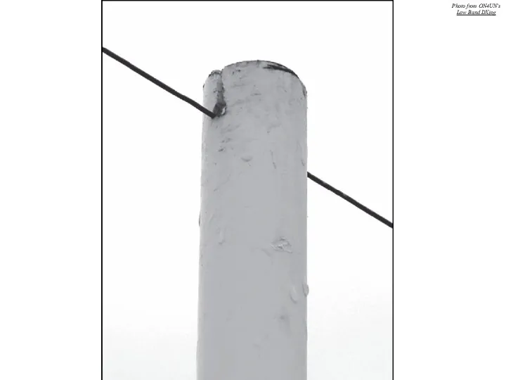
Photo from ON4UN’s
Low Band DXing
Photo from ON4UN’s
Low Band DXing
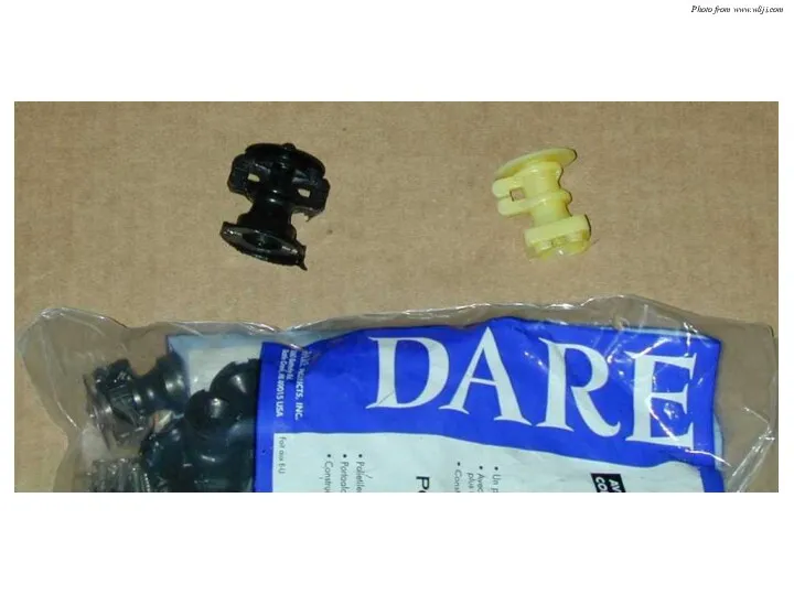
Photo from www.w8ji.com
Photo from www.w8ji.com
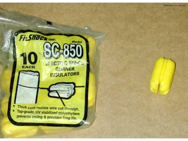
Photo from www.w8ji.com
Photo from www.w8ji.com
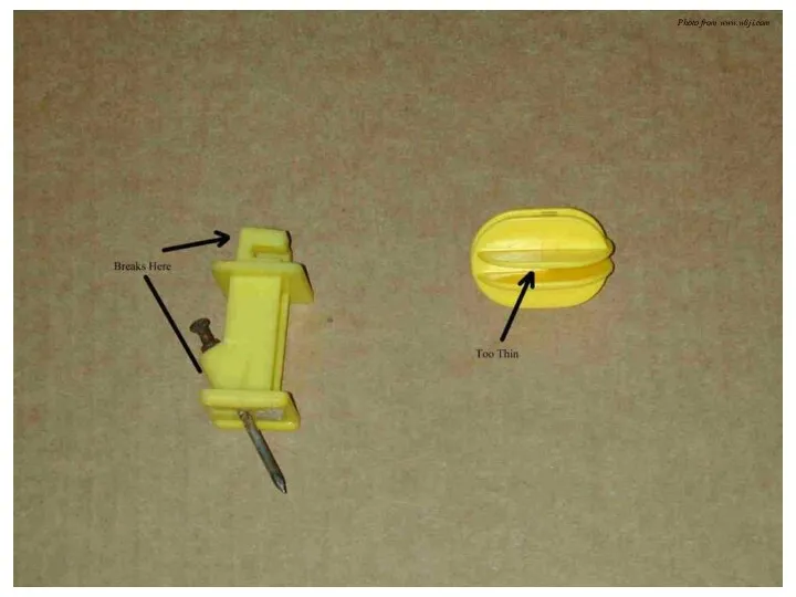
Photo from www.w8ji.com
Photo from www.w8ji.com
Parallel and Crossing Beverages
Separate parallel Beverages by distance equal to their
Parallel and Crossing Beverages
Separate parallel Beverages by distance equal to their
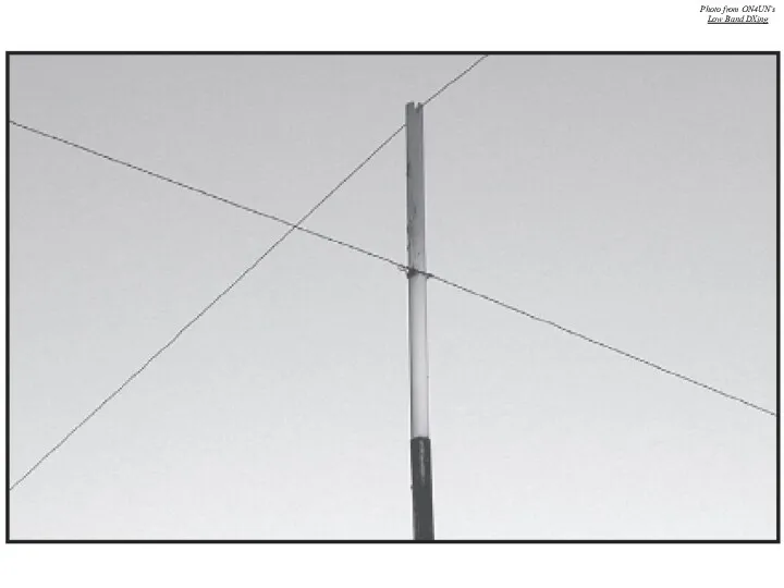
Photo from ON4UN’s
Low Band DXing
Photo from ON4UN’s
Low Band DXing
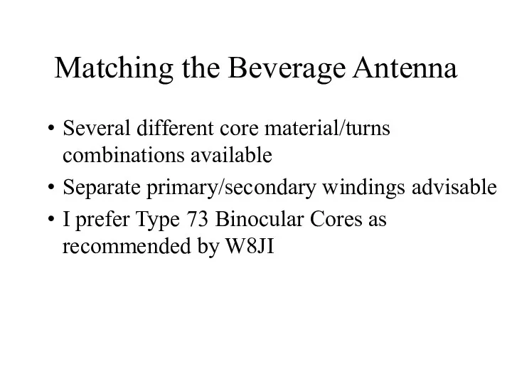
Matching the Beverage Antenna
Several different core material/turns combinations available
Separate primary/secondary windings
Matching the Beverage Antenna
Several different core material/turns combinations available
Separate primary/secondary windings
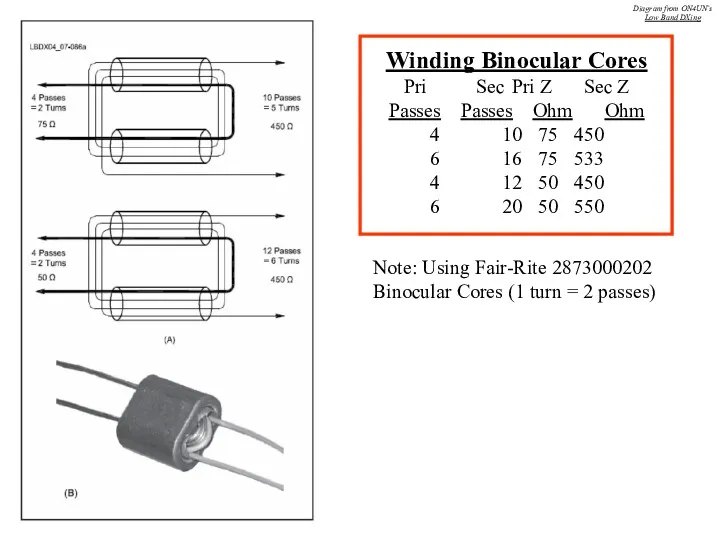
Winding Binocular Cores
Pri Sec Pri Z Sec Z
Passes Passes Ohm Ohm
4 10 75 450
6 16 75 533
4 12 50 450
6 20 50 550
Note: Using Fair-Rite 2873000202
Binocular Cores (1 turn
Winding Binocular Cores
Pri Sec Pri Z Sec Z
Passes Passes Ohm Ohm
4 10 75 450
6 16 75 533
4 12 50 450
6 20 50 550
Note: Using Fair-Rite 2873000202
Binocular Cores (1 turn
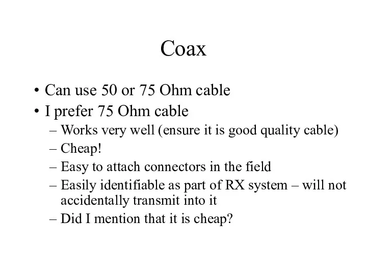
Coax
Can use 50 or 75 Ohm cable
I prefer 75 Ohm cable
Works
Coax
Can use 50 or 75 Ohm cable
I prefer 75 Ohm cable
Works
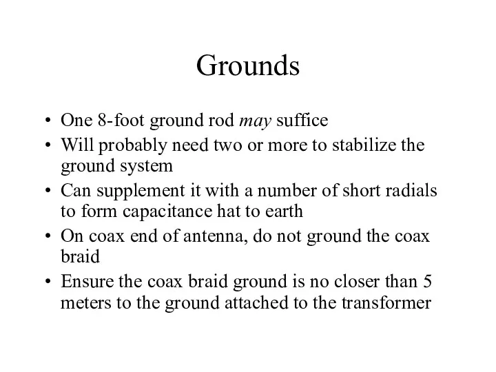
Grounds
One 8-foot ground rod may suffice
Will probably need two or more
Grounds
One 8-foot ground rod may suffice
Will probably need two or more
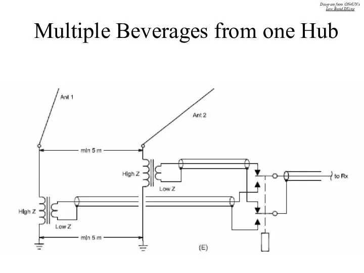
Multiple Beverages from one Hub
Diagram from ON4UN’s
Low Band DXing
Multiple Beverages from one Hub
Diagram from ON4UN’s
Low Band DXing
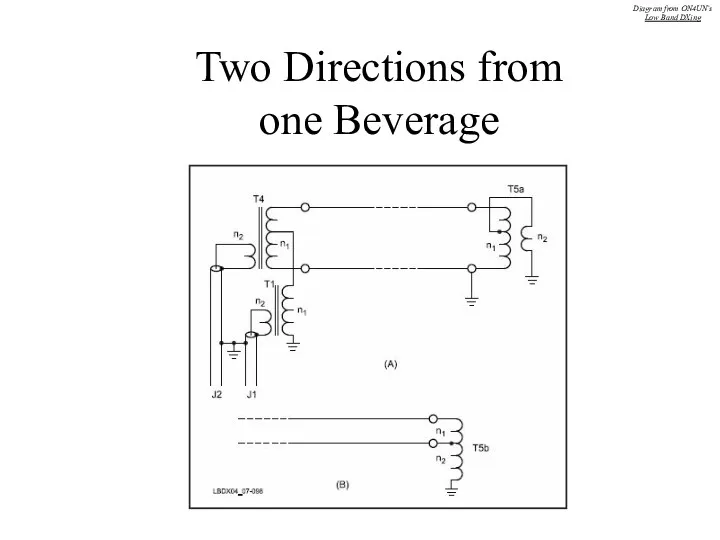
Two Directions from
one Beverage
Diagram from ON4UN’s
Low Band DXing
Two Directions from
one Beverage
Diagram from ON4UN’s
Low Band DXing
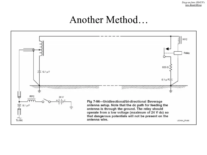
Another Method…
Diagram from ON4UN’s
Low Band DXing
Another Method…
Diagram from ON4UN’s
Low Band DXing
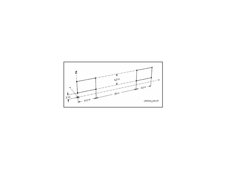
Phasing Beverage Antennas
To improve directivity without using long antennas, can phase
Phasing Beverage Antennas
To improve directivity without using long antennas, can phase
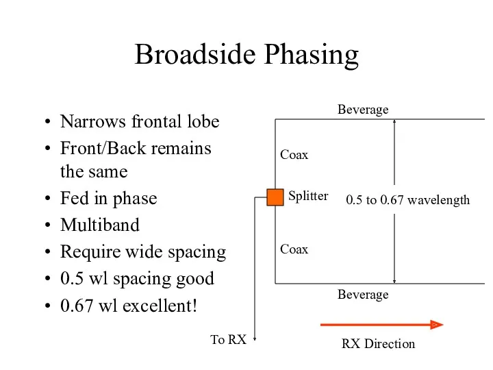
Broadside Phasing
Narrows frontal lobe
Front/Back remains the same
Fed in phase
Multiband
Require wide spacing
0.5
Broadside Phasing
Narrows frontal lobe
Front/Back remains the same
Fed in phase
Multiband
Require wide spacing
0.5
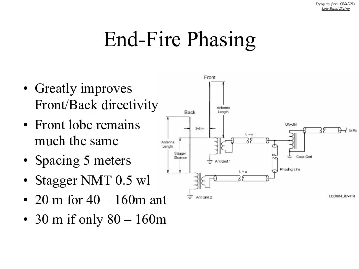
End-Fire Phasing
Greatly improves Front/Back directivity
Front lobe remains much the same
Spacing 5
End-Fire Phasing
Greatly improves Front/Back directivity
Front lobe remains much the same
Spacing 5
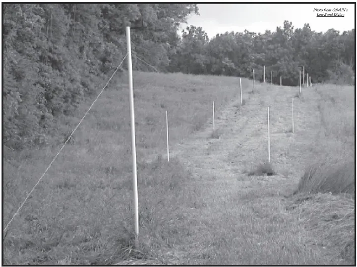
Photo from ON4UN’s
Low Band DXing
Photo from ON4UN’s
Low Band DXing
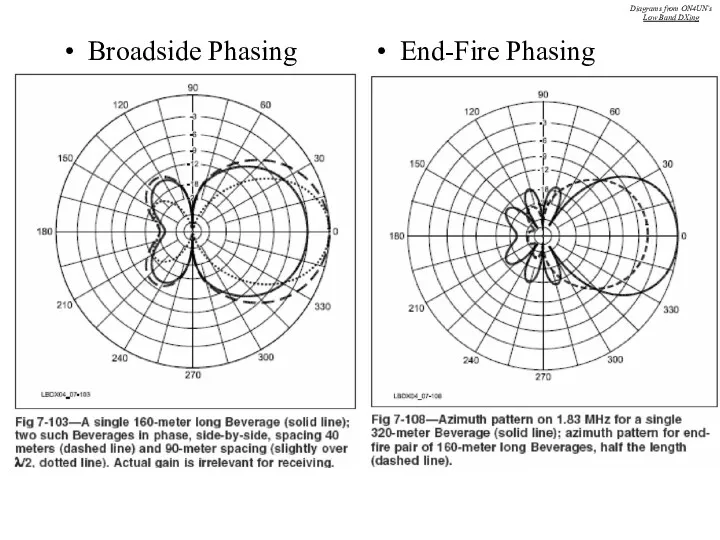
Diagrams from ON4UN’s
Low Band DXing
Broadside Phasing
End-Fire Phasing
Diagrams from ON4UN’s
Low Band DXing
Diagrams from ON4UN’s
Low Band DXing
Broadside Phasing
End-Fire Phasing
Diagrams from ON4UN’s
Low Band DXing
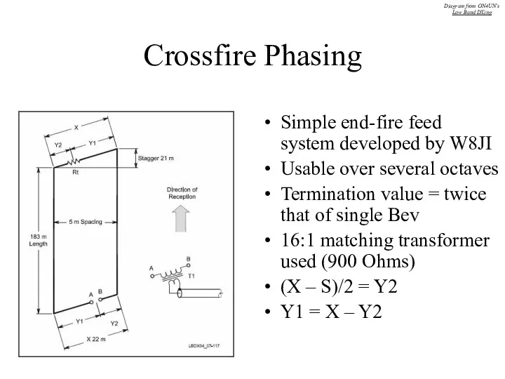
Crossfire Phasing
Simple end-fire feed system developed by W8JI
Usable over several octaves
Termination
Crossfire Phasing
Simple end-fire feed system developed by W8JI
Usable over several octaves
Termination
Beverage Antennas at VO1NO/VE3
5 acres near Merrickville
Dimensions ~ 650 x 320
Beverage Antennas at VO1NO/VE3
5 acres near Merrickville
Dimensions ~ 650 x 320
North
000
(Asia, India)
180
(S. America)
Terminating resistor/
Matching Xfmr combo
North
000
(Asia, India)
180
(S. America)
Terminating resistor/
Matching Xfmr combo
North
090 True
(Africa)
270 Deg
(W6, S Pacific)
Terminating resistor/
Matching Xfmr combo
North
090 True
(Africa)
270 Deg
(W6, S Pacific)
Terminating resistor/
Matching Xfmr combo
North
150 Deg
(Caribbean,
S America)
330 Deg
(Japan, W. Aus)
Terminating resistor/
Matching Xfmr combo
North
150 Deg
(Caribbean,
S America)
330 Deg
(Japan, W. Aus)
Terminating resistor/
Matching Xfmr combo
North
045
(Europe, N. Africa)
225
(W. Coast, NZ)
Terminating resistor/
Matching Xfmr combo
Signal combiner
North
045
(Europe, N. Africa)
225
(W. Coast, NZ)
Terminating resistor/
Matching Xfmr combo
Signal combiner
North
Terminating resistor/
Matching Xfmr combo
North
Terminating resistor/
Matching Xfmr combo
Property too small?
Try a BOG (Beverage On Ground)
Termination ~ 200 to
Property too small?
Try a BOG (Beverage On Ground)
Termination ~ 200 to
Example of an urban beverage installation
Example of an urban beverage installation

For more Information…
The “Bible”!!
Also check the website of Tom Rauch, W8JI:
http://www.w8ji.com
Try
For more Information…
The “Bible”!!
Also check the website of Tom Rauch, W8JI:
http://www.w8ji.com
Try

Questions?
Questions?


 Хронология основных открытий в области квантовой механики, атомной и ядерной физики
 Молекулярная физика
 Система Motronic. Die Motronic
 Кинематический анализ плоских стержневых конструкций
 Делительные головки
 Выставка удивительных вещей (Шуточная экспозиция на физическую тему)
 Лампы накаливание против энергосберегающих
 Интеллектуальный марафон
 урок №3 источники физических знаний
 Внеклассное мероприятие по физике Чернобыльская АЭС
 Физика. Сила
 Ременная передача
 Восстановление деталей пайкой
 Расчёт погрешностей результатов экспериментов
 Презентация к уроку: Физика и дорожная безопасность
 Массообменные процессы
 Взаимодействие быстрых электронов с веществом (часть 1)
 Изменение агрегатных состояний вещества
 Лекция 22 (5). Строение атома
 Бірқалыпты үдемелі қозғалыс. Үдеу
 Связь физики с профессией
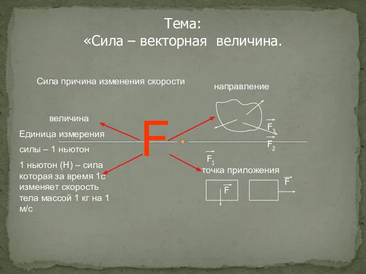 Сила – векторная величина
 Внеклассные мероприятия по физике.
 Кинематика. Основные понятия кинематики
 Загальні відомості про рух
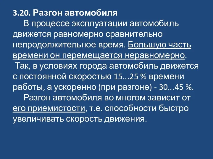 Разгон автомобиля
 Látka a teplo. Výpočet tepla
 Работа и мощность электрического тока. Единицы работы электрического тока