- Maintenance Level Training. TA 400 Tier 2/4 – Scania Engine

Содержание
- 2. Bore x Stroke 130 x 140 mm HP Range 401 - 550 HP Displacement 12.7 lt.
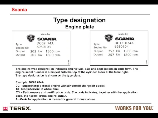
- 3. Type designation Engine plate The engine type designation indicates engine type, size and applications in code
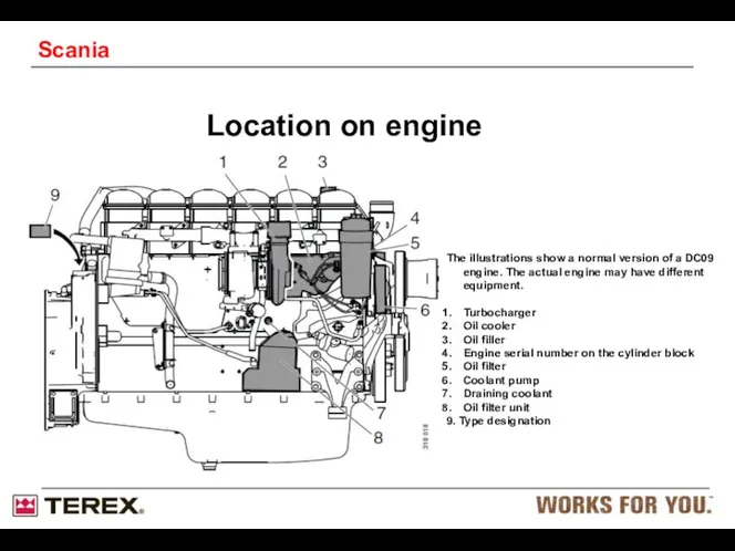
- 4. Location on engine The illustrations show a normal version of a DC09 engine. The actual engine
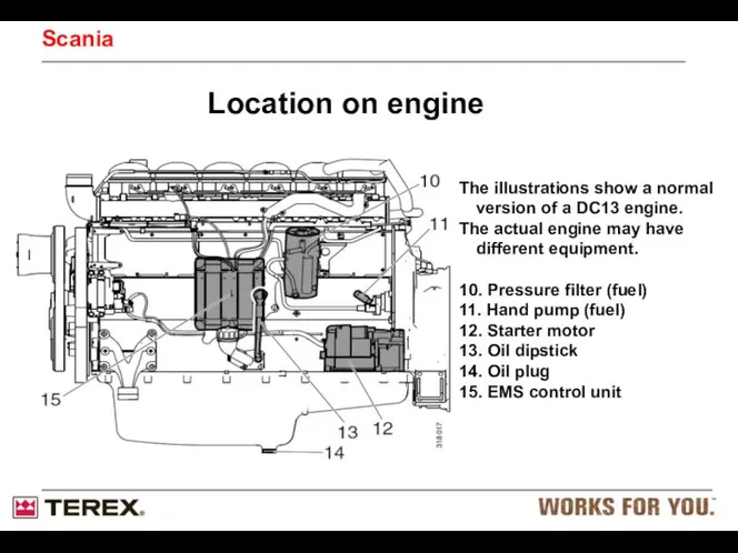
- 5. Location on engine Scania The illustrations show a normal version of a DC13 engine. The actual
- 6. Maintenance first 500 h. Check/Adjust valve clearance and PDE height Change oil and oil filter (cartridge
- 7. Inspection interval 1 =More often if required
- 8. Checking the oil level Daily Oil dipstick Oil filler cap Scania
- 9. Changing the oil Every 500 hours Scania
- 10. Low CO2 emissions High outputs Response Sulphur level in fuel Cooling demand Prepared for Stage 4
- 11. Selective Catalytic Reduction, SCR Warning! When the engine is running the exhaust system parts can reach
- 12. Selective Catalytic Reduction SCR Scania Overview of the system. The system contains a tank with pump
- 13. SCR System Scania Legal demand Max 10 PPM Sulfur Technical limit 300PPM
- 14. Exhaust Emissions Diesel exhaust gases contains (legislated emissions): Nitrogen Oxides, NOx Hydro Carbons, HC Carbon Monoxide,
- 15. What is Urea? Pure urea is in the form of white crystals Urea dissolved in water
- 16. Location of engine speed sensors on the engine with EMS S6. The detail shows some of
- 17. Engine speed sensors (2x) Location on engine There are two engine speed sensors in the EMS
- 18. SCR Catalysts working temp Exhaust temp > 200°C necessary Good function above 250°C Maximum function from
- 19. Hydrolysis catalyst Hydrolysis catalyst with dosing unit Dosing unit cooled by urea reductant Injection stop when
- 20. SCR catalyst with Silencer Damping approx 20 dB(A) Only for DC9 and DC13 Outlet can be
- 21. NOx flange NOx flange is mandatory The flange is needed to uniform the exhaust flow for
- 22. Ambient condition sensor Needed as a reference sensor to EMS Only valid for SCR engines Fitted
- 23. DEF tank Scania Maximum constant temperature of urea 50°C Do not fit filler neck expansion room
- 24. Red arrow water Blue arrow urea Filter SCR tank module flow SCR pick up unit Scania
- 25. Fitting of the NOx control unit on exhaust cradle Electrical cable length between sensor and control
- 26. Important Make sure that you always clean the area when working on the SCR system to
- 27. Components in the SCR-system 2.Coolant valve 3.Temperature sensor 4.Level and temperature sensor in reductant tank 5.Electrically
- 28. Control unit EEC3 (E67) The EEC3 control unit retrieves data from the system's sensors and components.
- 29. NOx sensor (T115) NOx sensor (T115) There is a NOx sensor in the system. It is
- 30. Exhaust temperature sensor before catalytic converter (T113) Temperature sensor (T113) There is a temperature sensor for
- 31. Level sensor and temperature sensor (T116) Pipe for coolant Level sensor Temperature sensor Level sensor and
- 32. Reductant pump (V183) Reductant pump (V183) To achieve the right reductant pressure prior to metering in
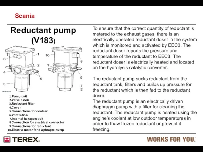
- 33. Reductant pump (V183) To ensure that the correct quantity of reductant is metered to the exhaust
- 34. Reductant pump (V183) Intake, reductant Outlet, reductant Prefilter, reductant Antifreeze Overflow valve Port to pump chamber
- 35. Reductant pump (V183) Port from prefilter Intake valve Pump diaphragm Outlet valve Port to reductant filter
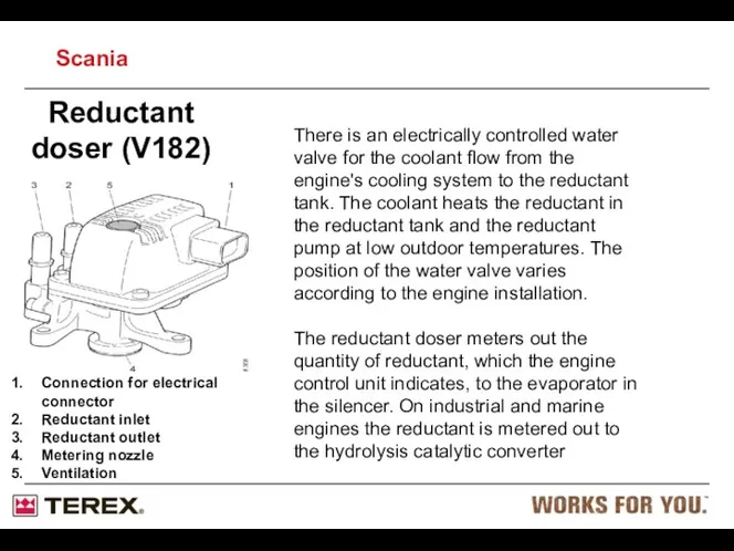
- 36. Reductant doser (V182) Connection for electrical connector Reductant inlet Reductant outlet Metering nozzle Ventilation There is
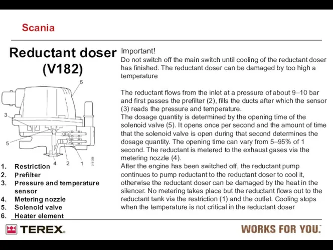
- 37. Reductant doser (V182) Restriction Prefilter Pressure and temperature sensor Metering nozzle Solenoid valve Heater element .
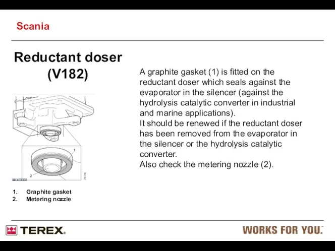
- 38. Reductant doser (V182) Graphite gasket Metering nozzle A graphite gasket (1) is fitted on the reductant
- 39. Coolant valve (V118) Coolant valve (V118) There is an electrically controlled water valve for the coolant
- 40. Electrically heated hoses for reductant (H25, H26,) The hoses designed for reductant are electrically heated in
- 41. System overview for electrics The locations of components vary depending on the engine version and installation.
- 42. System overview for mechanics Reductant Tank Coolant hoses Engine Hydrolysis Catalyst SCR Catalyst Scania
- 43. Reductant filter Antifreeze Reductant filter The illustration shows the reductant filter (1) facing upwards. The reductant
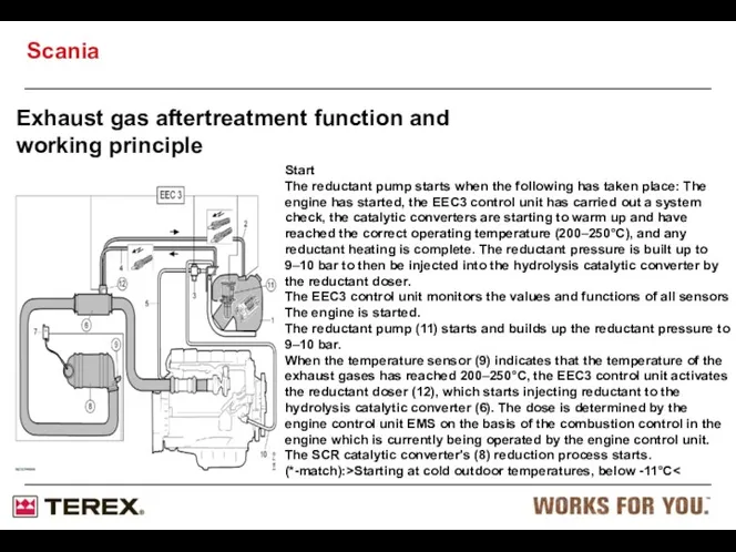
- 44. Exhaust gas aftertreatment function and working principle Start The reductant pump starts when the following has
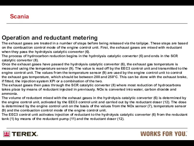
- 45. Operation and reductant metering The exhaust gases are treated in a number of steps before being
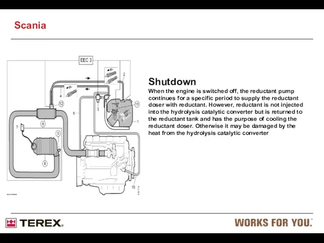
- 46. Shutdown When the engine is switched off, the reductant pump continues for a specific period to
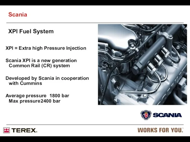
- 47. XPI = Extra high Pressure Injection Scania XPI is a new generation Common Rail (CR) system
- 48. Historical overwiew Unit injector systems = high pressure generated in each injector Injection pressure is a
- 49. Benefits from Scania XPI Injection timing or duration independent of camshaft position Higher average injection pressure
- 50. Scania XPI common-rail fuel system All speed engine Stage 3B/Tier 4i Scania
- 51. Injector w/ Electronically Controlled Pilot Valve (Only 1 Shown) Low Pressure Pump High Pressure Pump Accumulator
- 52. Fuel Connections XPI Scania
- 53. Scania XPI High Pressure Connectors Fuel Manifold Fuel Heater 350W 5-24 deg Hand Pump Inlet Metering
- 54. Fuel tank Hand pump with check valves Fuel filter, water separating suction filter Control unit cooler
- 55. Working principle of Scania XPI Fuel is sucked from the tank by the low-pressure pump via
- 56. High Pressure Low Pressure Return Flow Scania
- 57. Venturi housing Inlet from low pressure pump Inlet from return manifold Return to the fuel tank
- 58. Mesh filter The pressurized inlet to the Venturi housing is protected by a wire mesh filter.
- 59. XPI HPP, Cut away view IMV Inlet metering valve LPP Low pressure pump Camshaft Inlet fuel
- 60. XPI HPP Head Assembly Outlet checkvalve Inlet checkvalve Barrel Seal washer 2-bump camshaft Plunger lift roller
- 61. XPI Barrel Design “1-pce” bbl (externally threaded) seal washer o-ring Scania
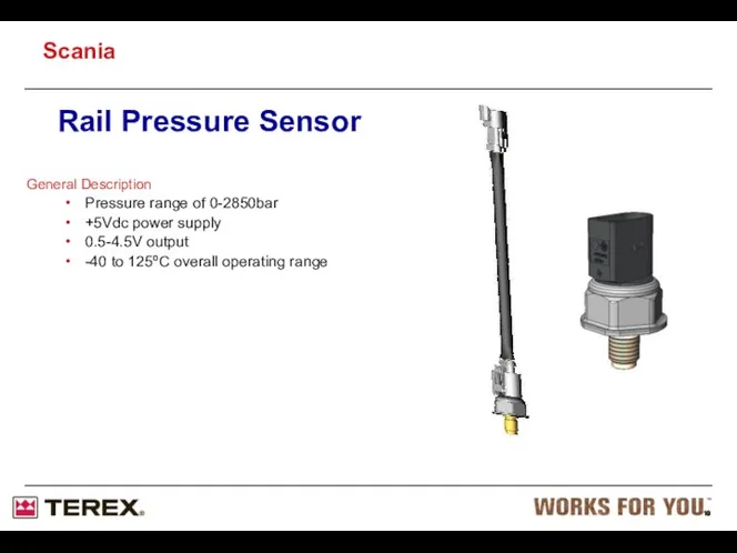
- 62. Rail Pressure Sensor General Description Pressure range of 0-2850bar +5Vdc power supply 0.5-4.5V output -40 to
- 63. General Description Pressure range of 0-2850bar +5Vdc power supply 0.5-4.5V output -40 to 125ºC overall operating
- 64. Accumulator Accumulator chamber High pressure line connections Mechanical dump valve (safety valve) Fuel pressure sensor connection
- 65. Dual-Stage Safety valve: Cone-on-Cone on 1st Stage Cone-on-Cone on 2nd Stage Spring Retainer O-Ring Shim Spring
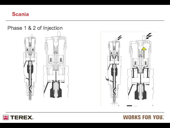
- 66. XPI Injector Injector Scania XPI Function Phase 1, no power to the solenoid valve in the
- 67. Phase 1 & 2 of Injection Scania
- 68. = High pressure Fuel = Return Fuel Scania
- 69. Injectors: Individual adjustment code Each injector has an individual adjustment code. This code has to be
- 70. Multiple injections Multiple injections are possible with this electronically controlled injection system. (A small amount of
- 71. Injector assembly High Pressure Connector Injector clamp High Pressure Line Scania
- 72. Cleanliness requirement Many internal parts in the system are sensitive to dirt and water droplets. This
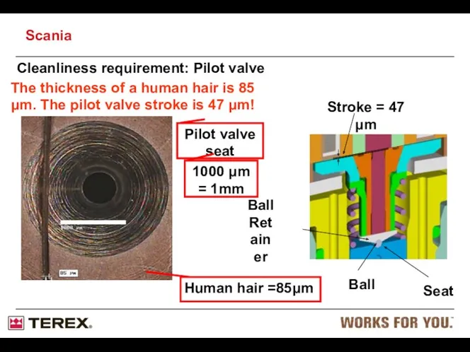
- 73. Cleanliness requirement: Pilot valve Seat Scania
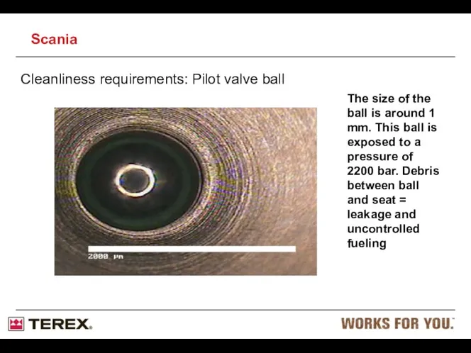
- 74. Cleanliness requirements: Pilot valve ball The size of the ball is around 1 mm. This ball
- 75. Cleanliness requirement: General Do not use compressed air for cleaning purposes. Use only non-fluffy cleaning cloths
- 76. Service: Safety Due to the high fuel pressure, leakage can cause jets of fuel that penetrates
- 77. S8 Engine Management System (EMS) The S8 EMS is introduced with improved memory addressing, and is
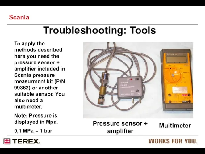
- 78. Troubleshooting: Tools To apply the methods described here you need the pressure sensor + amplifier included
- 79. If engine is not firing at all: Start with checking the feedpressure from the LPP. Connect
- 80. If the railpressure is too low (fault code for low railpressure triggered): Begin with checking all
- 81. Fuel system, PDE (Pumpe-Düse-Einheit) Scania
- 82. Fuel system Fuel rail Fuel rail Drain nipple (for bleeding) Fuel filter Overflow valve 3 4
- 83. Fuel system Fuel flow, Monorail Scania
- 84. Fuel system Skeleton diagram of the fuel system 1. Feed pump 2. Hand pump 3. Control
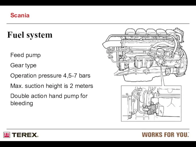
- 85. Fuel system Feed pump Gear type Operation pressure 4,5-7 bars Max. suction height is 2 meters
- 86. Water separating filter “pre-filter” - Drainage must be carried out when filling fuel. - The filter
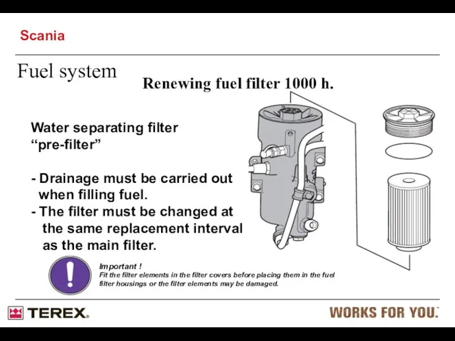
- 87. Renewing fuel filter 1000 h. Water separating filter “pre-filter” - Drainage must be carried out when
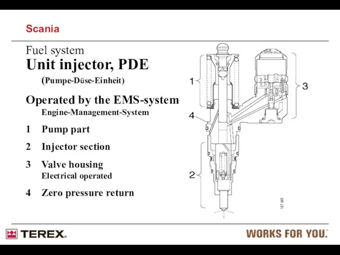
- 88. Fuel system Unit injector, PDE (Pumpe-Düse-Einheit) Operated by the EMS-system Engine-Management-System 1 Pump part 2 Injector
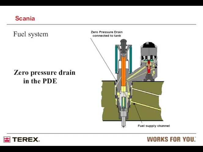
- 89. Fuel system Zero pressure drain in the PDE Scania
- 90. Pressure between: 4,5 – 7 Bar Pressure gauge Mechanical 98 113 Pressure gauge Electronically 99 362
- 91. Pressure between: 4,5 – 7 Bar Connect pressure gauge 99 362 to the bleeder nipple on
- 92. Trouble shooting the unit injector (PDE) Measure the resistance between the two poles on the solenoid
- 93. One of the unit injectors may be short circuited to earth via the chassis. This means
- 94. Dismantling the PDE 87 596 Scania
- 95. Dismantling the PDE WARNING! The fuel system must be empty before dismantling the unit injector otherwise
- 96. Mounting the PDE Engine oil should be used to lubricate O-rings when mounting Scania
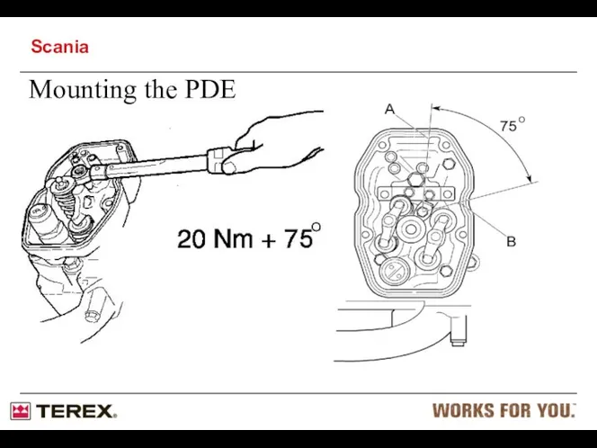
- 97. Mounting the PDE Scania
- 98. Mounting the PDE IMPORTANT! Make sure that the cable terminals are the right way round when
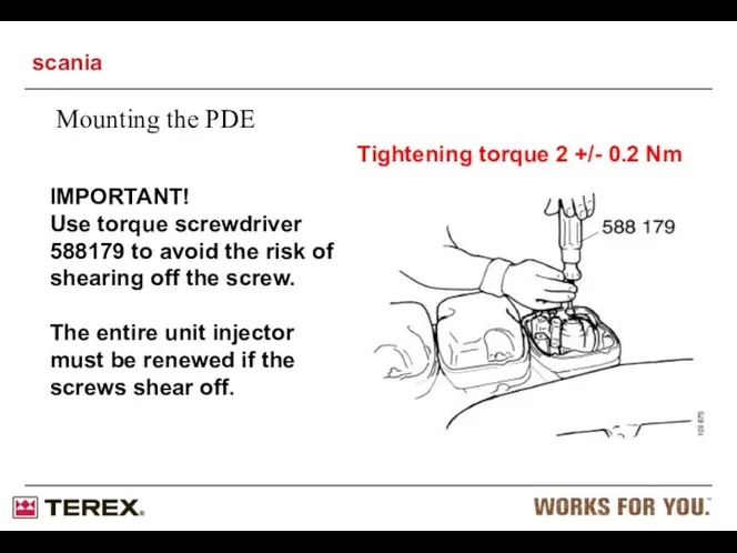
- 99. Mounting the PDE Tightening torque 2 +/- 0.2 Nm IMPORTANT! Use torque screwdriver 588179 to avoid
- 100. Tools for adjusting PDE 99 414 = PDE 31 99 442 = PDE 32 Scania
- 101. Tools for adjusting PDE Scania
- 102. Filling phase During the filling phase, pump plunger (2) moves up to it’s highest position. Fuel
- 103. Spill phase The spill phase begins when the camshaft starts to press pump plunger (2). The
- 104. Injection phase The injection phase begins when the fuel valve (1) closes. The fuel valve closes
- 105. Pressure reduction phase Injection stops when the fuel valve (1) opens and the pressure in the
- 106. Manufactured by Continental in Germany Designed to be mounted on the engine block with cooling Scania
- 107. CAN communication Scania
- 108. Electrical system, Designations Scania
- 109. Electrical system, EMS Scania
- 110. Black Grey Electrical system, EMS Scania
- 112. SDP3 Engine Diagnostic 15504817 15504818 15504875 Software: SDP3 Source: Terex, Part No: 15504815 Cost: £???? USB
- 113. Possible settings all speed: Customer adapted output curves Speed droop (Standard, (approx 10%) Stiff (approx 4%
- 114. There are also cables marked with two colours, e.g. YE/WH. The above table provides all possible
- 115. - Mainly used to detect faulty injectors. - Engine must run at no load and be
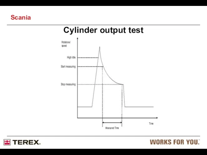
- 116. The engine revs up to a fixed (1800) RPM with a fixed fuel amount. - All
- 117. Cylinder output test Scania
- 118. Short time could indicate: - Bad injector. - Low compression - Seized piston Cylinder output test
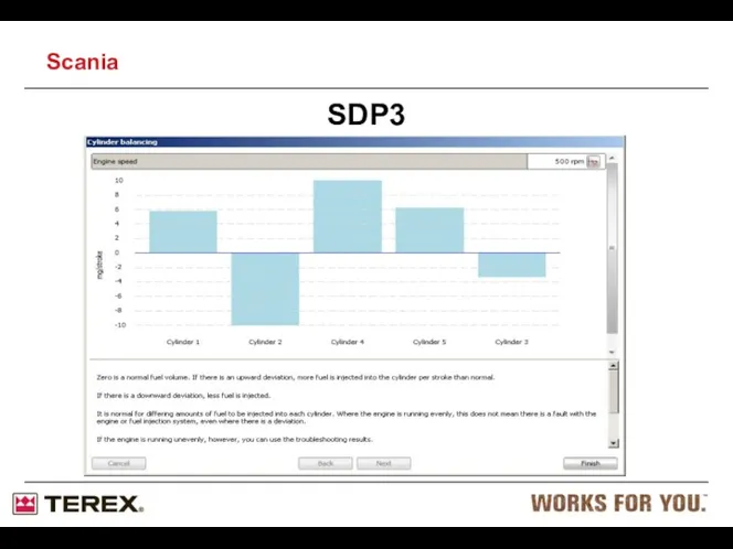
- 119. SDP3 Scania
- 120. Engine must run at no load and be internally synchronized. - Engine temperature should be >50
- 121. Compression test Scania
- 122. The result is speed. (look for the most prominent) - High speed could indicate low compression.
- 123. Fuel heater XPI Deutsch contact DTP04-2P Max 350W Thermostat with working range 5°C - 24°C Scania
- 124. Customer interface VCI EMS SCR/EGR C4001 EMS control unit C4000 Diagnostics C4002 SCR or EGR system
- 125. EMS contact C4001 4. Supply U30 3. Ignition U15 2. Ground U31 1. Supply U30 5.
- 127. Скачать презентацию
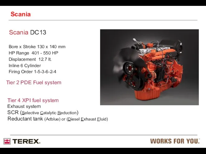
Bore x Stroke 130 x 140 mm
HP Range 401 - 550
HP Range 401 - 550
Type designation
Engine plate
The engine type designation indicates engine type, size and
Type designation
Engine plate
The engine type designation indicates engine type, size and
Location on engine
The illustrations show a normal version of a DC09
Location on engine
The illustrations show a normal version of a DC09
Location on engine
Scania
The illustrations show a normal version of a DC13
Location on engine
Scania
The illustrations show a normal version of a DC13
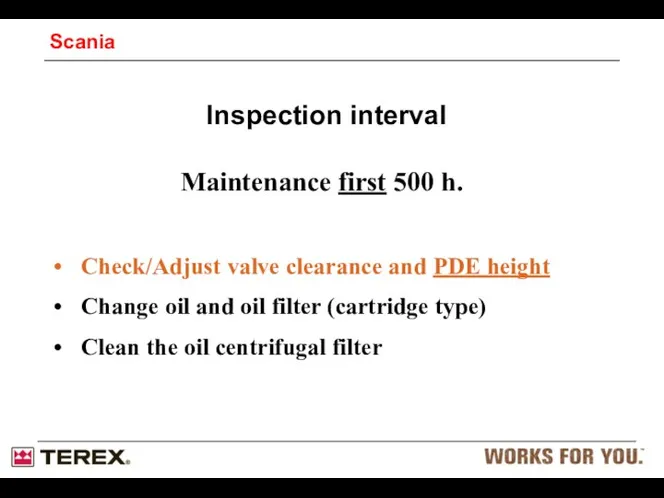
Maintenance first 500 h.
Check/Adjust valve clearance and PDE height
Change oil and
Maintenance first 500 h.
Check/Adjust valve clearance and PDE height
Change oil and
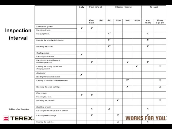
Inspection interval
1 =More often if required
Inspection interval
1 =More often if required
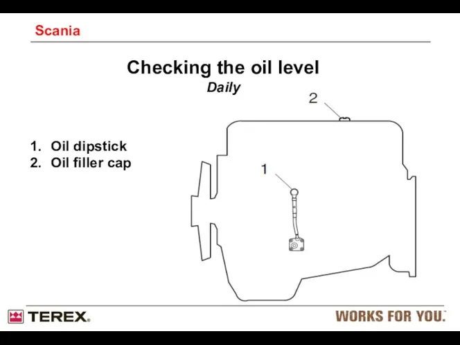
Checking the oil level
Daily
Oil dipstick
Oil filler cap
Scania
Checking the oil level
Daily
Oil dipstick
Oil filler cap
Scania
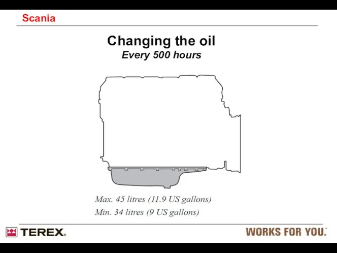
Changing the oil
Every 500 hours
Scania
Changing the oil
Every 500 hours
Scania
Low CO2 emissions
High outputs
Response
Sulphur level in fuel
Cooling demand
Prepared for Stage
Low CO2 emissions
High outputs
Response
Sulphur level in fuel
Cooling demand
Prepared for Stage
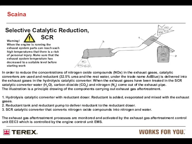
Selective Catalytic Reduction,
SCR
Warning!
When the engine is running the exhaust system
Selective Catalytic Reduction,
SCR
Warning!
When the engine is running the exhaust system

Selective Catalytic Reduction
SCR
Scania
Overview of the system.
The system contains a tank with
Selective Catalytic Reduction
SCR
Scania
Overview of the system.
The system contains a tank with
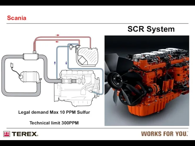
SCR System
Scania
Legal demand Max 10 PPM Sulfur
Technical limit 300PPM
SCR System
Scania
Legal demand Max 10 PPM Sulfur
Technical limit 300PPM
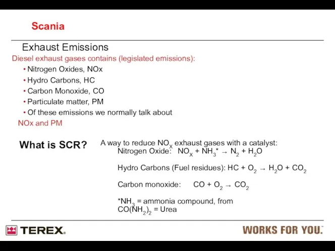
Exhaust Emissions
Diesel exhaust gases contains (legislated emissions):
Nitrogen Oxides, NOx
Hydro Carbons, HC
Carbon
Exhaust Emissions
Diesel exhaust gases contains (legislated emissions):
Nitrogen Oxides, NOx
Hydro Carbons, HC
Carbon
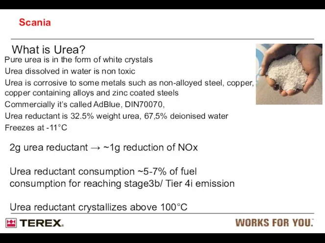
What is Urea?
Pure urea is in the form of white crystals
Urea
What is Urea?
Pure urea is in the form of white crystals
Urea
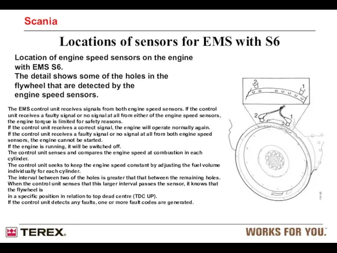
Location of engine speed sensors on the engine with EMS S6.
Location of engine speed sensors on the engine with EMS S6.
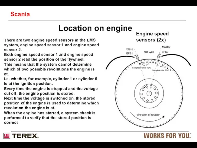
Engine speed sensors (2x)
Location on engine
There are two engine speed sensors
Engine speed sensors (2x)
Location on engine
There are two engine speed sensors
SCR Catalysts working temp
Exhaust temp > 200°C necessary
Good function above 250°C
Maximum
SCR Catalysts working temp
Exhaust temp > 200°C necessary
Good function above 250°C
Maximum
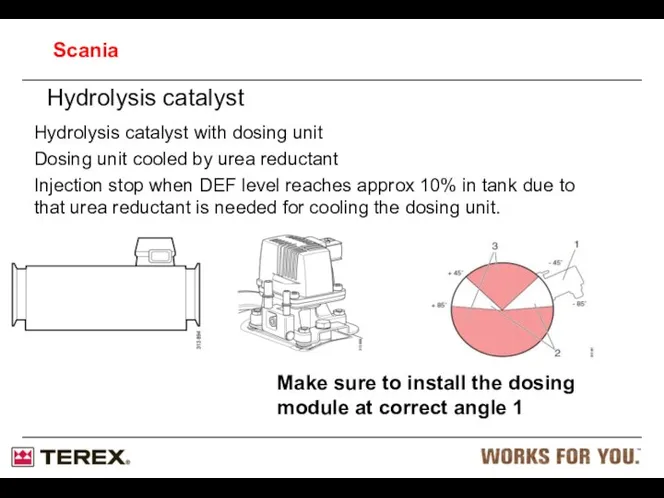
Hydrolysis catalyst
Hydrolysis catalyst with dosing unit
Dosing unit cooled by urea
Hydrolysis catalyst
Hydrolysis catalyst with dosing unit
Dosing unit cooled by urea
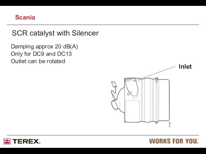
SCR catalyst with Silencer
Damping approx 20 dB(A)
Only for DC9 and DC13
Outlet
SCR catalyst with Silencer
Damping approx 20 dB(A)
Only for DC9 and DC13
Outlet
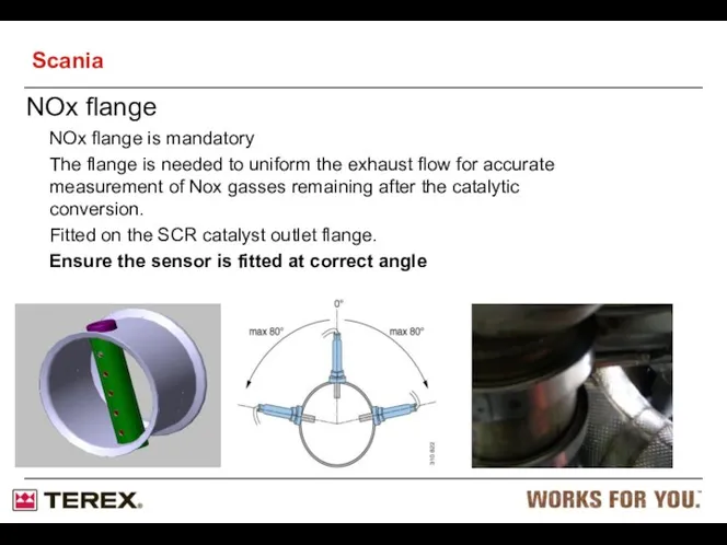
NOx flange
NOx flange is mandatory
The flange is needed to uniform the
NOx flange
NOx flange is mandatory
The flange is needed to uniform the
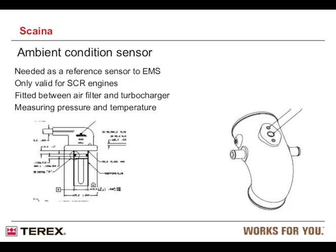
Ambient condition sensor
Needed as a reference sensor to EMS
Only valid for
Ambient condition sensor
Needed as a reference sensor to EMS
Only valid for
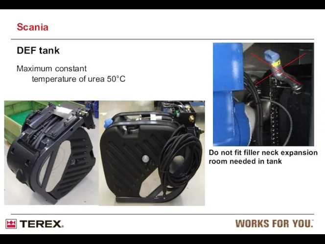
DEF tank
Scania
Maximum constant
temperature of urea 50°C
Do not fit filler neck
DEF tank
Scania
Maximum constant
temperature of urea 50°C
Do not fit filler neck

Red arrow water
Blue arrow urea
Filter
SCR tank module flow
SCR pick up
Red arrow water
Blue arrow urea
Filter
SCR tank module flow
SCR pick up
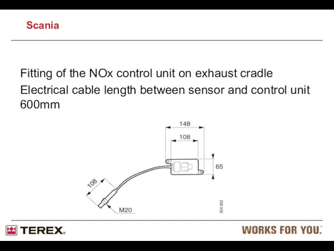
Fitting of the NOx control unit on exhaust cradle
Electrical cable length
Electrical cable length
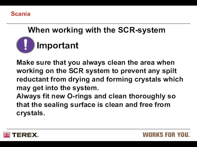
Important
Make sure that you always clean the area when working
Important
Make sure that you always clean the area when working
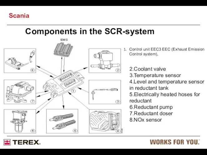
Components in the SCR-system
2.Coolant valve
3.Temperature sensor
4.Level and temperature sensor in
Components in the SCR-system
2.Coolant valve
3.Temperature sensor
4.Level and temperature sensor in
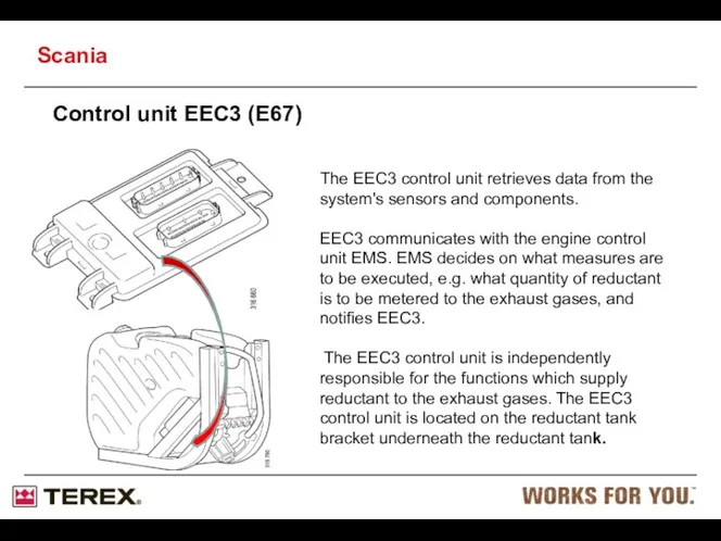
Control unit EEC3 (E67)
The EEC3 control unit retrieves data from the
Control unit EEC3 (E67)
The EEC3 control unit retrieves data from the
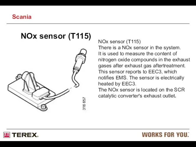
NOx sensor (T115)
NOx sensor (T115)
There is a NOx sensor in the
NOx sensor (T115)
NOx sensor (T115)
There is a NOx sensor in the
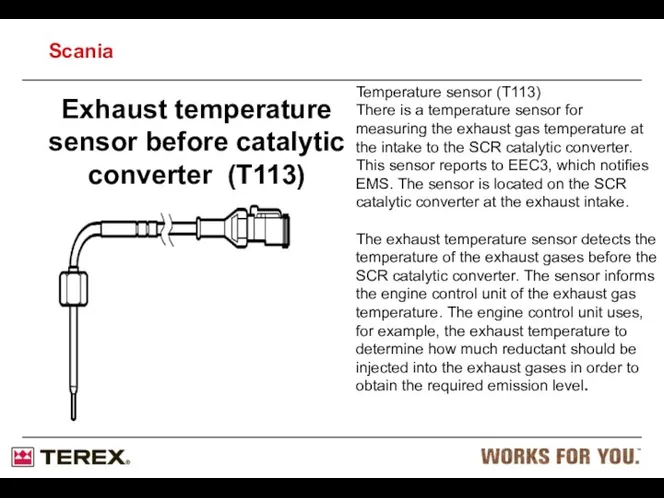
Exhaust temperature sensor before catalytic converter (T113)
Temperature sensor (T113)
There is a
Exhaust temperature sensor before catalytic converter (T113)
Temperature sensor (T113)
There is a
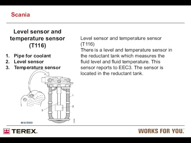
Level sensor and temperature sensor (T116)
Pipe for coolant
Level sensor
Temperature sensor
Level sensor
Level sensor and temperature sensor (T116)
Pipe for coolant
Level sensor
Temperature sensor
Level sensor

Reductant pump (V183)
Reductant pump (V183)
To achieve the right reductant pressure prior
Reductant pump (V183)
Reductant pump (V183)
To achieve the right reductant pressure prior
Reductant pump (V183)
To ensure that the correct quantity of reductant is
Reductant pump (V183)
To ensure that the correct quantity of reductant is

Reductant pump (V183)
Intake, reductant
Outlet, reductant
Prefilter, reductant
Antifreeze
Overflow valve
Port to pump chamber
Check valve
The
Reductant pump (V183)
Intake, reductant
Outlet, reductant
Prefilter, reductant
Antifreeze
Overflow valve
Port to pump chamber
Check valve
The

Reductant pump (V183)
Port from prefilter
Intake valve
Pump diaphragm
Outlet valve
Port to reductant filter
Port
Reductant pump (V183)
Port from prefilter
Intake valve
Pump diaphragm
Outlet valve
Port to reductant filter
Port
Reductant doser (V182)
Connection for electrical connector
Reductant inlet
Reductant outlet
Metering nozzle
Ventilation
There is an
Reductant doser (V182)
Connection for electrical connector
Reductant inlet
Reductant outlet
Metering nozzle
Ventilation
There is an
Reductant doser (V182)
Restriction
Prefilter
Pressure and temperature sensor
Metering nozzle
Solenoid valve
Heater element
.
Important!
Do not switch
Reductant doser (V182)
Restriction
Prefilter
Pressure and temperature sensor
Metering nozzle
Solenoid valve
Heater element
.
Important!
Do not switch
Reductant doser (V182)
Graphite gasket
Metering nozzle
A graphite gasket (1) is fitted
Reductant doser (V182)
Graphite gasket
Metering nozzle
A graphite gasket (1) is fitted
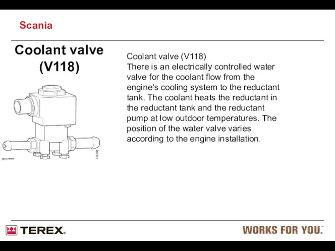
Coolant valve (V118)
Coolant valve (V118)
There is an electrically controlled water valve
Coolant valve (V118)
Coolant valve (V118)
There is an electrically controlled water valve
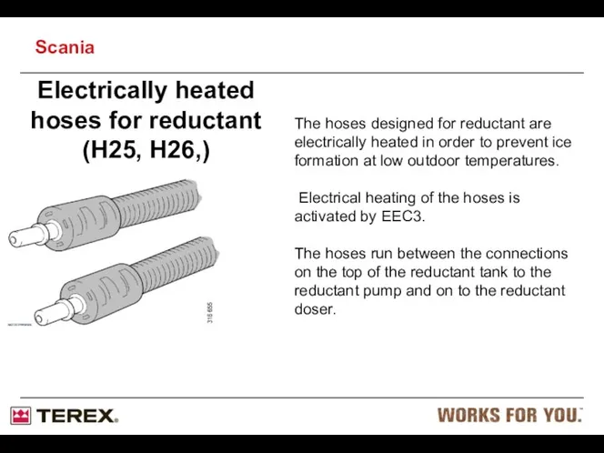
Electrically heated hoses for reductant
(H25, H26,)
The hoses designed for reductant
Electrically heated hoses for reductant
(H25, H26,)
The hoses designed for reductant
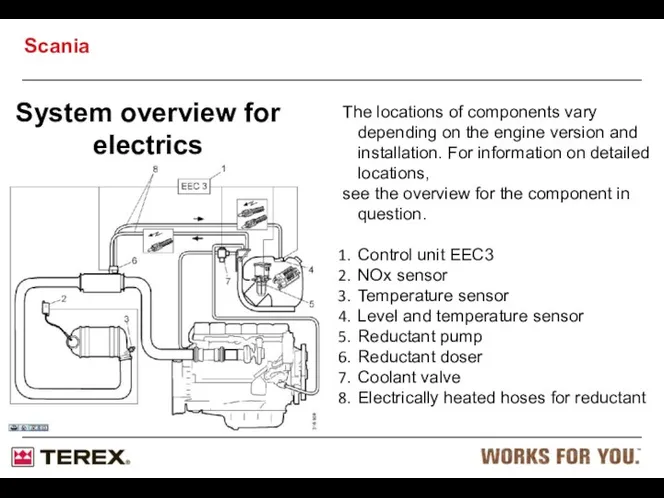
System overview for electrics
The locations of components vary depending on the
System overview for electrics
The locations of components vary depending on the
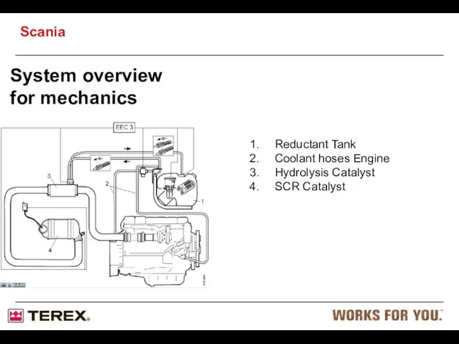
System overview for mechanics
Reductant Tank
Coolant hoses Engine
Hydrolysis Catalyst
SCR Catalyst
Scania
System overview for mechanics
Reductant Tank
Coolant hoses Engine
Hydrolysis Catalyst
SCR Catalyst
Scania

Reductant filter
Antifreeze
Reductant filter
The illustration shows the reductant filter (1) facing
Reductant filter
Antifreeze
Reductant filter
The illustration shows the reductant filter (1) facing
Exhaust gas aftertreatment function and working principle
Start
The reductant pump starts when
Exhaust gas aftertreatment function and working principle
Start
The reductant pump starts when
Operation and reductant metering
The exhaust gases are treated in a number
Operation and reductant metering
The exhaust gases are treated in a number
Shutdown
When the engine is switched off, the reductant pump continues for
Shutdown
When the engine is switched off, the reductant pump continues for
XPI = Extra high Pressure Injection
Scania XPI is a new generation
XPI = Extra high Pressure Injection
Scania XPI is a new generation
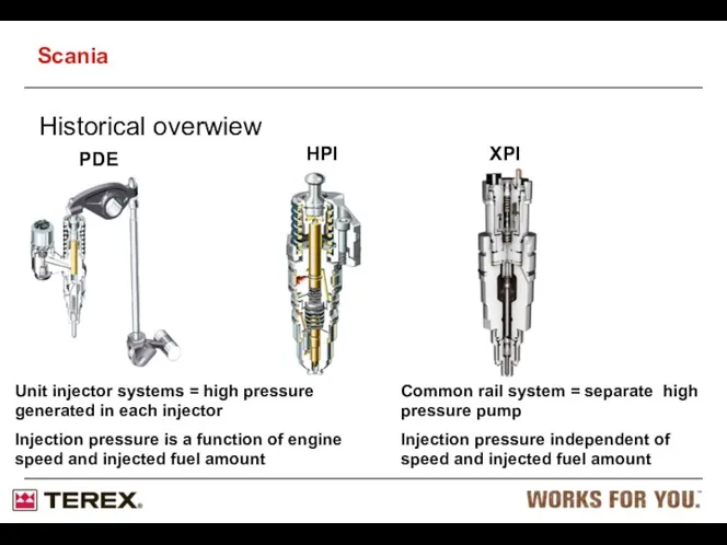
Historical overwiew
Unit injector systems = high pressure generated in each
Historical overwiew
Unit injector systems = high pressure generated in each
Benefits from Scania XPI
Injection timing or duration independent of camshaft position
Higher
Benefits from Scania XPI
Injection timing or duration independent of camshaft position
Higher
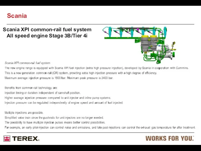
Scania XPI common-rail fuel system
All speed engine Stage 3B/Tier 4i
Scania
Scania XPI common-rail fuel system
All speed engine Stage 3B/Tier 4i
Scania
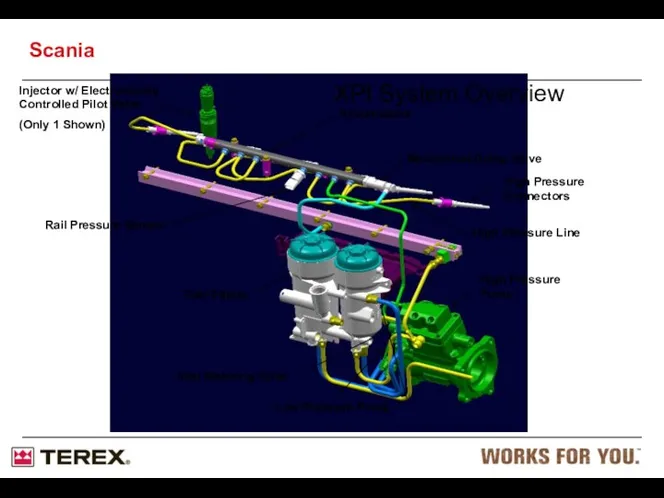
Injector w/ Electronically Controlled Pilot Valve
(Only 1 Shown)
Low Pressure Pump
High
Injector w/ Electronically Controlled Pilot Valve
(Only 1 Shown)
Low Pressure Pump
High
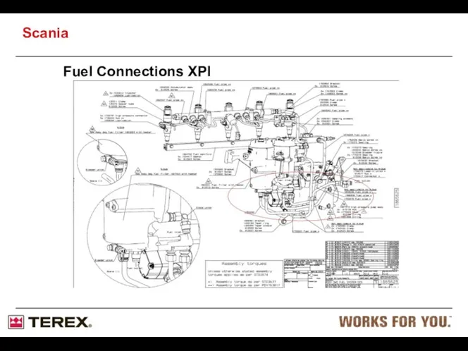
Fuel Connections XPI
Scania
Fuel Connections XPI
Scania
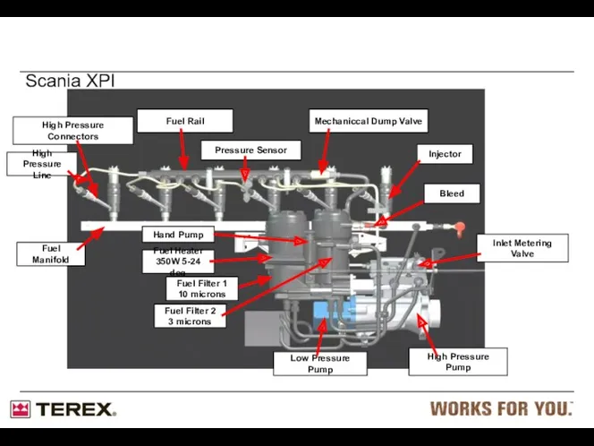
Scania XPI
High Pressure Connectors
Fuel Manifold
Fuel Heater
350W 5-24 deg
Hand Pump
Inlet Metering Valve
Low
Scania XPI
High Pressure Connectors
Fuel Manifold
Fuel Heater
350W 5-24 deg
Hand Pump
Inlet Metering Valve
Low
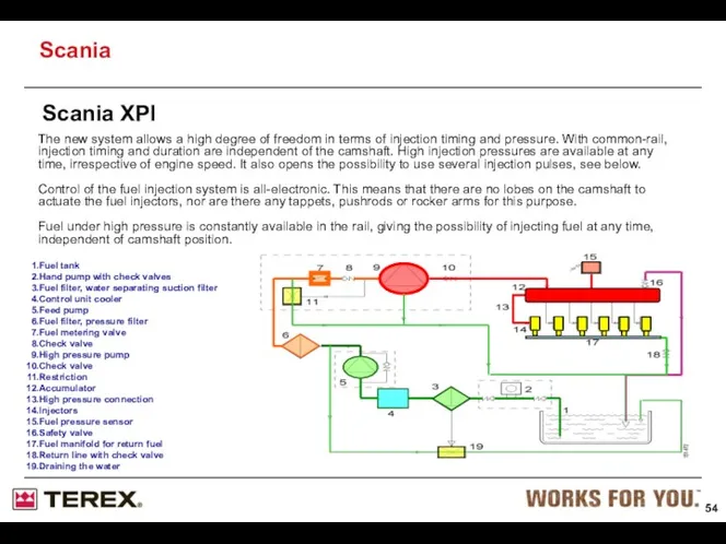
Fuel tank
Hand pump with check valves
Fuel filter, water separating
Hand pump with check valves
Fuel filter, water separating

Working principle of Scania XPI
Fuel is sucked from the tank by
Working principle of Scania XPI
Fuel is sucked from the tank by
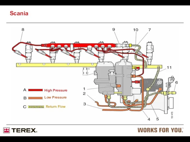
High Pressure
Low Pressure
Return Flow
Scania
High Pressure
Low Pressure
Return Flow
Scania

Venturi housing
Inlet from low pressure pump
Inlet from return manifold
Return to the
Venturi housing
Inlet from low pressure pump
Inlet from return manifold
Return to the

Mesh filter
The pressurized inlet to the Venturi housing is protected by
Mesh filter
The pressurized inlet to the Venturi housing is protected by
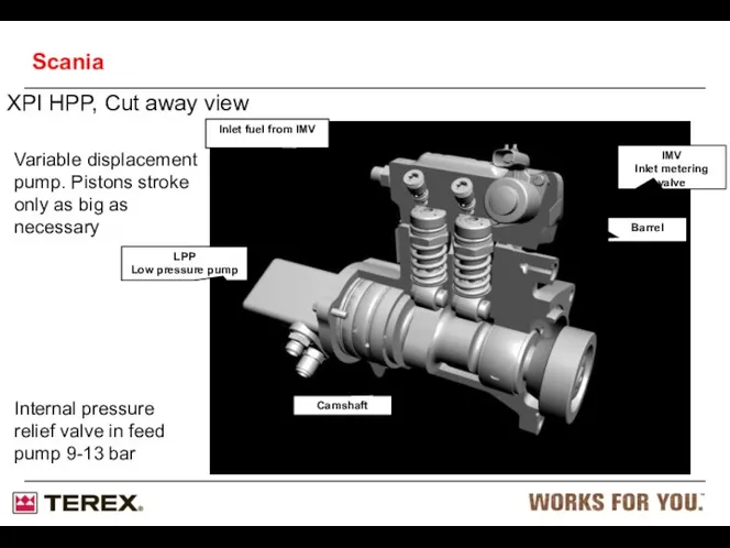
XPI HPP, Cut away view
IMV
Inlet metering valve
LPP
Low pressure pump
Camshaft
Inlet fuel from
XPI HPP, Cut away view
IMV
Inlet metering valve
LPP
Low pressure pump
Camshaft
Inlet fuel from

XPI HPP Head Assembly
Outlet checkvalve
Inlet checkvalve
Barrel
Seal washer
2-bump camshaft
Plunger lift roller
CeramicPlunger
Spring
Outlet
XPI HPP Head Assembly
Outlet checkvalve
Inlet checkvalve
Barrel
Seal washer
2-bump camshaft
Plunger lift roller
CeramicPlunger
Spring
Outlet
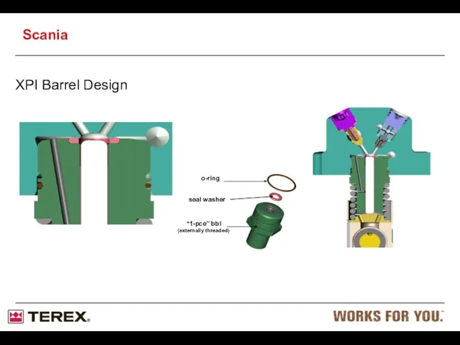
XPI Barrel Design
“1-pce” bbl (externally threaded)
seal washer
o-ring
Scania
XPI Barrel Design
“1-pce” bbl (externally threaded)
seal washer
o-ring
Scania
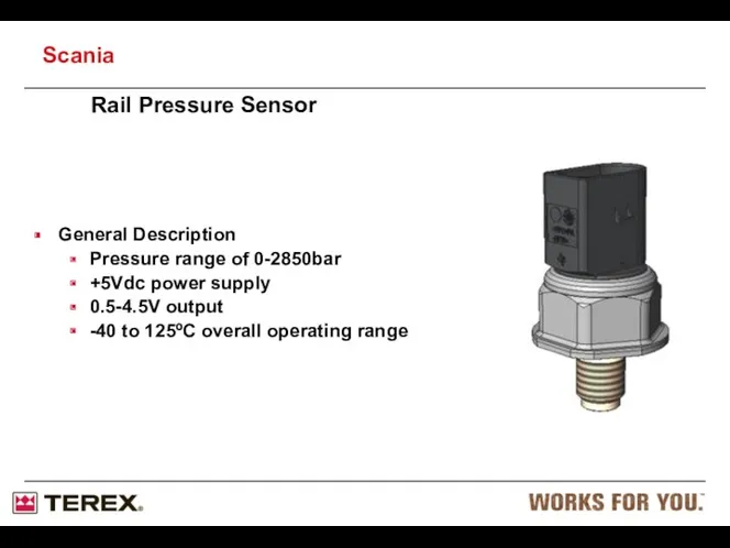
Rail Pressure Sensor
General Description
Pressure range of 0-2850bar
+5Vdc power supply
0.5-4.5V output
-40 to
Rail Pressure Sensor
General Description
Pressure range of 0-2850bar
+5Vdc power supply
0.5-4.5V output
-40 to
General Description
Pressure range of 0-2850bar
+5Vdc power supply
0.5-4.5V output
-40 to 125ºC overall
General Description
Pressure range of 0-2850bar
+5Vdc power supply
0.5-4.5V output
-40 to 125ºC overall
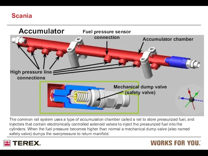
Accumulator
Accumulator chamber
High pressure line connections
Mechanical dump valve (safety valve)
Fuel pressure sensor
Accumulator
Accumulator chamber
High pressure line connections
Mechanical dump valve (safety valve)
Fuel pressure sensor
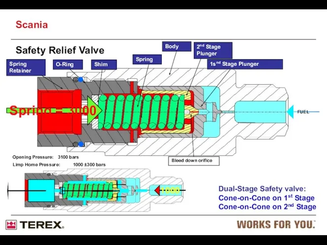
Dual-Stage Safety valve:
Cone-on-Cone on 1st Stage
Cone-on-Cone on 2nd Stage
Spring Retainer
O-Ring
Shim
Spring
Body
2nd Stage
Dual-Stage Safety valve:
Cone-on-Cone on 1st Stage
Cone-on-Cone on 2nd Stage
Spring Retainer
O-Ring
Shim
Spring
Body
2nd Stage

XPI Injector
Injector Scania XPI
Function
Phase 1, no power to the
XPI Injector
Injector Scania XPI
Function
Phase 1, no power to the
Phase 1 & 2 of Injection
Scania
Phase 1 & 2 of Injection
Scania
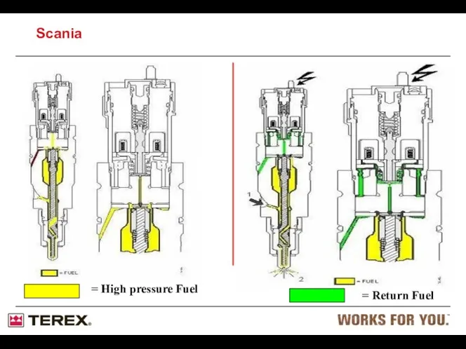
= High pressure Fuel
= Return Fuel
Scania
= High pressure Fuel
= Return Fuel
Scania

Injectors: Individual adjustment code
Each injector has an individual adjustment code. This
Injectors: Individual adjustment code
Each injector has an individual adjustment code. This
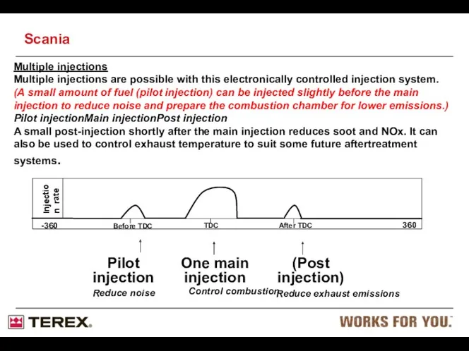
Multiple injections
Multiple injections are possible with this electronically controlled injection system.
Multiple injections
Multiple injections are possible with this electronically controlled injection system.

Injector assembly
High Pressure Connector
Injector clamp
High Pressure Line
Scania
Injector assembly
High Pressure Connector
Injector clamp
High Pressure Line
Scania

Cleanliness requirement
Many internal parts in the system are sensitive to
Cleanliness requirement
Many internal parts in the system are sensitive to
Cleanliness requirement: Pilot valve
Seat
Scania
Cleanliness requirement: Pilot valve
Seat
Scania
Cleanliness requirements: Pilot valve ball
The size of the ball is
Cleanliness requirements: Pilot valve ball
The size of the ball is

Cleanliness requirement: General
Do not use compressed air for cleaning purposes.
Use
Cleanliness requirement: General
Do not use compressed air for cleaning purposes.
Use
Service: Safety
Due to the high fuel pressure, leakage can cause jets
Service: Safety
Due to the high fuel pressure, leakage can cause jets
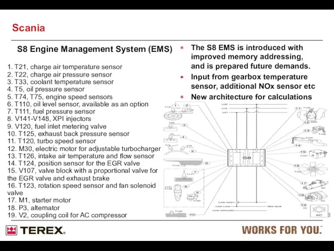
S8 Engine Management System (EMS)
The S8 EMS is introduced with improved
S8 Engine Management System (EMS)
The S8 EMS is introduced with improved
Troubleshooting: Tools
To apply the methods described here you need the pressure
Troubleshooting: Tools
To apply the methods described here you need the pressure
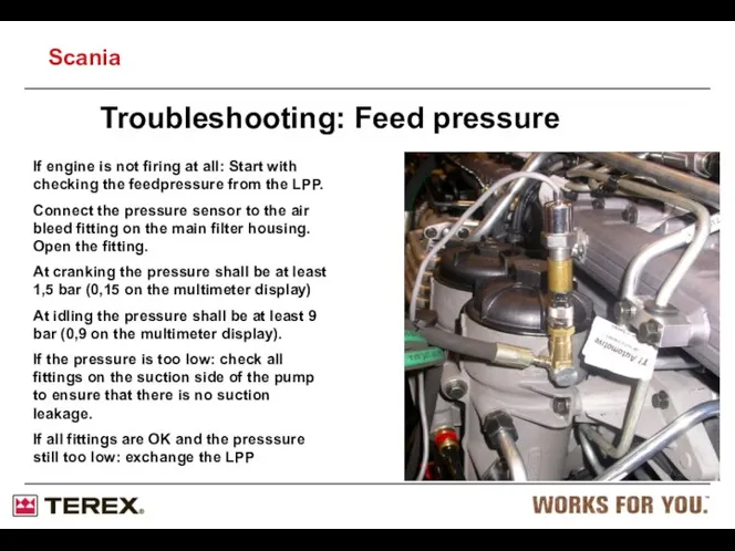
If engine is not firing at all: Start with checking the
If engine is not firing at all: Start with checking the
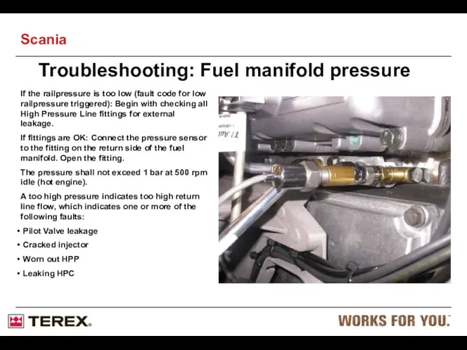
If the railpressure is too low (fault code for low railpressure
If the railpressure is too low (fault code for low railpressure
Fuel system, PDE
(Pumpe-Düse-Einheit)
Scania
Fuel system, PDE
(Pumpe-Düse-Einheit)
Scania
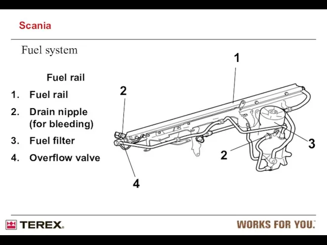
Fuel system
Fuel rail
Fuel rail
Drain nipple
(for bleeding)
Fuel filter
Overflow valve
3
4
1
2
2
Scania
Fuel system
Fuel rail
Fuel rail
Drain nipple
(for bleeding)
Fuel filter
Overflow valve
3
4
1
2
2
Scania
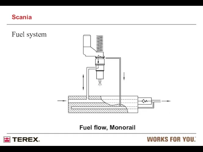
Fuel system
Fuel flow, Monorail
Scania
Fuel system
Fuel flow, Monorail
Scania
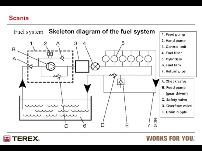
Fuel system
Skeleton diagram of the fuel system
1. Feed pump
2. Hand
Fuel system
Skeleton diagram of the fuel system
1. Feed pump
2. Hand
Fuel system
Feed pump
Gear type
Operation pressure 4,5-7 bars
Max. suction height is 2
Fuel system
Feed pump
Gear type
Operation pressure 4,5-7 bars
Max. suction height is 2
Water separating filter
“pre-filter”
- Drainage must be carried out
when filling fuel.
-
Water separating filter
“pre-filter”
- Drainage must be carried out
when filling fuel.
-
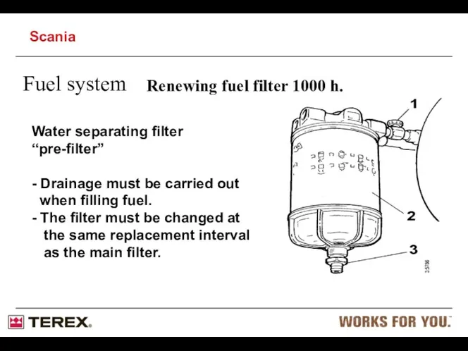
Renewing fuel filter 1000 h.
Water separating filter
“pre-filter”
- Drainage must be carried
Renewing fuel filter 1000 h.
Water separating filter
“pre-filter”
- Drainage must be carried
Fuel system
Unit injector, PDE
(Pumpe-Düse-Einheit)
Operated by the EMS-system
Engine-Management-System
1 Pump part
2 Injector section
Valve housing
Electrical
Fuel system
Unit injector, PDE
(Pumpe-Düse-Einheit)
Operated by the EMS-system
Engine-Management-System
1 Pump part
2 Injector section
Valve housing
Electrical
Fuel system
Zero pressure drain
in the PDE
Scania
Fuel system
Zero pressure drain
in the PDE
Scania
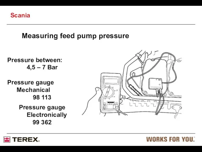
Pressure between:
4,5 – 7 Bar
Pressure gauge Mechanical
98 113
Pressure gauge Electronically
99 362
Pressure between:
4,5 – 7 Bar
Pressure gauge Mechanical
98 113
Pressure gauge Electronically
99 362

Pressure between:
4,5 – 7 Bar
Connect pressure gauge 99 362 to the
Connect pressure gauge 99 362 to the
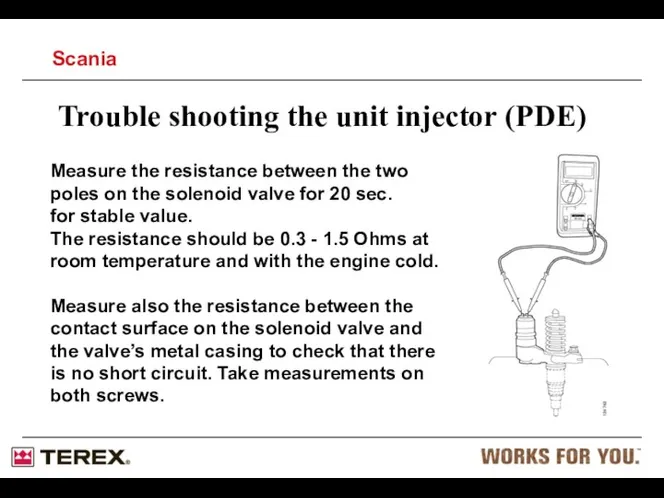
Trouble shooting the unit injector (PDE)
Measure the resistance between the two
Trouble shooting the unit injector (PDE)
Measure the resistance between the two
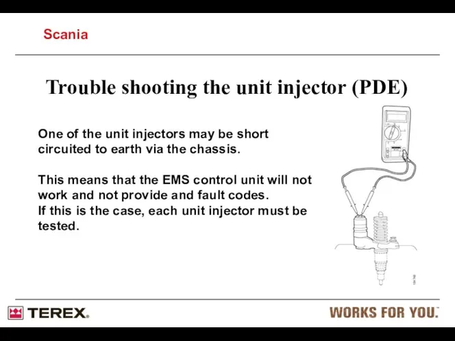
One of the unit injectors may be short circuited to earth
One of the unit injectors may be short circuited to earth
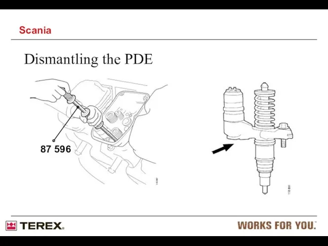
Dismantling the PDE
87 596
Scania
Dismantling the PDE
87 596
Scania
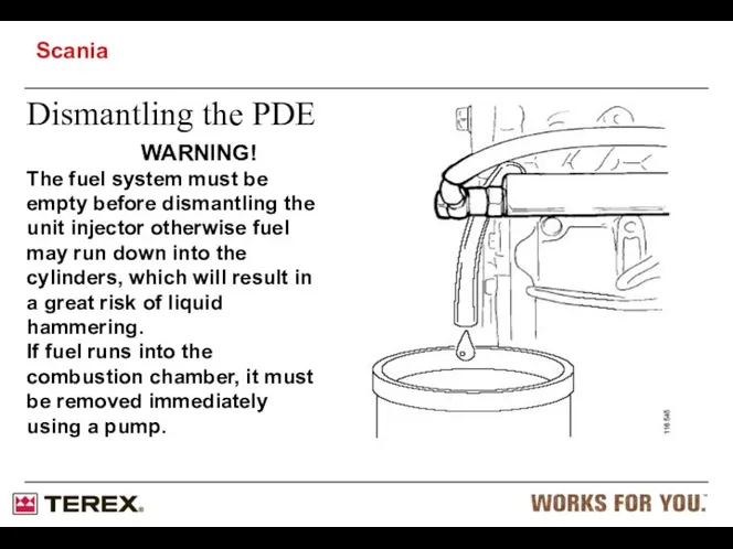
Dismantling the PDE
WARNING!
The fuel system must be
empty before dismantling the
unit injector
Dismantling the PDE
WARNING!
The fuel system must be
empty before dismantling the
unit injector
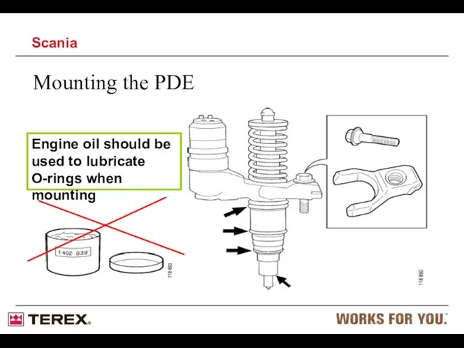
Mounting the PDE
Engine oil should be used to lubricate O-rings when
Mounting the PDE
Engine oil should be used to lubricate O-rings when
Mounting the PDE
Scania
Mounting the PDE
Scania
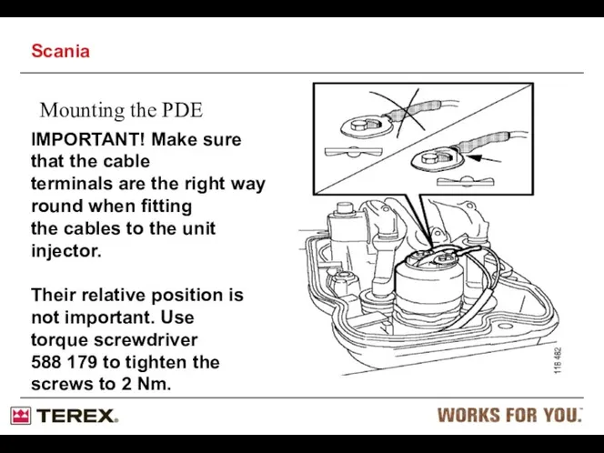
Mounting the PDE
IMPORTANT! Make sure that the cable
terminals are the right
Mounting the PDE
IMPORTANT! Make sure that the cable
terminals are the right
Mounting the PDE
Tightening torque 2 +/- 0.2 Nm
IMPORTANT!
Use torque screwdriver
Mounting the PDE
Tightening torque 2 +/- 0.2 Nm
IMPORTANT! Use torque screwdriver
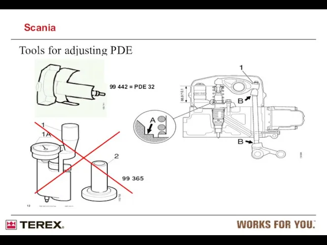
Tools for adjusting PDE
99 414 = PDE 31
99 442 = PDE
Tools for adjusting PDE
99 414 = PDE 31 99 442 = PDE
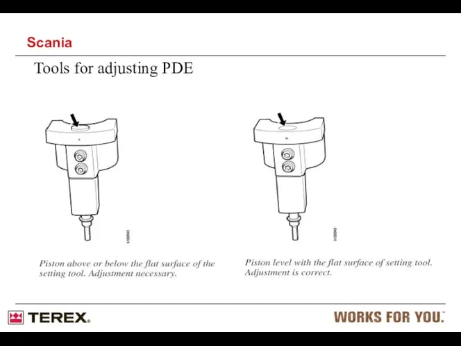
Tools for adjusting PDE
Scania
Tools for adjusting PDE
Scania
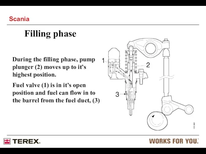
Filling phase
During the filling phase, pump plunger (2) moves up to
Filling phase
During the filling phase, pump plunger (2) moves up to
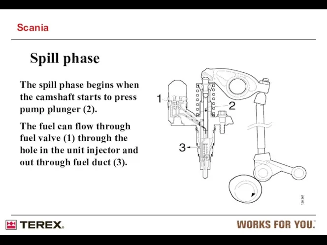
Spill phase
The spill phase begins when the camshaft starts to press
Spill phase
The spill phase begins when the camshaft starts to press
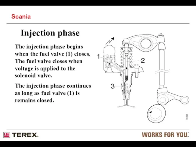
Injection phase
The injection phase begins when the fuel valve (1) closes.
Injection phase
The injection phase begins when the fuel valve (1) closes.
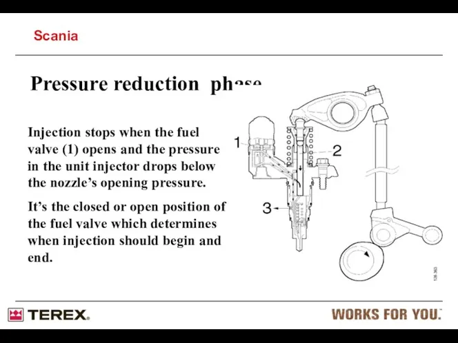
Pressure reduction phase
Injection stops when the fuel valve (1) opens and
Pressure reduction phase
Injection stops when the fuel valve (1) opens and
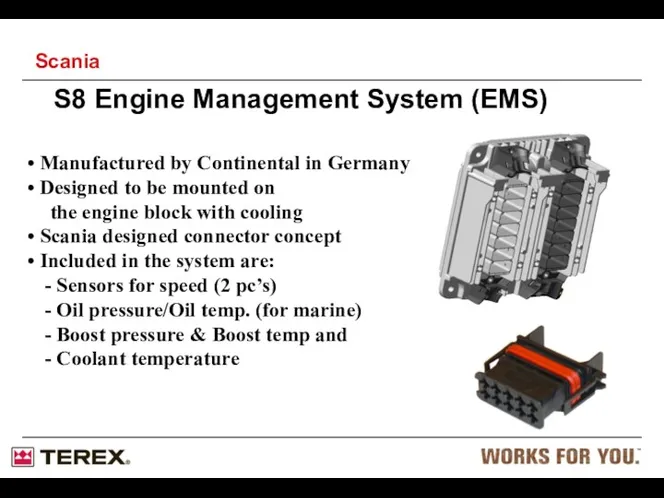
Manufactured by Continental in Germany
Designed to be mounted on
Manufactured by Continental in Germany
Designed to be mounted on
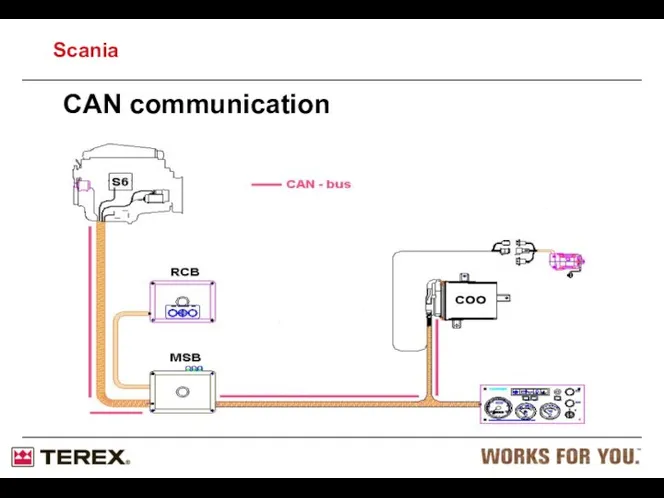
CAN communication
Scania
CAN communication
Scania
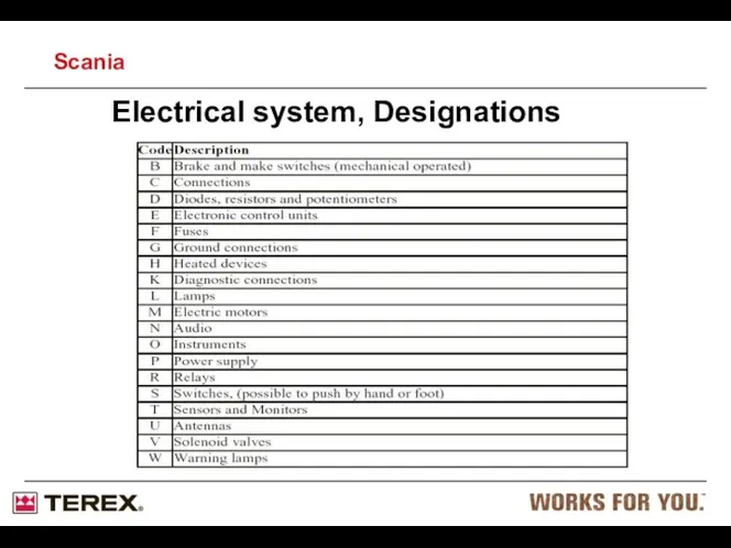
Electrical system, Designations
Scania
Electrical system, Designations
Scania
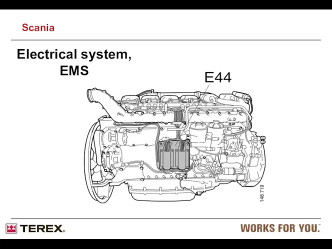
Electrical system, EMS
Scania
Electrical system, EMS
Scania
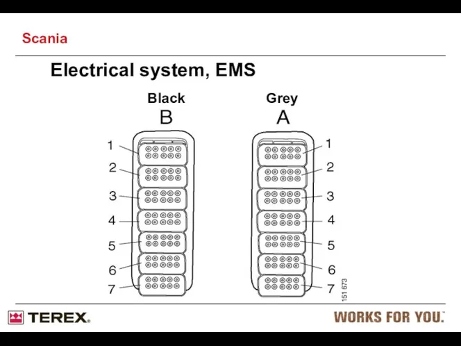
Black
Grey
Electrical system, EMS
Scania
Black
Grey
Electrical system, EMS
Scania

SDP3 Engine Diagnostic
15504817
15504818
15504875
Software: SDP3
Source: Terex, Part No: 15504815
Cost: £????
USB Key: 15504816
SDP3 Engine Diagnostic
15504817
15504818
15504875
Software: SDP3
Source: Terex, Part No: 15504815
Cost: £????
USB Key: 15504816
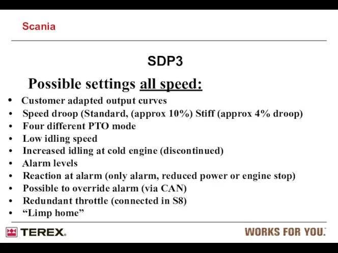
Possible settings all speed:
Customer adapted output curves
Speed droop (Standard,
Possible settings all speed:
Customer adapted output curves
Speed droop (Standard,
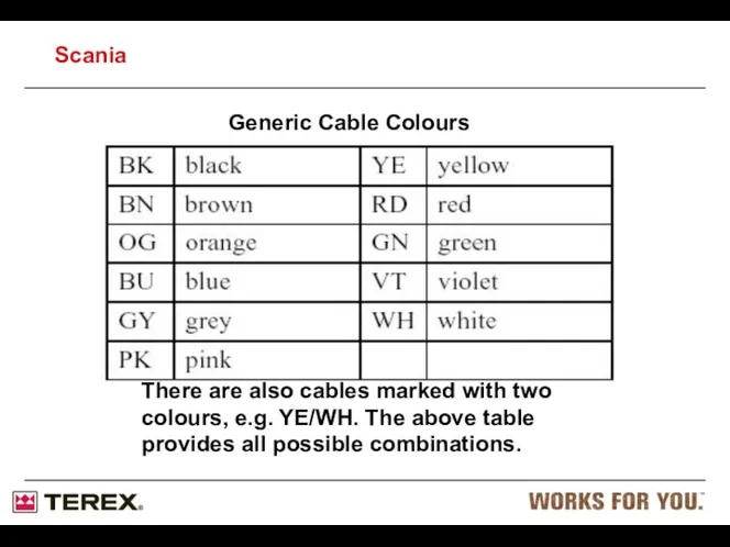
There are also cables marked with two colours, e.g. YE/WH. The
There are also cables marked with two colours, e.g. YE/WH. The
- Mainly used to detect faulty injectors.
- Engine must
- Mainly used to detect faulty injectors.
- Engine must
The engine revs up to a fixed (1800) RPM with a
The engine revs up to a fixed (1800) RPM with a
Cylinder output test
Scania
Cylinder output test
Scania
Short time could indicate:
- Bad injector.
- Low compression
Short time could indicate:
- Bad injector.
- Low compression
SDP3
Scania
SDP3
Scania
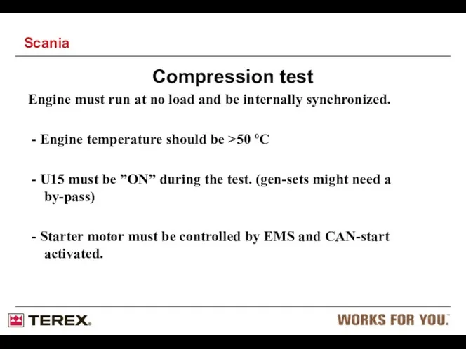
Engine must run at no load and be internally synchronized.
-
-

Compression test
Scania
Compression test
Scania

The result is speed. (look for the most prominent)
- High
The result is speed. (look for the most prominent)
- High
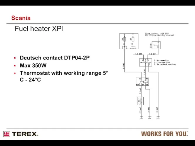
Fuel heater XPI
Deutsch contact DTP04-2P
Max 350W
Thermostat with working range 5°C -
Fuel heater XPI
Deutsch contact DTP04-2P
Max 350W
Thermostat with working range 5°C -
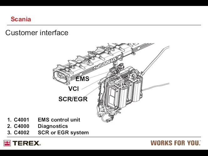
Customer interface
VCI
EMS
SCR/EGR
C4001 EMS control unit
C4000 Diagnostics
C4002 SCR or EGR system
Scania
Customer interface
VCI
EMS
SCR/EGR
C4001 EMS control unit
C4000 Diagnostics
C4002 SCR or EGR system
Scania
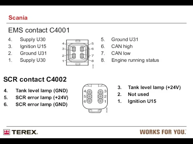
EMS contact C4001
4. Supply U30
3. Ignition U15
2. Ground U31
1. Supply U30
5. Ground U31
6. CAN high
7. CAN low
8. Engine
EMS contact C4001
4. Supply U30
3. Ignition U15
2. Ground U31
1. Supply U30
5. Ground U31
6. CAN high
7. CAN low
8. Engine
 Аэродинамика и летно-технические данные вертолёта. Тема №1. Основные понятия о несущей поверхности. Лекция №2
 Нормативные документы. Защита от шума. Проектирование звукоизоляции ограждающих конструкций жилых и общественных зданий
 Базовые механизмы каракури. Основные элементы малой механизации
 Модель урока по теме Тела и их взаимодействие. Инерциальное движение.
 Протипожежна та аварійно-рятувальна техніка. Улаштування і технічне обслуговування агрегатів силової передачі (9)
 Разработка урока Закон сохранения импульса
 Презентация к уроку: Физика и дорожная безопасность
 Обучение физике на основе индивидуального и дифференцированного подхода
 Воздух и атмосфера
 Замена электродвигателей СТД 8000 на электродвигатели марки Нидек на ЛПДС Чепурского АК Транснефть
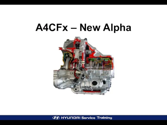 A4CFx – New Alpha. Power Train Variation Engine
 Өлшеу қателіктері
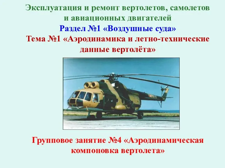 Аэродинамика и летно-технические данные вертолёта. Тема №1. Аэродинамическая компоновка вертолета. Групповое занятие №4
 Устройство автомобиля – шасси. Подвеска автомобиля
 Электромагнитное поле
 Понятие о технической системе. 6 класс
 Диффузия
 Конструкция двигателя и рабочие процессы
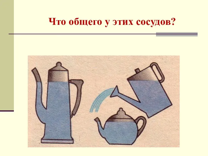 Что общего у этих сосудов?
 Презентация Испарение и конденсация
 Равномерное прямолинейное движение
 Законы аэродинамики
 Глава 3. Работа и энергия. Тема §1. Энергия, работа, мощность
 Плавание тел (фгос)
 Установочная лекция для студентов 1го курса. ИБФО (ускоренная форма обучения)
 Связь физики с различными сферами жизни
 Прямолинейное равномерное и равнопеременное движение. Тест
 Статические характеристики средств измерений. (Лекция 2)