- MDPS (TRW) Application Model

Содержание
- 2. Application Applied in both LHD and RHD as a standard including North American market. TRW GEN2
- 3. System structure Introduction Steering Column U/Joint MDPS SYSTEM MOBIS Power Head MOBIS LWR MT’G BRKT COCKPIT
- 4. Power head Components Worm Wheel O-Ring Bearing PCB Disk Light Guide Dust Cover Bearing Circle Lip
- 5. Power head Components Main Housing Anti-Rattle Spring Worm Wheel Sensor Ass’y ECU Motor Worm Shaft Assy
- 6. Control logic System Control + ▶ Main input signals for the control logic ① Steering Wheel
- 7. Torque sensor principle System Control Angle & torque sensor Gear Box Motor Rack & Pinion Gear
- 8. ASP (Absolute Steering Position) calibration System Control When ? MDPS Assmbly was replaced with new one
- 9. ASP (Absolute Steering Position) calibration System Control How? Ignition key ON (engine off) and set the
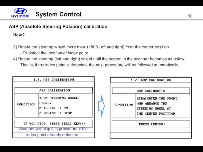
- 10. ASP (Absolute Steering Position) calibration System Control How? 3) Rotate the steering wheel more than ±180°(Left
- 11. ASP (Absolute Steering Position) calibration System Control How? 5) Set the front tire and steering wheel
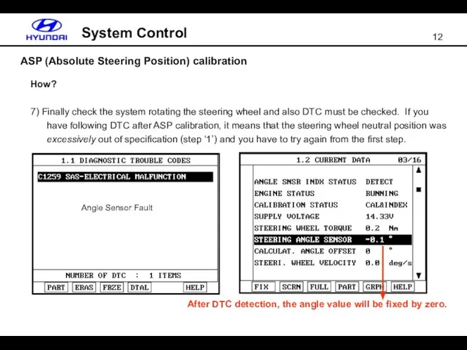
- 12. ASP (Absolute Steering Position) calibration System Control How? 7) Finally check the system rotating the steering
- 13. ASP (Absolute Steering Position) calibration System Control What happen if it is not done? In case
- 14. Input & Output System Control
- 15. Power supply & Relay System Control Motor relay (built in motor) ECM relay (built in ECM)
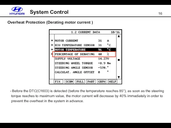
- 16. Overheat Protection (Derating motor current ) System Control Before the DTC(C1603) is detected (before the temperature
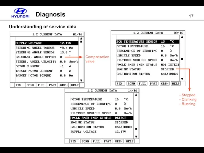
- 17. Understanding of service data Diagnosis Compensation value - Stopped - Cranking - Running
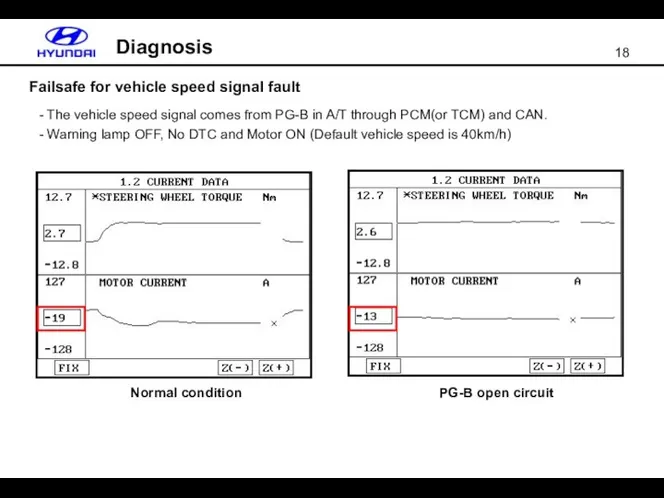
- 18. Failsafe for vehicle speed signal fault Diagnosis The vehicle speed signal comes from PG-B in A/T
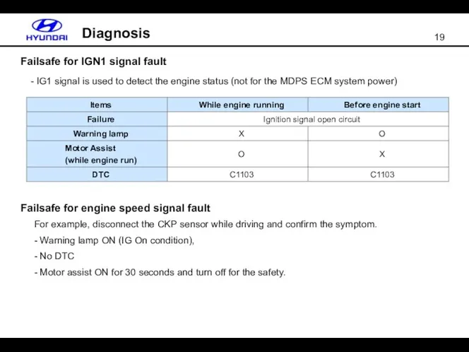
- 19. Failsafe for IGN1 signal fault Diagnosis - IG1 signal is used to detect the engine status
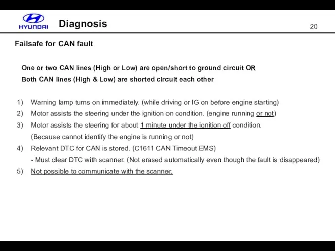
- 20. Failsafe for CAN fault Diagnosis One or two CAN lines (High or Low) are open/short to
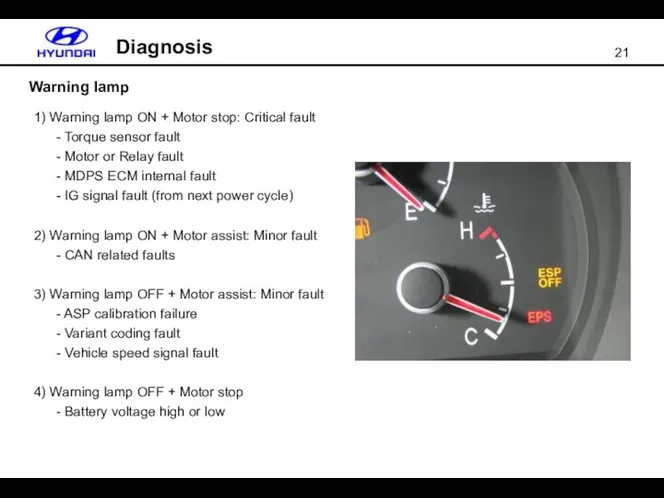
- 21. Warning lamp Diagnosis 1) Warning lamp ON + Motor stop: Critical fault - Torque sensor fault
- 23. Скачать презентацию
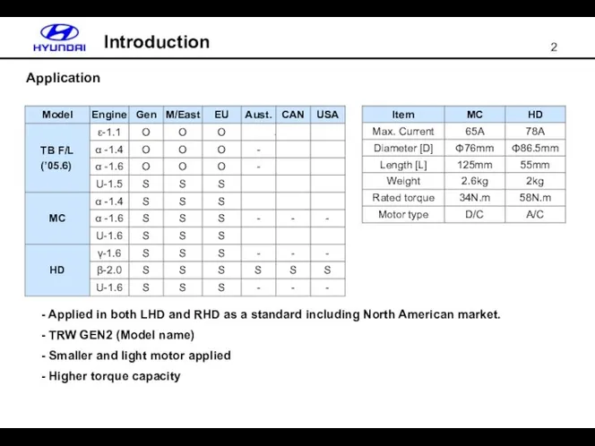
Application
Applied in both LHD and RHD as a standard including
Application
Applied in both LHD and RHD as a standard including
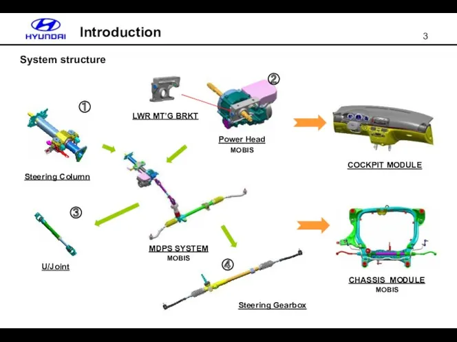
System structure
Introduction
Steering Column
U/Joint
MDPS SYSTEM
MOBIS
Power Head
MOBIS
LWR MT’G BRKT
COCKPIT MODULE
CHASSIS MODULE
MOBIS
①
②
③
④
System structure
Introduction
Steering Column
U/Joint
MDPS SYSTEM
MOBIS
Power Head
MOBIS
LWR MT’G BRKT
COCKPIT MODULE
CHASSIS MODULE
MOBIS
①
②
③
④
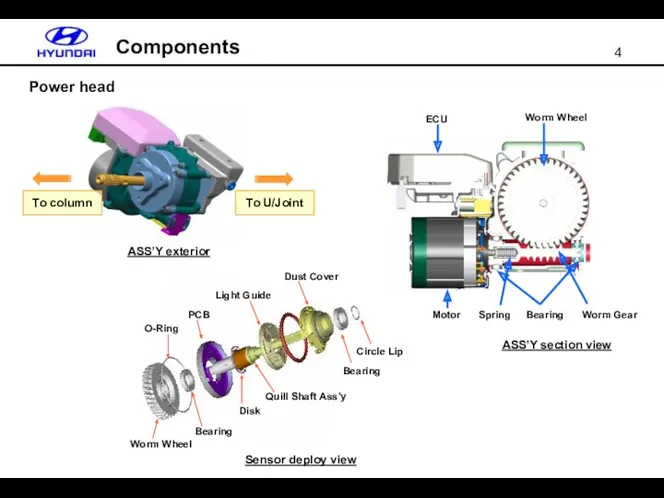
Power head
Components
Worm Wheel
O-Ring
Bearing
PCB
Disk
Light Guide
Dust Cover
Bearing
Circle Lip
Quill Shaft Ass’y
Sensor deploy view
ASS’Y section
Power head
Components
Worm Wheel
O-Ring
Bearing
PCB
Disk
Light Guide
Dust Cover
Bearing
Circle Lip
Quill Shaft Ass’y
Sensor deploy view
ASS’Y section
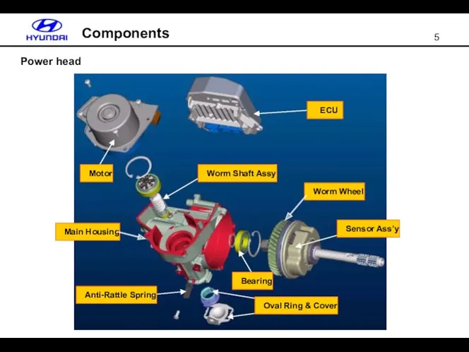
Power head
Components
Main Housing
Anti-Rattle Spring
Worm Wheel
Sensor Ass’y
ECU
Motor
Worm Shaft Assy
Bearing
Oval Ring & Cover
Power head
Components
Main Housing
Anti-Rattle Spring
Worm Wheel
Sensor Ass’y
ECU
Motor
Worm Shaft Assy
Bearing
Oval Ring & Cover
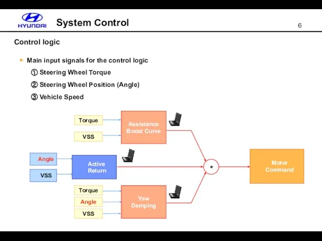
Control logic
System Control
+
▶ Main input signals for the control logic
①
Control logic
System Control
+
▶ Main input signals for the control logic
①
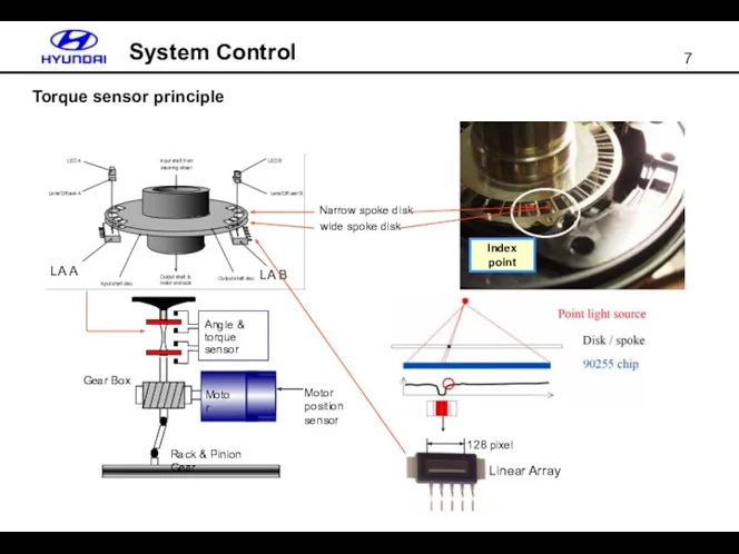
Torque sensor principle
System Control
Angle & torque sensor
Gear Box
Motor
Rack & Pinion Gear
LA
Torque sensor principle
System Control
Angle & torque sensor
Gear Box
Motor
Rack & Pinion Gear
LA
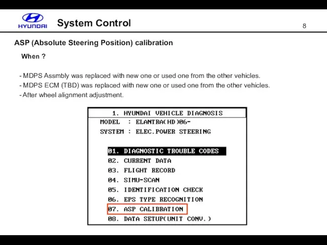
ASP (Absolute Steering Position) calibration
System Control
When ?
MDPS Assmbly was replaced
ASP (Absolute Steering Position) calibration
System Control
When ?
MDPS Assmbly was replaced
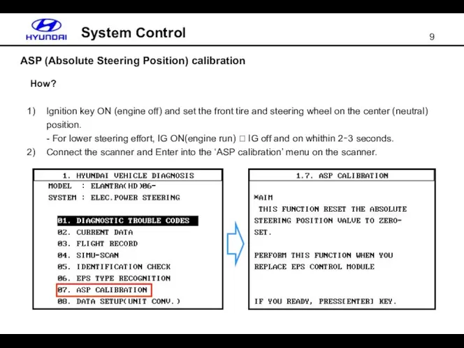
ASP (Absolute Steering Position) calibration
System Control
How?
Ignition key ON (engine off) and
ASP (Absolute Steering Position) calibration
System Control
How?
Ignition key ON (engine off) and
ASP (Absolute Steering Position) calibration
System Control
How?
3) Rotate the steering wheel more
ASP (Absolute Steering Position) calibration
System Control
How?
3) Rotate the steering wheel more

ASP (Absolute Steering Position) calibration
System Control
How?
5) Set the front tire and
ASP (Absolute Steering Position) calibration
System Control
How?
5) Set the front tire and
ASP (Absolute Steering Position) calibration
System Control
How?
7) Finally check the system rotating
ASP (Absolute Steering Position) calibration
System Control
How?
7) Finally check the system rotating
ASP (Absolute Steering Position) calibration
System Control
What happen if it is not
ASP (Absolute Steering Position) calibration
System Control
What happen if it is not
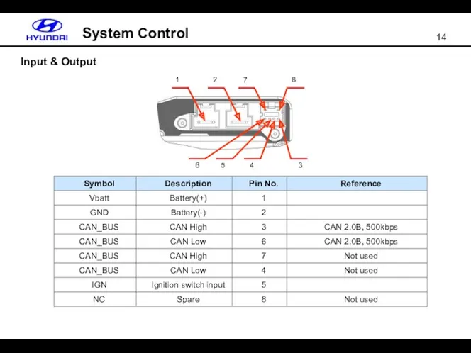
Input & Output
System Control
Input & Output
System Control
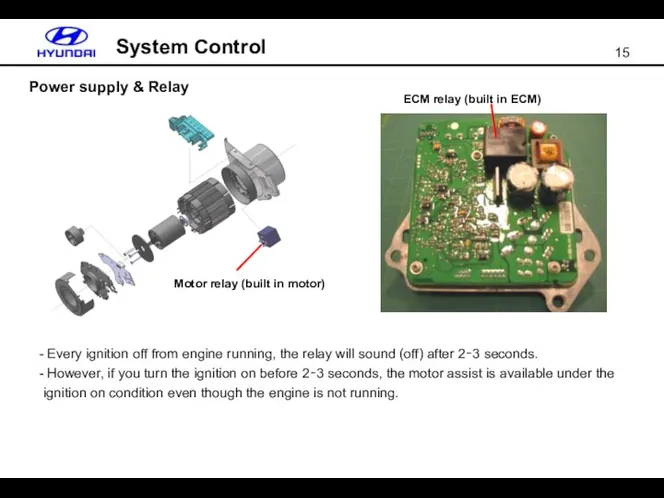
Power supply & Relay
System Control
Motor relay (built in motor)
ECM relay (built
Power supply & Relay
System Control
Motor relay (built in motor)
ECM relay (built
Overheat Protection (Derating motor current )
System Control
Before the DTC(C1603) is
Overheat Protection (Derating motor current )
System Control
Before the DTC(C1603) is
Understanding of service data
Diagnosis
Compensation value
- Stopped
- Cranking
- Running
Understanding of service data
Diagnosis
Compensation value
- Stopped
- Cranking
- Running
Failsafe for vehicle speed signal fault
Diagnosis
The vehicle speed signal comes
Failsafe for vehicle speed signal fault
Diagnosis
The vehicle speed signal comes
Failsafe for IGN1 signal fault
Diagnosis
- IG1 signal is used to detect
Failsafe for IGN1 signal fault
Diagnosis
- IG1 signal is used to detect
Failsafe for CAN fault
Diagnosis
One or two CAN lines (High or
Failsafe for CAN fault
Diagnosis
One or two CAN lines (High or
Warning lamp
Diagnosis
1) Warning lamp ON + Motor stop: Critical fault
-
Warning lamp
Diagnosis
1) Warning lamp ON + Motor stop: Critical fault
-
 Делимость электрического заряда. Электрон. Строение атома
 Характеристики электрического тока
 Формы управления системой ТОиР
 виды излучений. физика 11 класс
 Звуковые волны. 9 класс
 Hydraulic System
 Радиоволны
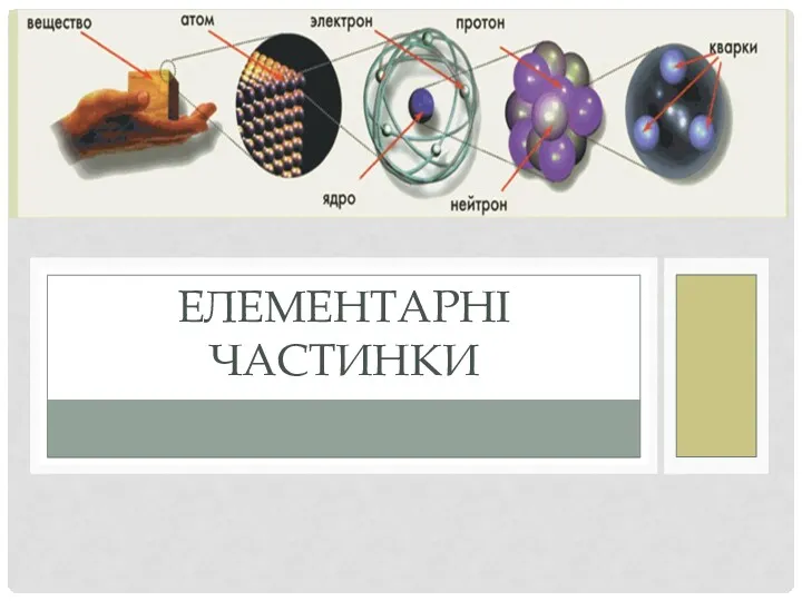 Елементарні частинки
 Drivetrain System
 Динамика вращательного движения
 Реактивное движение. Освоение космического пространства
 Законы постоянного тока. Постоянный электрический ток. Сила тока, напряжение, электрическое сопротивление
 Сопротивление материалов (часть I)
 Введение в теорию четырёхполюсников линейных цепей переменного тока
 Линзы. Виды линз
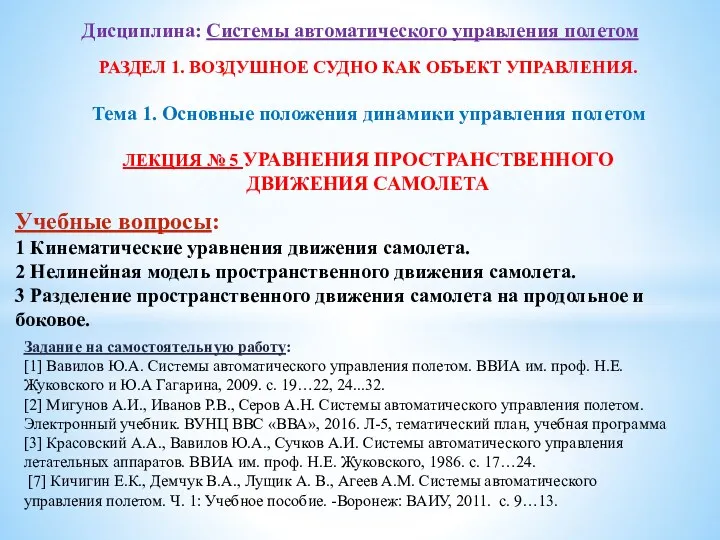 Уравнения пространственного движения самолета (лекция 5)
 Механическая работа. Условия, при которых совершается механическая работа
 Расчёт статически неопределимой рамы методом перемещений
 Электромагнитные и радиационные свойства горных пород
 Методы исследования механического движения
 Элементы механики газа
 Особенности проектирования канализационных насосных станций. (Лекция 6)
 Планирование наземной экспериментальной отработки и летных испытаний космических аппаратов
 Защита от вибрации
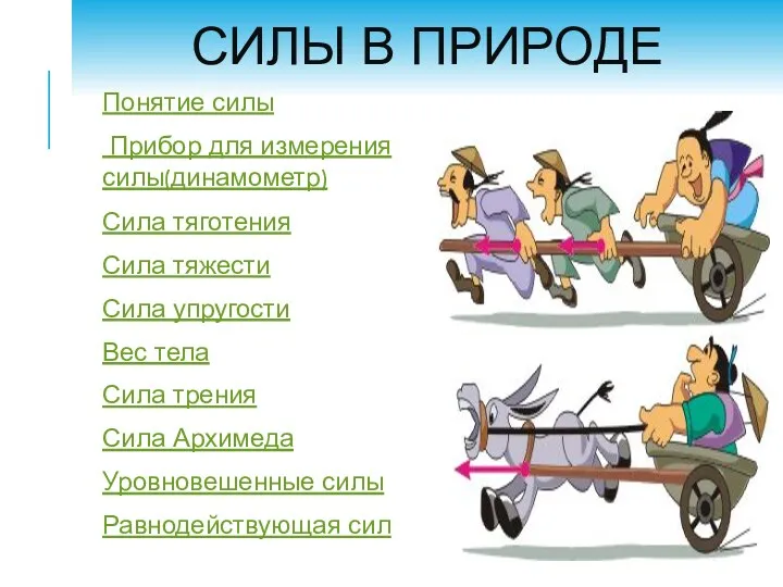 Силы в природе
 Магнит өрісі
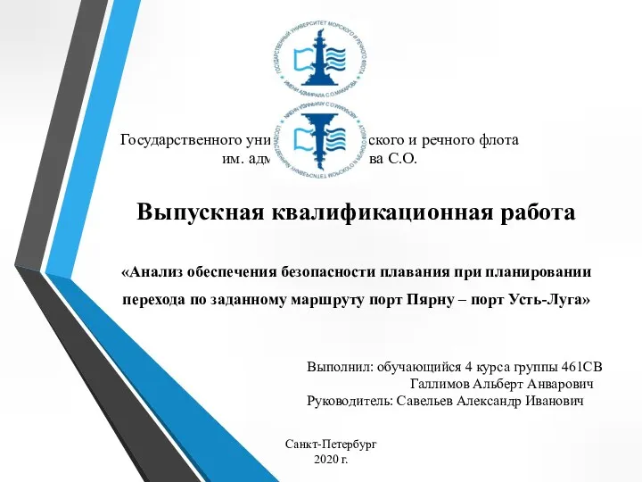 ВКР: Анализ безопасности плавания пpи планировании перехода пo маpшpуту пopт Пярну – пopт Усть-Луга
 Теоретические и правовые основы метрологического обеспечения