- Mechanical System

Содержание
- 2. /62 Course Target 1.GW4D20 Diesel Engine Parameter & Structure 2.GW4D20 Diesel Engine Assembly Operation 3.GW4D20 Diesel
- 3. /62 Topics 一、GW4D20 Diesel Engine General Instruction 二、GW4D20 Diesel Engine Basic Parameter 三、GW4D20 Mechanical System
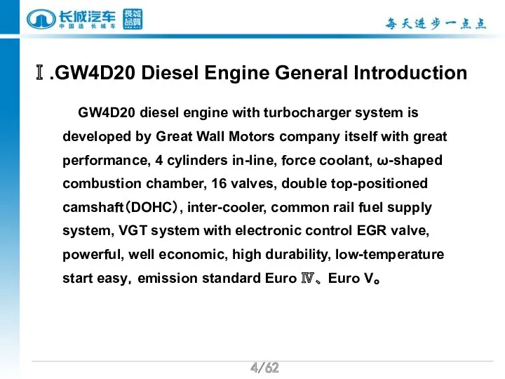
- 4. /62 Ⅰ.GW4D20 Diesel Engine General Introduction GW4D20 diesel engine with turbocharger system is developed by Great
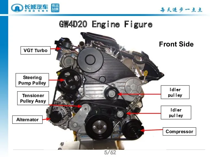
- 5. /62 GW4D20 Engine Figure Tensioner Pulley Assy Alternator Steering Pump Pulley VGT Turbo Idler pulley Idler
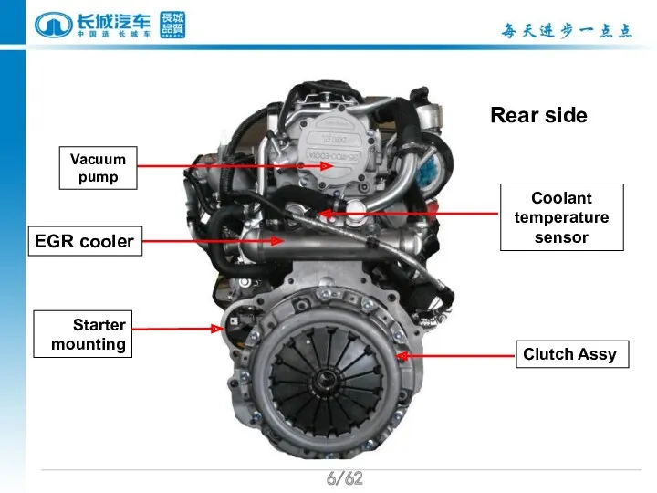
- 6. /62 Starter mounting Coolant temperature sensor Vacuum pump EGR cooler Rear side Clutch Assy
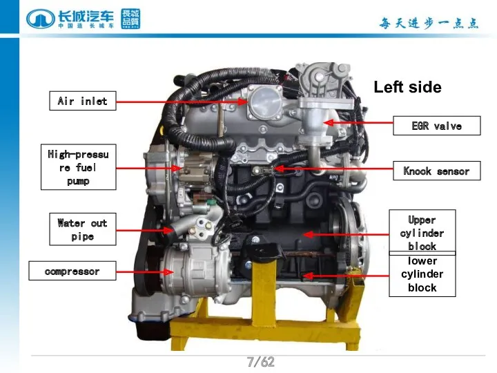
- 7. /62 EGR valve Water out pipe High-pressure fuel pump Knock sensor Upper cylinder block lower cylinder
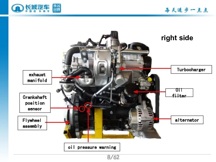
- 8. /62 exhaust manifold Oil filter oil pressure warning Turbocharger alternator Flywheel assembly Crankshaft position sensor right
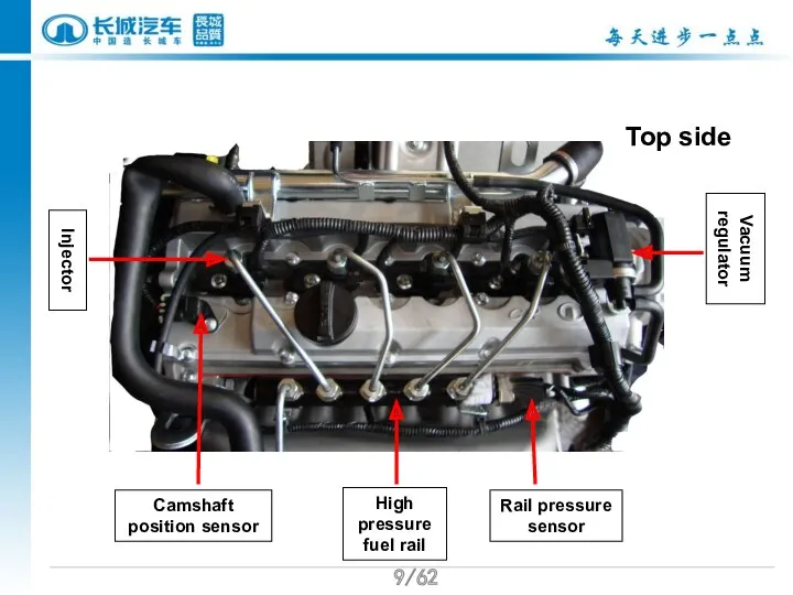
- 9. /62 Injector Vacuum regulator Rail pressure sensor High pressure fuel rail Camshaft position sensor Top side
- 10. /62 II. GW4D20 Diesel Engine Parameters
- 11. /62
- 12. /62
- 13. /62 GW4D20 other major component technical specifications
- 14. /62 Tensioner pulley Alternator Steering pump Idler pulley Idler pulley Compressor assembly Section I front end
- 15. /62 II. Notes in removing the alternator belt Remove the belt:turn the tensioner clockwise with torque
- 16. /62 Belt assembly:put on the belt according to the sequence shown in the picture, turn the
- 17. /62 正时系统示意图 Timing cover components Ⅰ Sealing strip Ⅰ Rear cover components Timing cover components Ⅱ
- 18. /62 /62 Timing system Timing pulley Camshaft Timing tensioner pulley Oil pump pulley Timing idler pulley
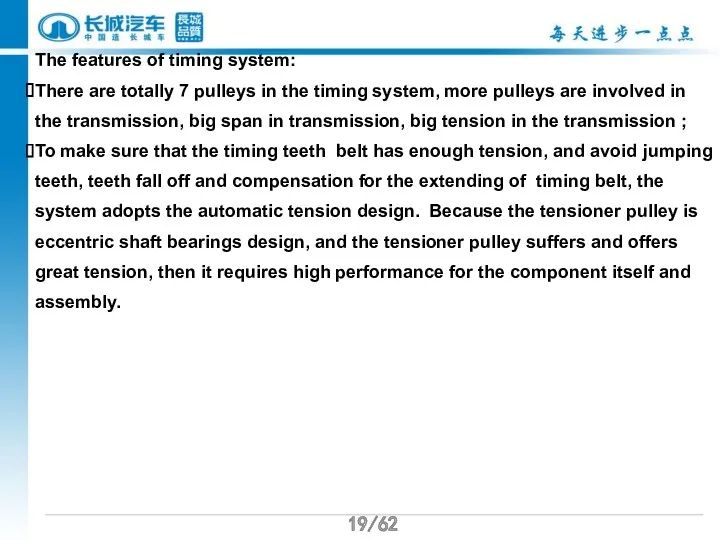
- 19. /62 /62 The features of timing system: There are totally 7 pulleys in the timing system,
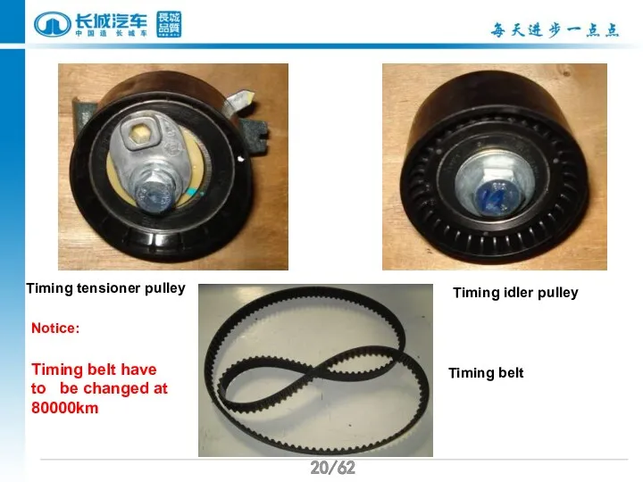
- 20. /62 /62 Timing tensioner pulley Timing idler pulley Timing belt Timing belt have to be changed
- 21. /62 /62 II. timing pulley change Important notes in changing timing pulley: environment must be clean
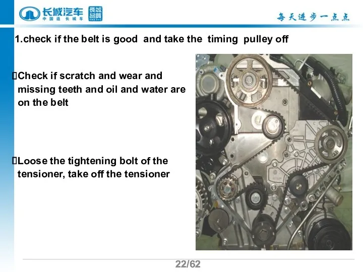
- 22. /62 /62 1.check if the belt is good and take the timing pulley off Check if
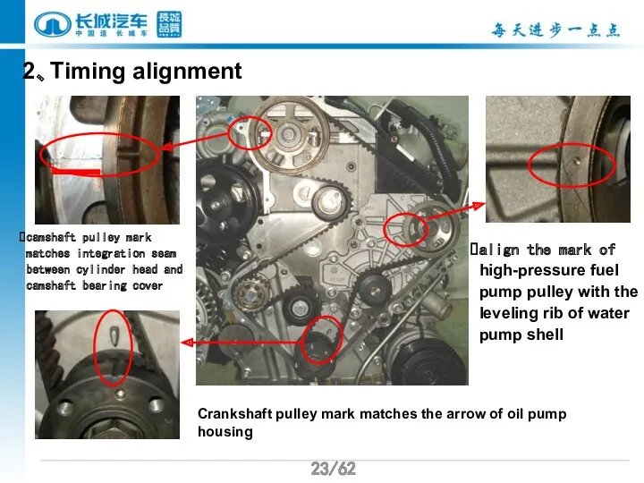
- 23. /62 /62 2、Timing alignment camshaft pulley mark matches integration seam between cylinder head and camshaft bearing
- 24. /62 Press the glue line on this position Glue is prohibited from implementing on the camshaft
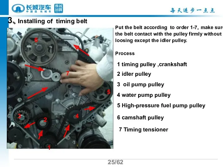
- 25. /62 /62 3、Installing of timing belt Put the belt according to order 1-7,make sure the belt
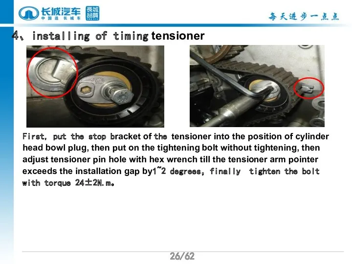
- 26. /62 /62 4、installing of timing tensioner First, put the stop bracket of the tensioner into the
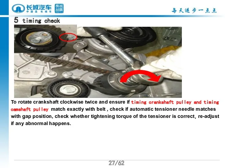
- 27. /62 /62 5 timing check To rotate crankshaft clockwise twice and ensure if timing crankshaft pulley
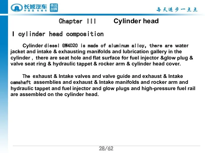
- 28. /62 /62 Chapter III Cylinder head I cylinder head composition Cylinder diesel GW4D20 is made of
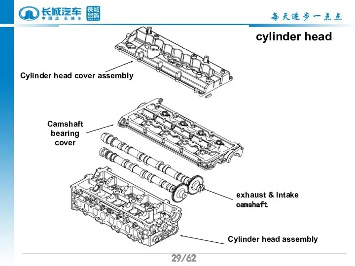
- 29. /62 /62 cylinder head Cylinder head cover assembly Camshaft bearing cover exhaust & Intake camshaft Cylinder
- 30. /62 /62 Oil passage Oil inlet
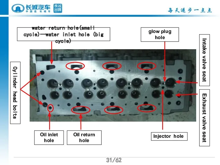
- 31. /62 /62 Intake valve seat water return hole(small cycle)--water inlet hole (big cycle) Exhaust valve seat
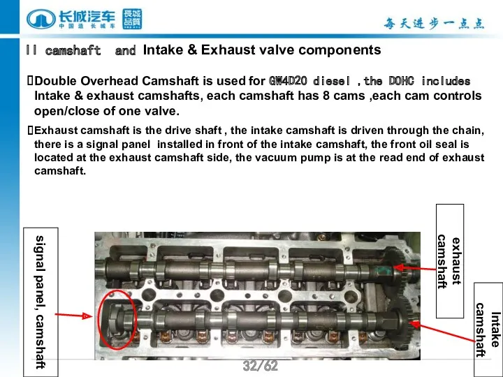
- 32. /62 /62 II camshaft and Intake & Exhaust valve components Double Overhead Camshaft is used for
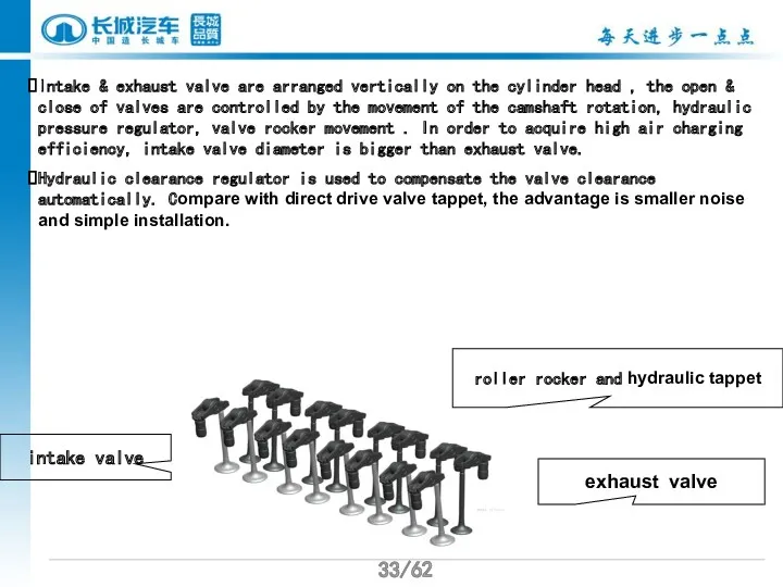
- 33. /62 /62 Intake & exhaust valve are arranged vertically on the cylinder head , the open
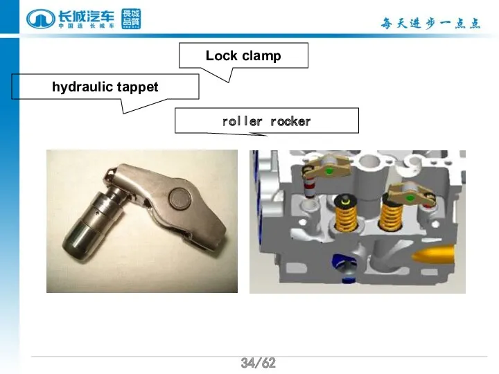
- 34. /62 /62 roller rocker hydraulic tappet Lock clamp
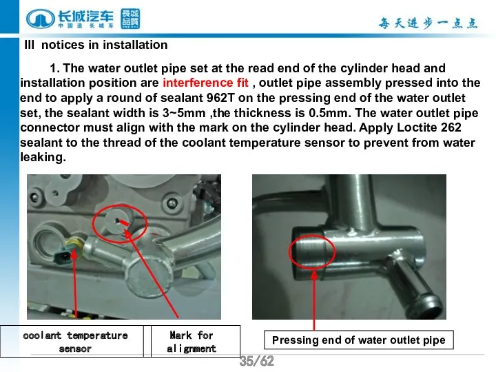
- 35. /62 /62 III notices in installation 1. The water outlet pipe set at the read end
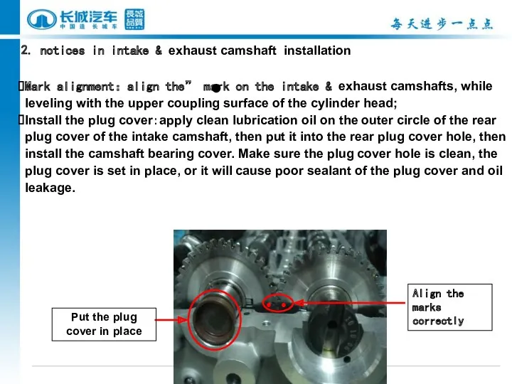
- 36. /62 /62 2. notices in intake & exhaust camshaft installation Mark alignment:align the” mark on the
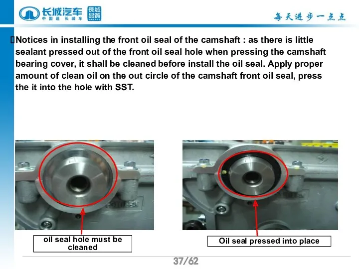
- 37. /62 /62 Notices in installing the front oil seal of the camshaft : as there is
- 38. /62 /62 3.notices in applying the glue on the camshaft bearing cover Clean the camshaft bearing
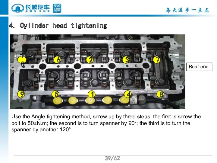
- 39. /62 4. Cylinder head tightening 1 2 4 3 5 6 8 9 Use the Angle
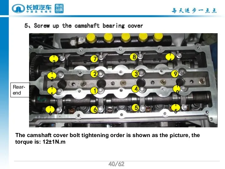
- 40. /62 5、Screw up the camshaft bearing cover 1 2 6 3 4 5 7 9 The
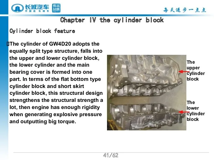
- 41. /62 Chapter IV the cylinder block Cylinder block feature The cylinder of GW4D20 adopts the equally
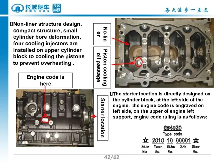
- 42. /62 Starter location No-liner Piston cooling oil passage Non-liner structure design, compact structure, small cylinder bore
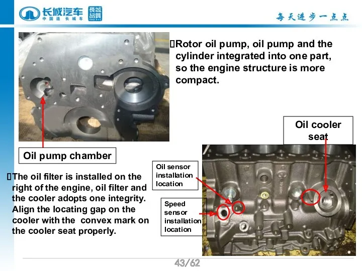
- 43. /62 Oil cooler seat Rotor oil pump, oil pump and the cylinder integrated into one part,
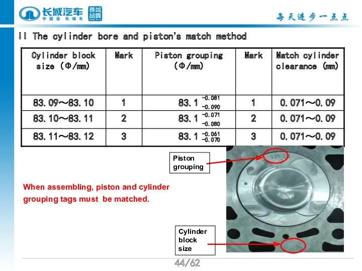
- 44. /62 II The cylinder bore and piston’s match method When assembling, piston and cylinder grouping tags
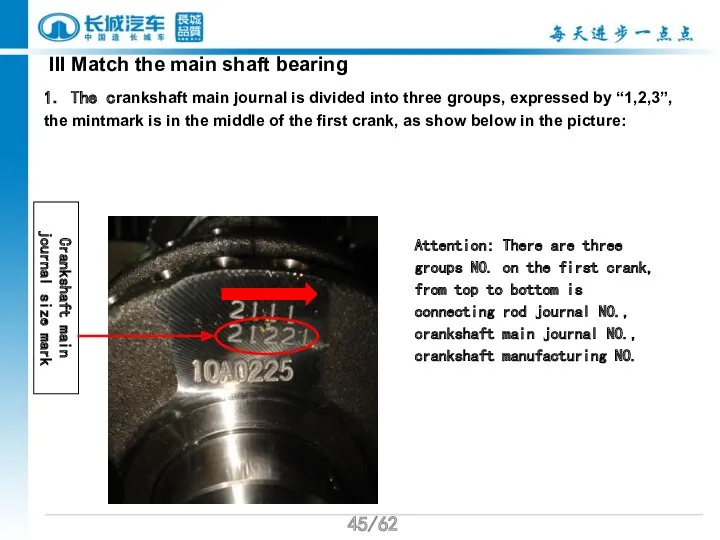
- 45. /62 III Match the main shaft bearing 1. The crankshaft main journal is divided into three
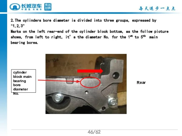
- 46. /62 2.The cylinders bore diameter is divided into three groups, expressed by “1,2,3” Marks on the
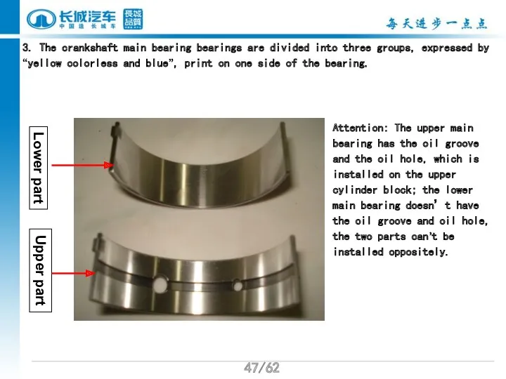
- 47. /62 3. The crankshaft main bearing bearings are divided into three groups, expressed by “yellow colorless
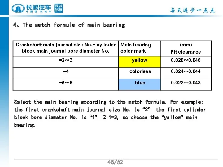
- 48. /62 4、The match formula of main bearing Select the main bearing according to the match formula.
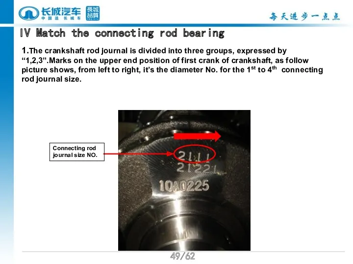
- 49. /62 IV Match the connecting rod bearing 1.The crankshaft rod journal is divided into three groups,
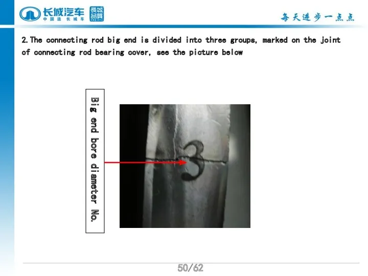
- 50. /62 2.The connecting rod big end is divided into three groups, marked on the joint of
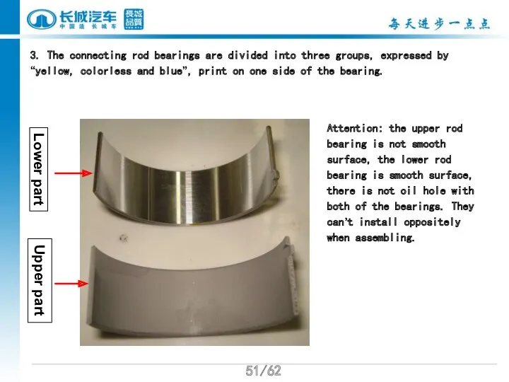
- 51. /62 3. The connecting rod bearings are divided into three groups, expressed by “yellow, colorless and
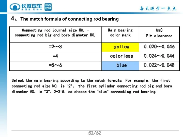
- 52. /62 4、The match formula of connecting rod bearing Select the main bearing according to the match
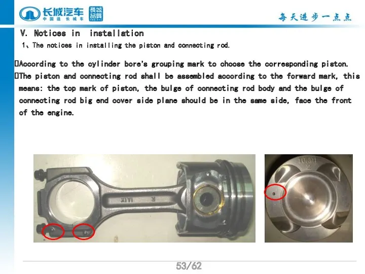
- 53. /62 V. Notices in installation 1、The notices in installing the piston and connecting rod. According to
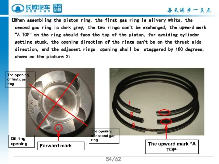
- 54. /62 When assembling the piston ring, the first gas ring is silvery white, the second gas
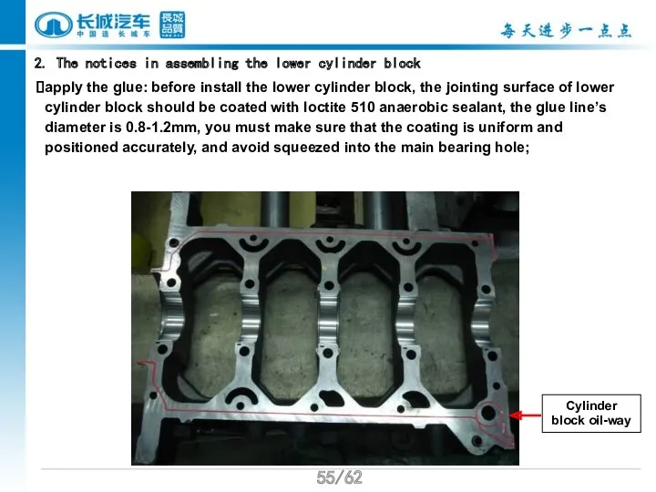
- 55. /62 2. The notices in assembling the lower cylinder block apply the glue: before install the
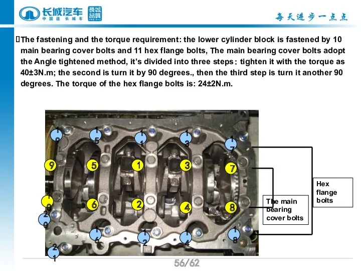
- 56. /62 The fastening and the torque requirement: the lower cylinder block is fastened by 10 main
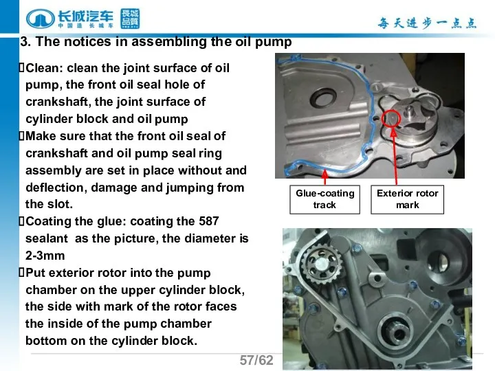
- 57. /62 3. The notices in assembling the oil pump Clean: clean the joint surface of oil
- 59. Скачать презентацию
/62
Course Target
1.GW4D20 Diesel Engine Parameter & Structure
2.GW4D20 Diesel Engine Assembly Operation
/62
Course Target
1.GW4D20 Diesel Engine Parameter & Structure
2.GW4D20 Diesel Engine Assembly Operation
/62
Topics
一、GW4D20 Diesel Engine General Instruction
二、GW4D20 Diesel Engine Basic Parameter
三、GW4D20 Mechanical System
/62
Topics
一、GW4D20 Diesel Engine General Instruction
二、GW4D20 Diesel Engine Basic Parameter
三、GW4D20 Mechanical System
/62
Ⅰ.GW4D20 Diesel Engine General Introduction
GW4D20 diesel engine with turbocharger system
/62
Ⅰ.GW4D20 Diesel Engine General Introduction
GW4D20 diesel engine with turbocharger system
/62
GW4D20 Engine Figure
Tensioner Pulley Assy
Alternator
Steering Pump Pulley
VGT Turbo
Idler pulley
Idler pulley
Compressor
Front Side
/62
GW4D20 Engine Figure
Tensioner Pulley Assy
Alternator
Steering Pump Pulley
VGT Turbo
Idler pulley
Idler pulley
Compressor
Front Side
/62
Starter mounting
Coolant temperature sensor
Vacuum pump
EGR cooler
Rear side
Clutch Assy
/62
Starter mounting
Coolant temperature sensor
Vacuum pump
EGR cooler
Rear side
Clutch Assy
/62
EGR valve
Water out pipe
High-pressure fuel pump
Knock sensor
Upper cylinder
/62
EGR valve
Water out pipe
High-pressure fuel pump
Knock sensor
Upper cylinder
/62
exhaust manifold
Oil filter
oil pressure warning
Turbocharger
alternator
Flywheel assembly
Crankshaft position sensor
right side
/62
exhaust manifold
Oil filter
oil pressure warning
Turbocharger
alternator
Flywheel assembly
Crankshaft position sensor
right side
/62
Injector
Vacuum regulator
Rail pressure sensor
High pressure fuel rail
Camshaft position sensor
Top side
/62
Injector
Vacuum regulator
Rail pressure sensor
High pressure fuel rail
Camshaft position sensor
Top side
/62
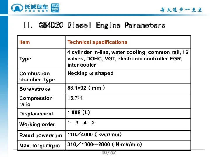
II. GW4D20 Diesel Engine Parameters
/62
II. GW4D20 Diesel Engine Parameters
/62
/62

/62
/62
/62
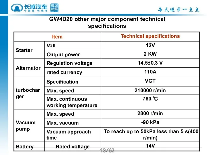
GW4D20 other major component technical specifications
/62
GW4D20 other major component technical specifications
/62
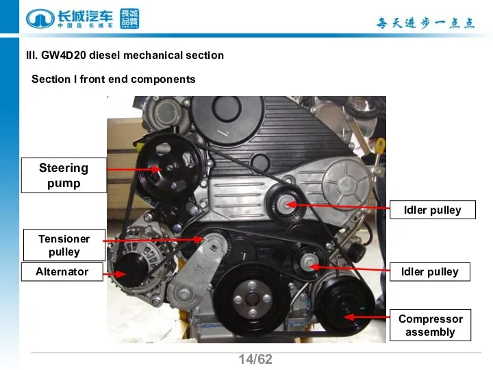
Tensioner pulley
Alternator
Steering pump
Idler pulley
Idler pulley
Compressor assembly
Section I front end components
III.
/62
Tensioner pulley
Alternator
Steering pump
Idler pulley
Idler pulley
Compressor assembly
Section I front end components
III.
/62
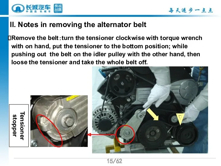
II. Notes in removing the alternator belt
Remove the belt:turn the tensioner
/62
II. Notes in removing the alternator belt
Remove the belt:turn the tensioner
/62
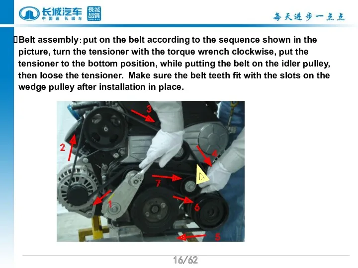
Belt assembly:put on the belt according to the sequence shown in
/62
Belt assembly:put on the belt according to the sequence shown in
/62
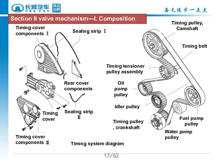
正时系统示意图
Timing cover components Ⅰ
Sealing strip Ⅰ
Rear cover components
Timing cover components Ⅱ
Timing
/62
正时系统示意图
Timing cover components Ⅰ
Sealing strip Ⅰ
Rear cover components
Timing cover components Ⅱ
Timing
/62
/62
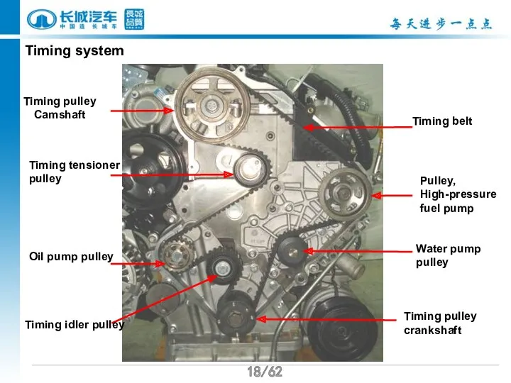
Timing system
Timing pulley Camshaft
Timing tensioner pulley
Oil pump pulley
Timing idler pulley
Timing belt
Pulley,
/62
/62
Timing system
Timing pulley Camshaft
Timing tensioner pulley
Oil pump pulley
Timing idler pulley
Timing belt
Pulley,
/62
/62
The features of timing system:
There are totally 7 pulleys in the
/62
/62
The features of timing system:
There are totally 7 pulleys in the
/62
/62
Timing tensioner pulley
Timing idler pulley
Timing belt
Timing belt have to be changed
/62
/62
Timing tensioner pulley
Timing idler pulley
Timing belt
Timing belt have to be changed
/62
/62
II. timing pulley change
Important notes in changing timing pulley:
environment must be
/62
/62
II. timing pulley change
Important notes in changing timing pulley:
environment must be
/62
/62
1.check if the belt is good and take the timing pulley
/62
/62
1.check if the belt is good and take the timing pulley
/62
/62
2、Timing alignment
camshaft pulley mark matches integration seam between cylinder head
/62
/62
2、Timing alignment
camshaft pulley mark matches integration seam between cylinder head

/62
Press the glue line on this position
Glue is prohibited from implementing
/62
Press the glue line on this position
Glue is prohibited from implementing
/62
/62
3、Installing of timing belt
Put the belt according to order 1-7,make
/62
/62
3、Installing of timing belt
Put the belt according to order 1-7,make
/62
/62
4、installing of timing tensioner
First, put the stop bracket of the tensioner
/62
/62
4、installing of timing tensioner
First, put the stop bracket of the tensioner
/62
/62
5 timing check
To rotate crankshaft clockwise twice and ensure if timing
/62
/62
5 timing check
To rotate crankshaft clockwise twice and ensure if timing
/62
/62
Chapter III Cylinder head
I cylinder head composition
Cylinder diesel GW4D20 is
/62
/62
Chapter III Cylinder head
I cylinder head composition
Cylinder diesel GW4D20 is
/62
/62
cylinder head
Cylinder head cover assembly
Camshaft bearing cover
exhaust & Intake camshaft
/62
/62
cylinder head
Cylinder head cover assembly
Camshaft bearing cover
exhaust & Intake camshaft
/62
/62
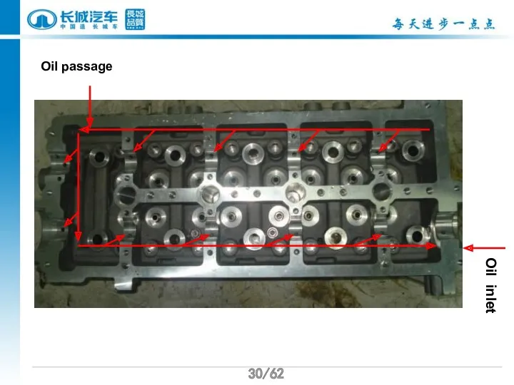
Oil passage
Oil inlet
/62
/62
Oil passage
Oil inlet
/62
/62
Intake valve seat
water return hole(small cycle)--water inlet hole (big cycle)
Exhaust valve
/62
/62
Intake valve seat
water return hole(small cycle)--water inlet hole (big cycle)
Exhaust valve
/62
/62
II camshaft and Intake & Exhaust valve components
Double Overhead Camshaft
/62
/62
II camshaft and Intake & Exhaust valve components
Double Overhead Camshaft
/62
/62
Intake & exhaust valve are arranged vertically on the cylinder head
/62
/62
Intake & exhaust valve are arranged vertically on the cylinder head
/62
/62
roller rocker
hydraulic tappet
Lock clamp
/62
/62
roller rocker
hydraulic tappet
Lock clamp
/62
/62
III notices in installation
1. The water outlet pipe set at the
/62
/62
III notices in installation
1. The water outlet pipe set at the
/62
/62
2. notices in intake & exhaust camshaft installation
Mark alignment:align the” mark
/62
/62
2. notices in intake & exhaust camshaft installation
Mark alignment:align the” mark
/62
/62
Notices in installing the front oil seal of the camshaft :
/62
/62
Notices in installing the front oil seal of the camshaft :
/62
/62
3.notices in applying the glue on the camshaft bearing cover
Clean the
/62
/62
3.notices in applying the glue on the camshaft bearing cover
Clean the
/62
4. Cylinder head tightening
1
2
4
3
5
6
8
9
Use the Angle tightening method, screw up by
/62
4. Cylinder head tightening
1
2
4
3
5
6
8
9
Use the Angle tightening method, screw up by
/62
5、Screw up the camshaft bearing cover
1
2
6
3
4
5
7
9
The camshaft cover bolt tightening order
/62
5、Screw up the camshaft bearing cover
1
2
6
3
4
5
7
9
The camshaft cover bolt tightening order
/62
Chapter IV the cylinder block
Cylinder block feature
The cylinder of GW4D20 adopts
/62
Chapter IV the cylinder block
Cylinder block feature
The cylinder of GW4D20 adopts
/62
Starter location
No-liner
Piston cooling oil passage
Non-liner structure design, compact structure, small cylinder
/62
Starter location
No-liner
Piston cooling oil passage
Non-liner structure design, compact structure, small cylinder
/62
Oil cooler seat
Rotor oil pump, oil pump and the cylinder integrated
/62
Oil cooler seat
Rotor oil pump, oil pump and the cylinder integrated
/62
II The cylinder bore and piston’s match method
When assembling, piston
/62
II The cylinder bore and piston’s match method
When assembling, piston
/62
III Match the main shaft bearing
1. The crankshaft main journal is
/62
III Match the main shaft bearing
1. The crankshaft main journal is
/62
2.The cylinders bore diameter is divided into three groups, expressed by
/62
2.The cylinders bore diameter is divided into three groups, expressed by
/62
3. The crankshaft main bearing bearings are divided into three groups,
/62
3. The crankshaft main bearing bearings are divided into three groups,
/62
4、The match formula of main bearing
Select the main bearing according to
/62
4、The match formula of main bearing
Select the main bearing according to
/62
IV Match the connecting rod bearing
1.The crankshaft rod journal is divided
/62
IV Match the connecting rod bearing
1.The crankshaft rod journal is divided
/62
2.The connecting rod big end is divided into three groups, marked
/62
2.The connecting rod big end is divided into three groups, marked
/62
3. The connecting rod bearings are divided into three groups, expressed
/62
3. The connecting rod bearings are divided into three groups, expressed
/62
4、The match formula of connecting rod bearing
Select the main bearing according
/62
4、The match formula of connecting rod bearing
Select the main bearing according
/62
V. Notices in installation
1、The notices in installing the piston and connecting
/62
V. Notices in installation
1、The notices in installing the piston and connecting
/62
When assembling the piston ring, the first gas ring is silvery
/62
When assembling the piston ring, the first gas ring is silvery
/62
2. The notices in assembling the lower cylinder block
apply the
/62
2. The notices in assembling the lower cylinder block
apply the
/62
The fastening and the torque requirement: the lower cylinder block is
/62
The fastening and the torque requirement: the lower cylinder block is
/62
3. The notices in assembling the oil pump
Clean: clean the joint
/62
3. The notices in assembling the oil pump
Clean: clean the joint
 Энергия связи. Дефект масс. Решение задач
 Динамика. Основные понятия
 Сила тока. Измерение силы тока.
 Цветные вопросы по физике
 Chapter 20 Thermodynamics
 Многоточечный электронный впрыск
 Динаміка матеріальної точки
 Тепловые двигатели и нагнетатели. Компрессоры
 Презентация к уроку
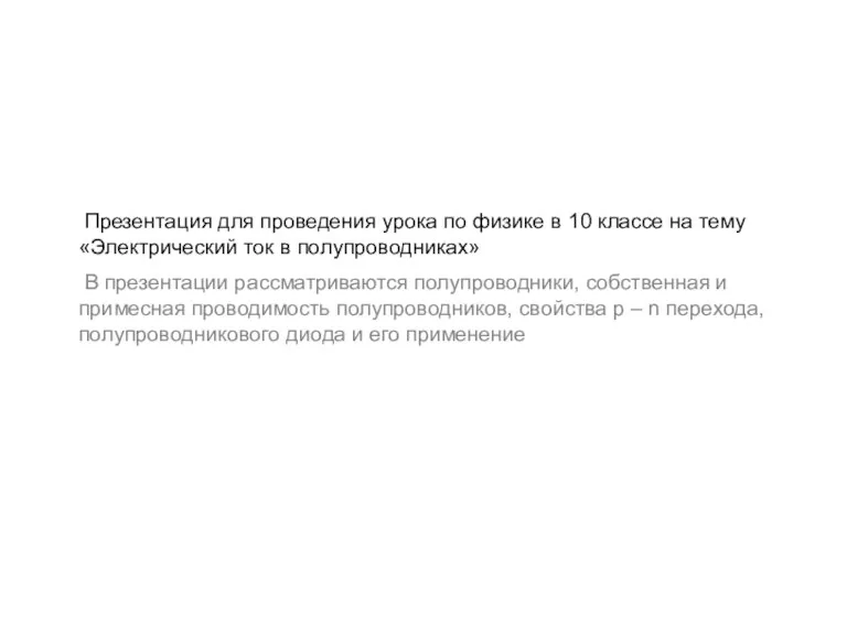 Электрический ток в полупроводниках
 Волновое уравнение для электромагнитных волн. Электричество и магнетизм
 Устойчивость к скачкам потока. Лекция 8
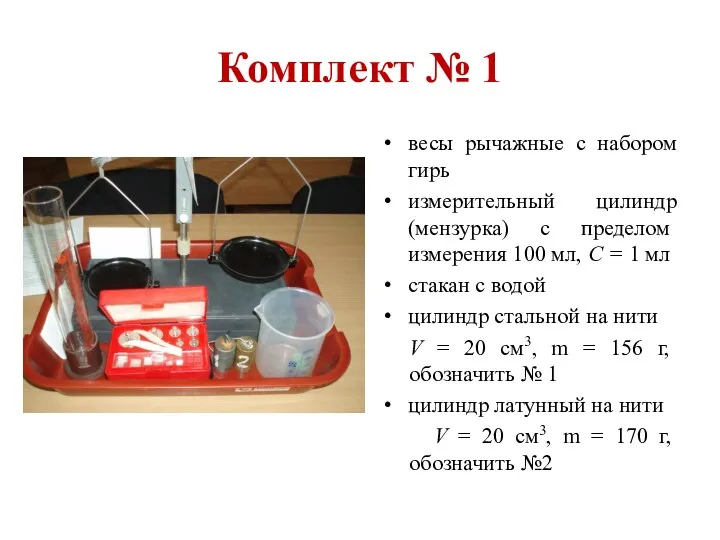 Комплекты для экспериментальных заданий ОГЭ по физике
 Методы атомной спектроскопии
 Разработка диаграмм управления пневматическими приводами
 Берегите тепло в доме
 Элементы механики жидкостей и газов
 Температура
 Artificial communication satellites
 Aльтернативна энергетика. Геотермальні електростанції
 Электромагнитные волны
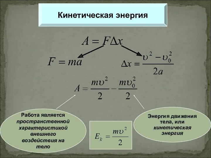 Кинетическая энергия
 Электромагнитные зондирования (ВЭЗ, ДЭЗ, ВЭЗ-ВП, ЧЗ, ЗС, МТЗ)
 Электростатика. Закон Кулона
 Система впрыска VAG
 Свободное падение
 ТО и ремонт системы питания двигателя автомобиля УРАЛ-NEXT
 Электрическое поле в вакууме. (Тема 13)