- NW Rapid Site Installation

Содержание
- 2. Typical NW Rapid plant layout
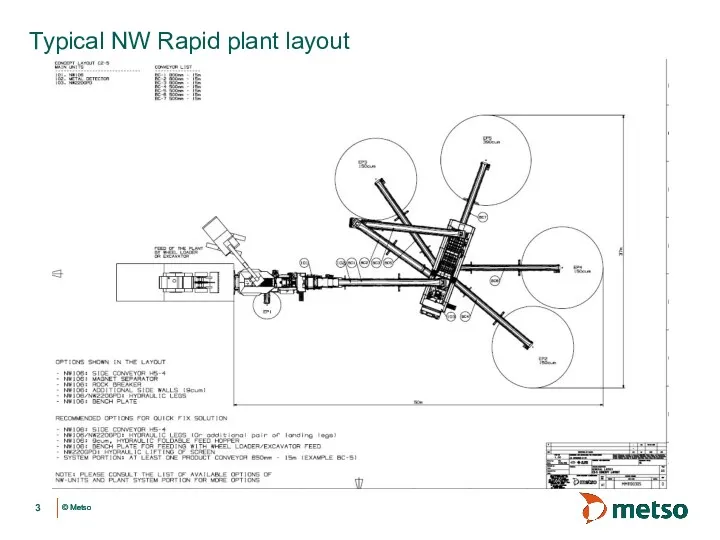
- 3. Typical NW Rapid plant layout
- 4. Co-ordinate marking as per layout Centre line of Crusher
- 5. Positioning of the NW chassis Drive in the NW, align the NW with respect to centre
- 6. Support the NW on Hydraulic legs Support the NW on Landing Legs. De-couple the Horse Place
- 7. Support the NW on Hydraulic legs 3 3 Note : Operate alternate legs and keep the
- 8. Support the NW on Hydraulic legs Operation of Hydraulic Legs Lock Pin Operate (inching) the hydraulic
- 9. Support the NW on Hydraulic legs Turn the lock plate upward and disengage from rack. Put
- 10. Support the NW on Hydraulic legs Level the NW chassis 1470 mm
- 11. Unfold the hand rails
- 12. Install Screen drive
- 13. Lift the screen Transport Work All the Screen springs must be locked by using screen transport
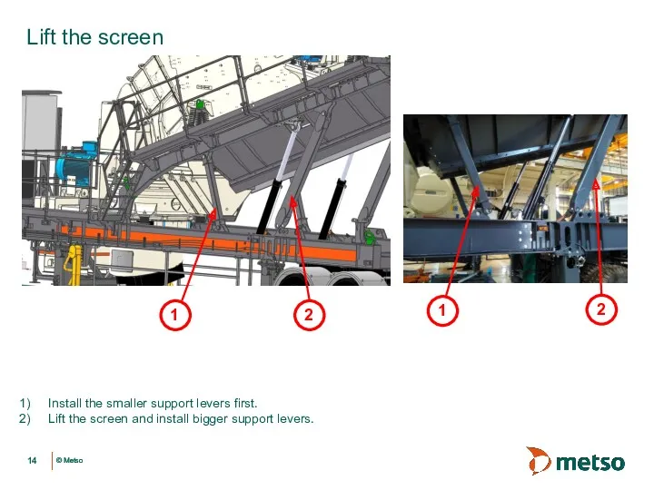
- 14. Lift the screen Install the smaller support levers first. Lift the screen and install bigger support
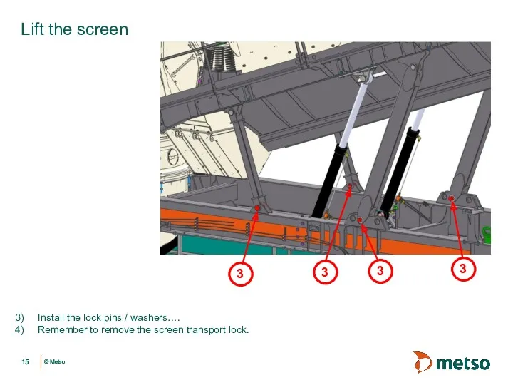
- 15. Lift the screen Install the lock pins / washers…. Remember to remove the screen transport lock.
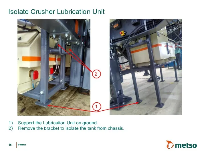
- 16. Isolate Crusher Lubrication Unit Support the Lubrication Unit on ground. Remove the bracket to isolate the
- 17. Set the dividing hopper gate as per process requirement
- 18. Date Author Title Set Up Cavity Level Sensor
- 19. Date Author Title Isolate the Control Centre from NW chassis. Remove the mounting bolts and support
- 20. Electrical Installation
- 21. Date Author Title Electrical Installation Connect Screen motor power cable.
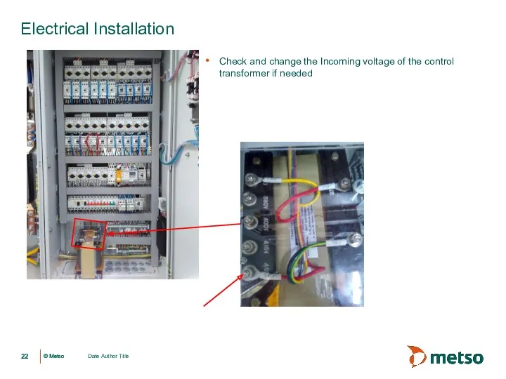
- 22. Date Author Title Electrical Installation Check and change the Incoming voltage of the control transformer if
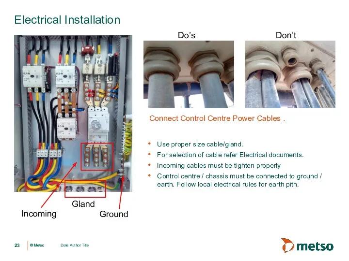
- 23. Date Author Title Connect Control Centre Power Cables . Do’s Don’t Use proper size cable/gland. For
- 24. Plant Conveyor connection Electrical Installation Power Safety switch Refer Electrical Circuit diagram for Plant Conveyor connection
- 25. IC50C Parameters to be set as pet plant layout and feed arrangement Electrical Installation
- 27. Скачать презентацию
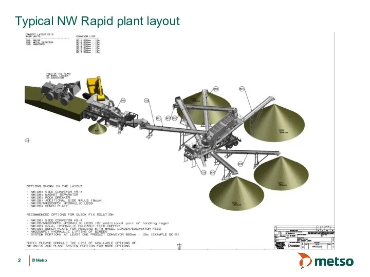
Typical NW Rapid plant layout
Typical NW Rapid plant layout
Typical NW Rapid plant layout
Typical NW Rapid plant layout
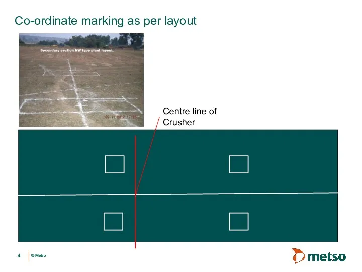
Co-ordinate marking as per layout
Centre line of Crusher
Co-ordinate marking as per layout
Centre line of Crusher
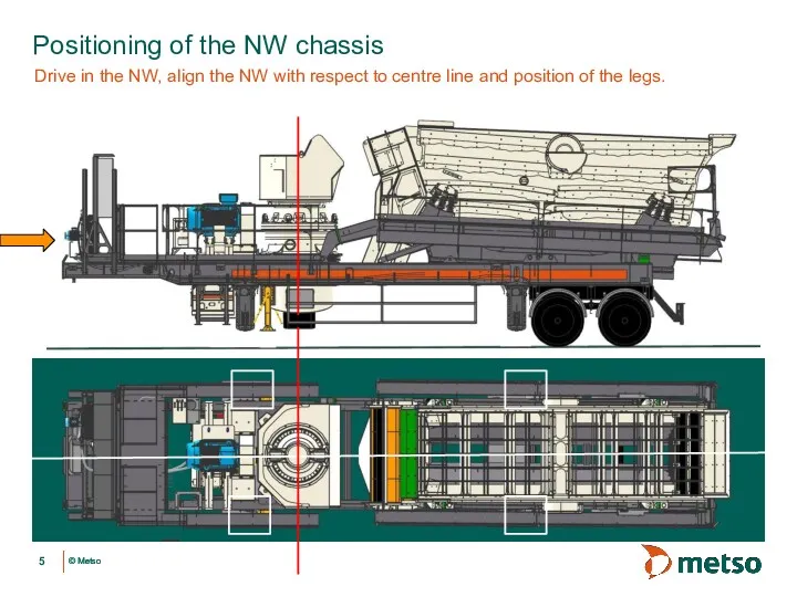
Positioning of the NW chassis
Drive in the NW, align the NW
Positioning of the NW chassis
Drive in the NW, align the NW
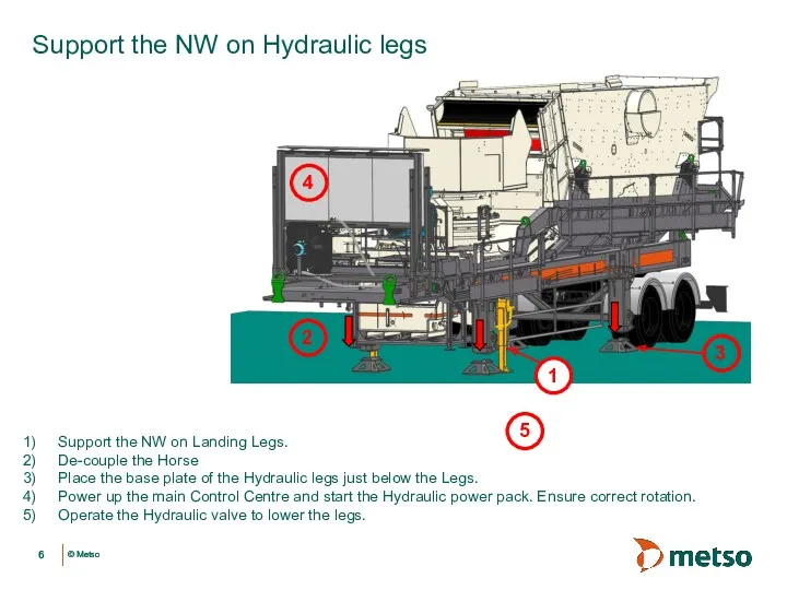
Support the NW on Hydraulic legs
Support the NW on Landing Legs.
De-couple
Support the NW on Hydraulic legs
Support the NW on Landing Legs.
De-couple
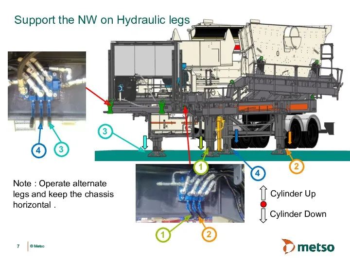
Support the NW on Hydraulic legs
3
3
Note : Operate alternate legs and
Support the NW on Hydraulic legs
3
3
Note : Operate alternate legs and
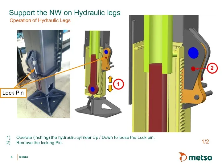
Support the NW on Hydraulic legs
Operation of Hydraulic Legs
Lock Pin
Operate (inching)
Support the NW on Hydraulic legs
Operation of Hydraulic Legs
Lock Pin
Operate (inching)
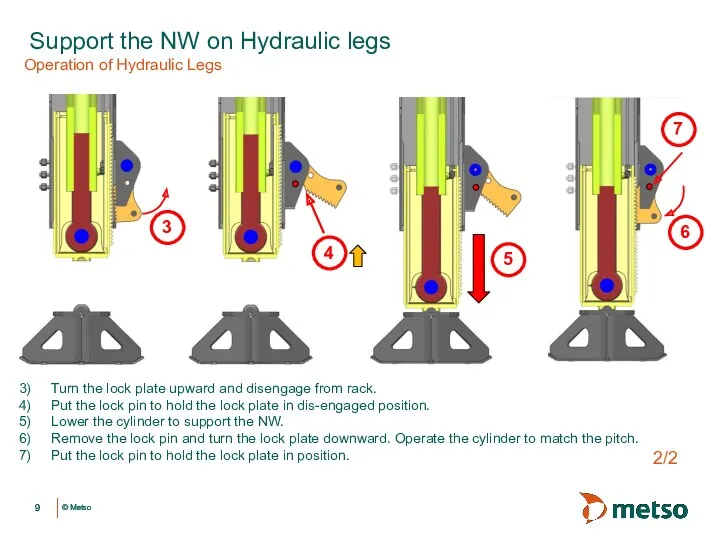
Support the NW on Hydraulic legs
Turn the lock plate upward and
Support the NW on Hydraulic legs
Turn the lock plate upward and
Support the NW on Hydraulic legs
Level the NW chassis
1470 mm
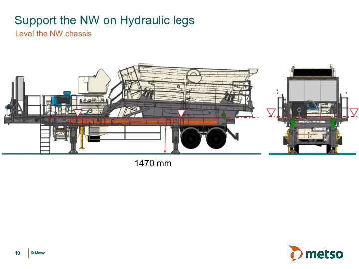
Support the NW on Hydraulic legs
Level the NW chassis
1470 mm
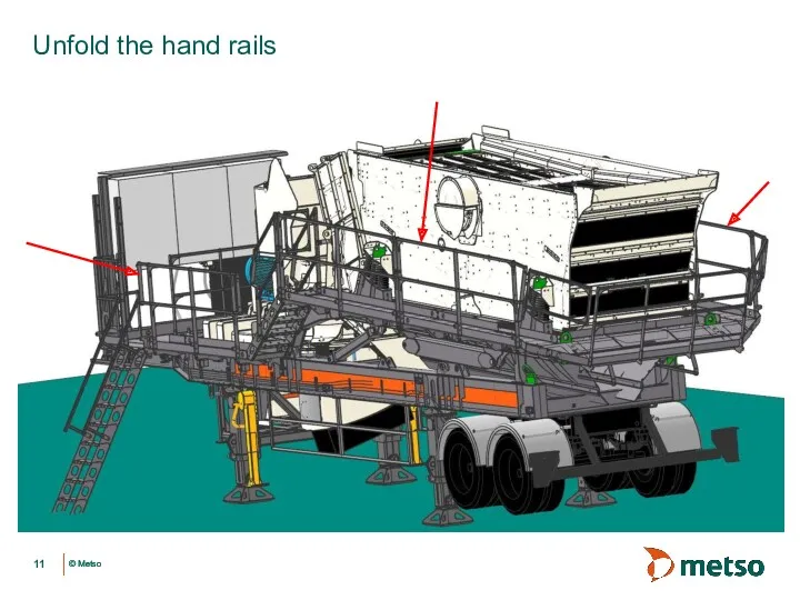
Unfold the hand rails
Unfold the hand rails
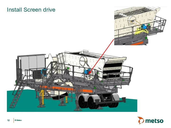
Install Screen drive
Install Screen drive
Lift the screen
Transport
Work
All the Screen springs must be locked by
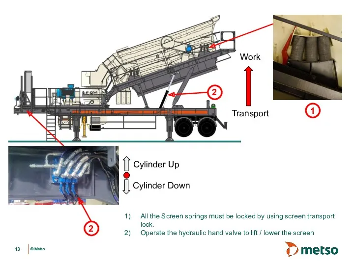
Lift the screen
Transport
Work
All the Screen springs must be locked by
Lift the screen
Install the smaller support levers first.
Lift the screen
Lift the screen
Install the smaller support levers first.
Lift the screen
Lift the screen
Install the lock pins / washers….
Remember to remove
Lift the screen
Install the lock pins / washers….
Remember to remove
Isolate Crusher Lubrication Unit
Support the Lubrication Unit on ground.
Remove the bracket
Isolate Crusher Lubrication Unit
Support the Lubrication Unit on ground.
Remove the bracket
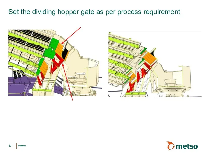
Set the dividing hopper gate as per process requirement
Set the dividing hopper gate as per process requirement
Date Author Title
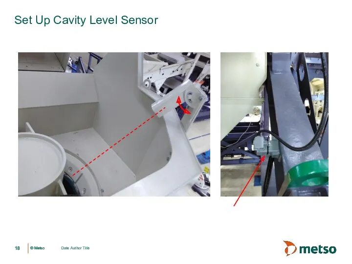
Set Up Cavity Level Sensor
Date Author Title
Set Up Cavity Level Sensor
Date Author Title
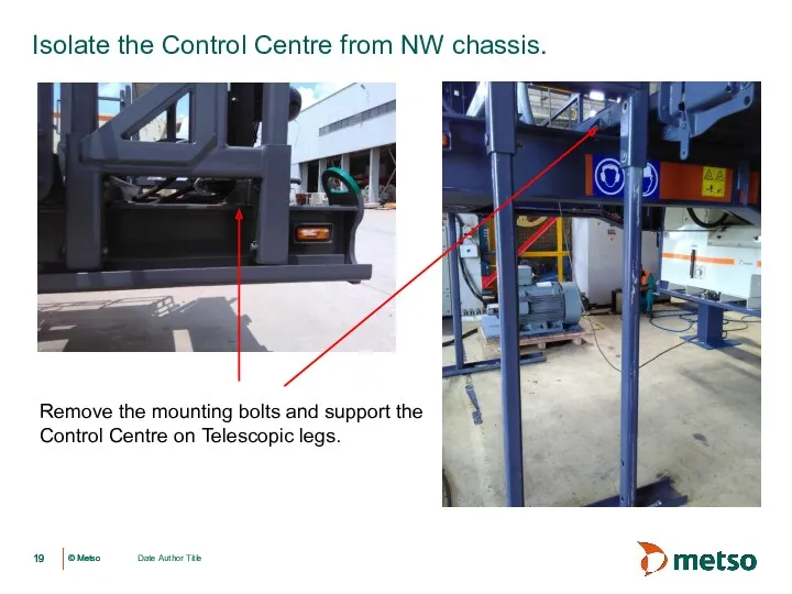
Isolate the Control Centre from NW chassis.
Remove the mounting
Date Author Title
Isolate the Control Centre from NW chassis.
Remove the mounting
Electrical Installation
Electrical Installation
Date Author Title
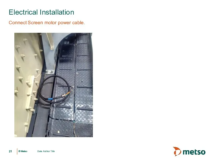
Electrical Installation
Connect Screen motor power cable.
Date Author Title
Electrical Installation
Connect Screen motor power cable.
Date Author Title
Electrical Installation
Check and change the Incoming voltage of the
Date Author Title
Electrical Installation
Check and change the Incoming voltage of the
Date Author Title
Connect Control Centre Power Cables .
Do’s
Don’t
Use proper size cable/gland.
For
Date Author Title
Connect Control Centre Power Cables .
Do’s
Don’t
Use proper size cable/gland.
For
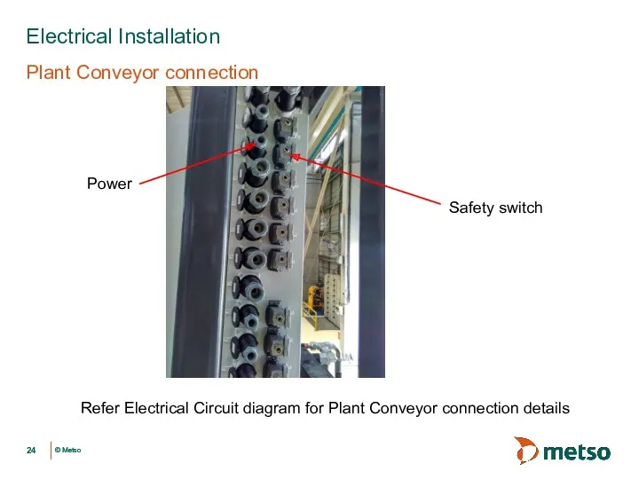
Plant Conveyor connection
Electrical Installation
Power
Safety switch
Refer Electrical Circuit diagram for Plant Conveyor
Plant Conveyor connection
Electrical Installation
Power
Safety switch
Refer Electrical Circuit diagram for Plant Conveyor
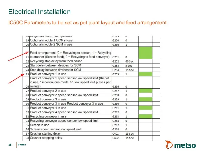
IC50C Parameters to be set as pet plant layout and feed
IC50C Parameters to be set as pet plant layout and feed
 Инженерно-авиационное обеспечение безопасности полётов
 Двигатель внутреннего сгорания
 Хроматографические методы анализа и их применение для контроля качества лекарственных средств (продолжение)
 Тормозная система КамАЗа
 Тюнинг двигателя
 Электромагнитная пушка – основа космической транспортной системы. 7 класс
 Презентация Проектное обучение
 ОГЭ - 2016. Физика.
 Основы расчета элементов стальных конструкций
 Урок Механическая работа 7 класс
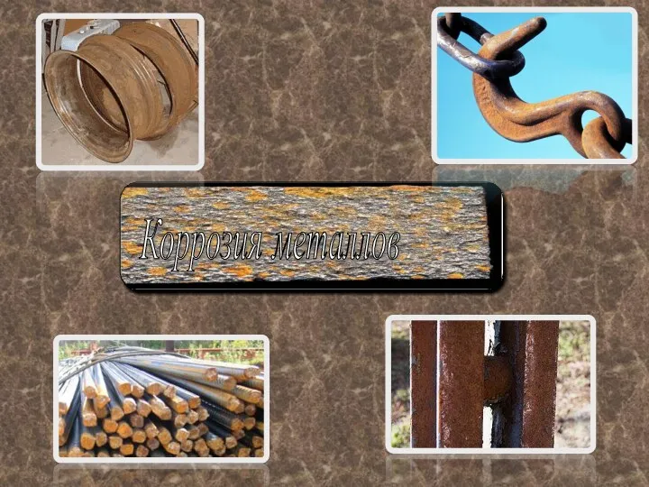 Коррозия металлов
 Простые механизмы
 Основные неисправности и нормы ТОиР. Лекция 6
 Біртекті емес электр өрісі кезіндегі разрядтың пайда болуы
 Открытый урок по физике 7 класс. Сила давления
 Полупроводники. Собственная проводимость полупроводников. Полупроводниковые приборы
 Конвективный теплообмен. Глава 2
 Инструментальные методы качественного анализа органических веществ
 Инерция
 Делимость электрического заряда. Электрон. Строение атома
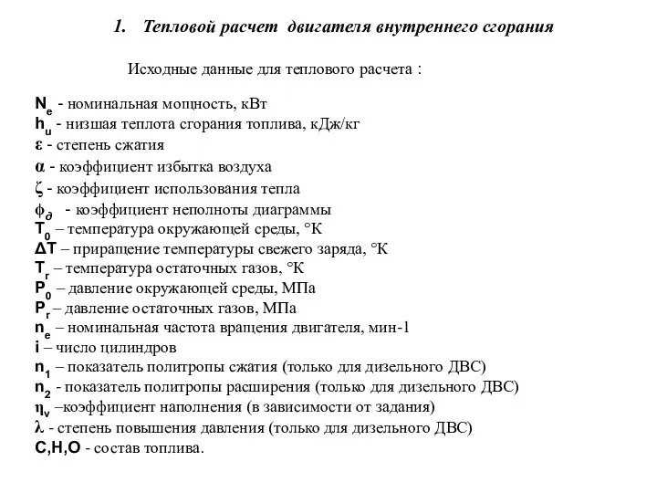 Тепловой расчет двигателя внутреннего сгорания
 Магнитное поле в вакууме
 Интеллектуальная игра по физике Умники и умницы
 Индикаторные и эффективные показатели ДВС. Тема 8
 Применение аккумуляторов
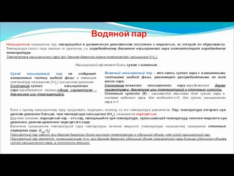 Водяной пар
 Технологии выращивания кристаллов. Технология полупроводниковых материалов
 Возникновение радио