Слайд 2Introduction
What is a PLL?
Control System Representation
Parts of a PLL
PLL in Simulink
Слайд 3What is a PLL?
Digital frequency control system
Generate high speed oscillations
Acquire and track signals
Radio
Frequency Demodulation
DX-ing
RF communications
Слайд 4Control system representation
Слайд 7Parts of a PLL
Phase Detector
Filter
Voltage Controlled Oscillator
Programmable Counter
Слайд 8Parts of a PLL
Phase Detector
Acts as comparitor
Produces a voltage proportional to the phase
difference between input and output signal
Voltage becomes a control signal
Слайд 9Parts of a PLL
Filter
Determines dynamic characteristics of PLL
Specify Capture Range (bandwidth)
Specify Tracking Range
Receives
signal from Phase Detector and filters accordingly
Слайд 10Parts of a PLL
Voltage Controlled Oscillator
Set tuning range
Set noise margin
Creates low noise clock
oscillation
Слайд 11Parts of a PLL
Divider
Divides the VCO output by the degree of the open
loop gain
Feedback loop allows phase comparison

 Обобщающий урок-игра по физике, 9 класс
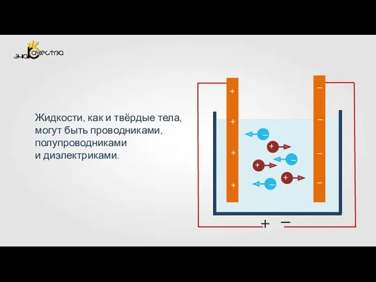 Электрический ток в жидкостях. Закон электролиза
 Релейная защита и автоматика
 Электричество и магнетизм
 Диффузия в твёрдых телах и её точечное моделирование
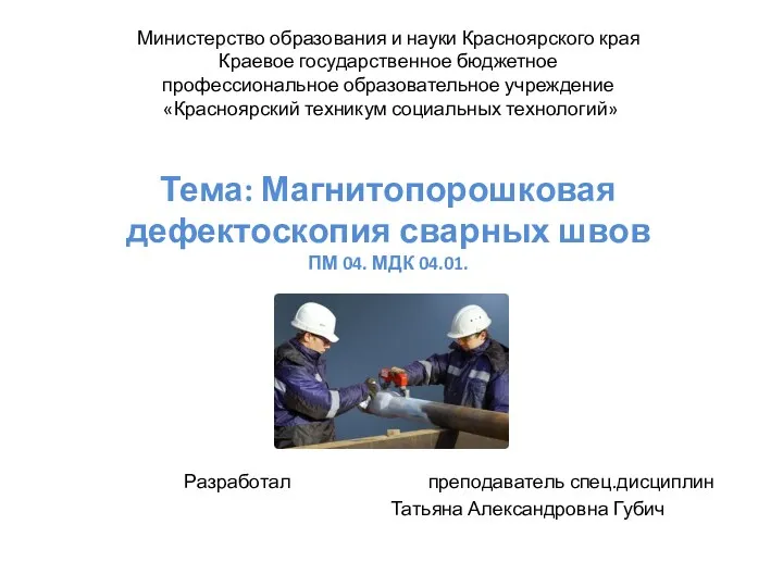 Магнитопорошковая дефектоскопия сварных швов
 Электрическое поле в вакууме. (Тема 13)
 Бүгінгі таңдағы физикалық жетістіктер. Өзінің қолтаңбасын қалдырған ғалым
 Фрикционные передачи
 Термоядерный синтез
 Тепловое излучение. Лекция 9
 The Hydrostatic Pressure. Pascal's principle. Communicating vessels. Hydraulic рress
 Презентация о Потенциальной и Кинетической энергии
 Законы постоянного тока
 Машина Голдберга
 Строительная механика. Теория определения перемещений деформируемых систем. (Часть 1. Лекция 2)
 Простые механизмы
 Радиоволны. Джеймс Максвелл
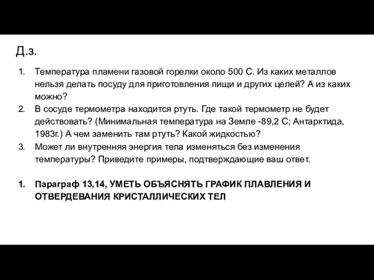 Плавление и отвердевание кристаллических тел
 Электромагнитные переходные процессы в электроэнергетических системах
 Фотоэлектронды көбейткіш, фототеристор, фототранзистор, оптотрон интегралды микросхема. Датчиктер – олардың түрлері
 Молекулярно-кинетическая теория газов. (Лекция 2)
 Проводники и диэлектрики в электростатическом поле 10 класс
 Презентация. Применение второго закона Ньютона.
 Перемещение при прямолинейном равномерном движении
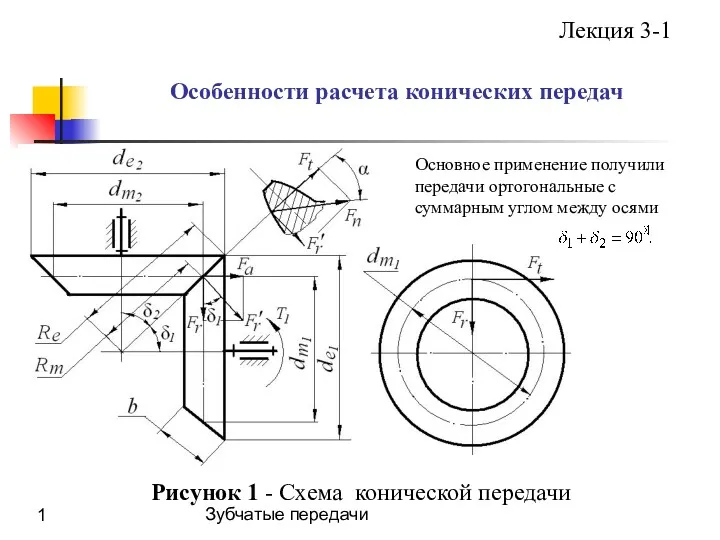 Особенности расчета конических передач. (Лекция 3.1)
 Направление тока и направление линий его магнитного поля
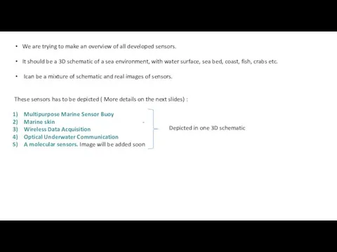 We are trying to make an overview of all developed sensors