- Practical Look to Dynamic Stability

Содержание
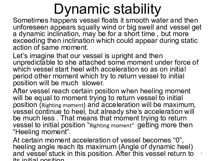
- 2. Dynamic stability Sometimes happens vessel floats it smooth water and then unforeseen appears squally wind or
- 3. Dynamic stability Under dynamic stability means ability of vessel to withstand dynamic impact of heeling moment.
- 4. Dynamic stability For to build DYNAMIC STABILITY diagram we will use formula Righting moment = GZ
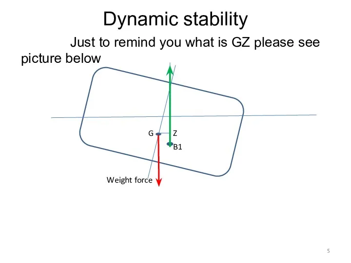
- 5. Dynamic stability Just to remind you what is GZ please see picture below G B1 Z
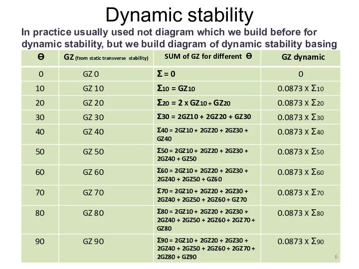
- 6. Dynamic stability In practice usually used not diagram which we build before for dynamic stability, but
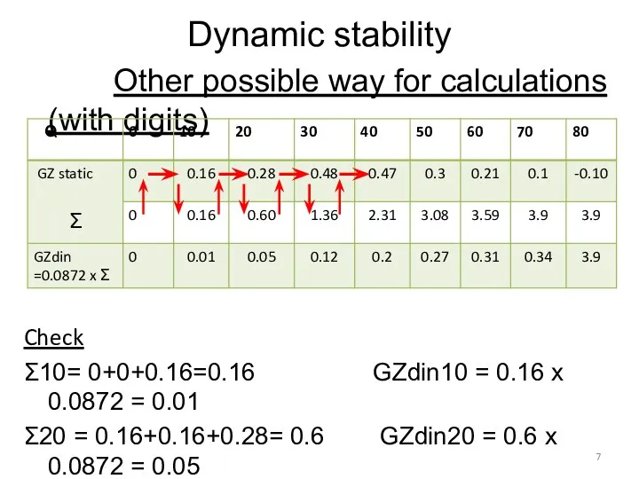
- 7. Dynamic stability Other possible way for calculations (with digits) Check Ʃ10= 0+0+0.16=0.16 GZdin10 = 0.16 x
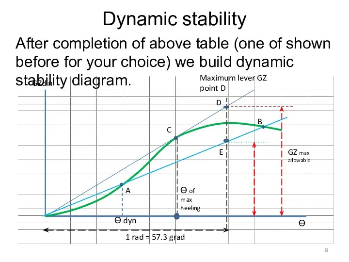
- 8. Dynamic stability After completion of above table (one of shown before for your choice) we build
- 9. Dynamic stability After all this beautiful tables and pictures certainly appears question what we can do
- 10. Dynamic stability When we build diagram of dynamic stability we expect dynamic heeling moment as permanent
- 12. Скачать презентацию
Dynamic stability
Sometimes happens vessel floats it smooth water and then unforeseen
Dynamic stability
Sometimes happens vessel floats it smooth water and then unforeseen
Dynamic stability
Under dynamic stability means ability of vessel to withstand dynamic
Dynamic stability
Under dynamic stability means ability of vessel to withstand dynamic

Dynamic stability
For to build DYNAMIC STABILITY diagram we will use
Dynamic stability
For to build DYNAMIC STABILITY diagram we will use
Dynamic stability
Just to remind you what is GZ please
Dynamic stability
Just to remind you what is GZ please
Dynamic stability
In practice usually used not diagram which we build
Dynamic stability
In practice usually used not diagram which we build
Dynamic stability
Other possible way for calculations (with digits)
Check
Ʃ10= 0+0+0.16=0.16
Dynamic stability
Other possible way for calculations (with digits)
Check
Ʃ10= 0+0+0.16=0.16
Dynamic stability
After completion of above table (one of shown before
Dynamic stability
After completion of above table (one of shown before
Dynamic stability
After all this beautiful tables and pictures certainly appears
Dynamic stability
After all this beautiful tables and pictures certainly appears

Dynamic stability
When we build diagram of dynamic stability we expect
Dynamic stability
When we build diagram of dynamic stability we expect
 Транспортирующие машины. (Лекция № 5)
 Построение эпюр внутренних сил, напряжений и деформаций растяжения-сжатия
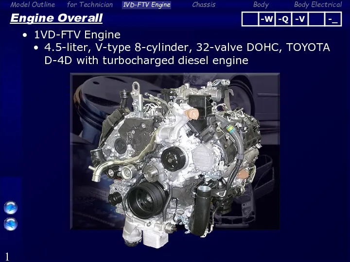 Engine overall. Model outline for technician
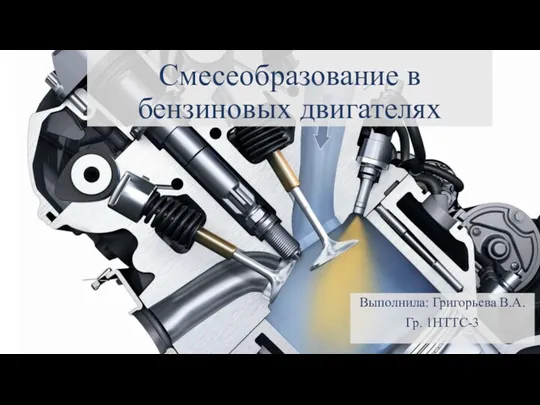 Смесеобразование в бензиновых двигателях
 Молекулярная физика. Термодинамика
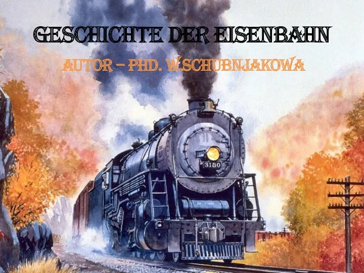 Geschichte der Eisenbahn
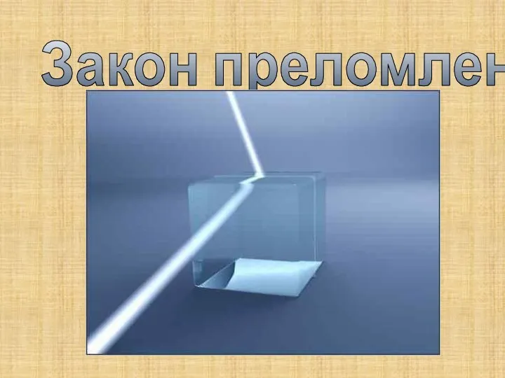 Урок Преломление света – 8 класс
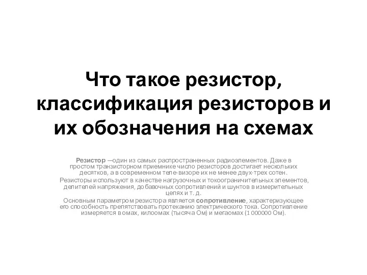 Классификация резисторов и их обозначения на схемах. (8 класс)
 Элементы оптоэлектроники. Приборы с зарядовой связью. Светодиоды. (Лекция 14.2)
 Метрология. Посадки подшипников качения
 Тормозная система Lada Priora
 Инерция. Галилео Галилей
 Экспериментальное крыло самолета ВАe 125
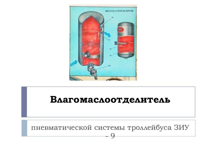 Влагомаслоотделитель пневматической системы троллейбуса ЗИУ - 9
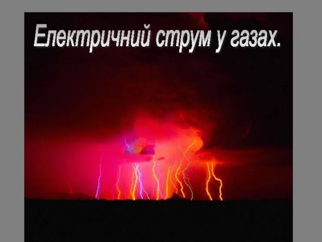 Електричний струм у газах
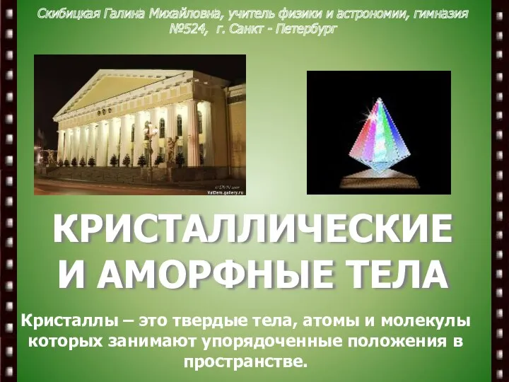 Кристаллические и аморфные тела
 Искусственные алмазы
 Инфракрасные средства обнаружения
 Мощность и работа электрического тока
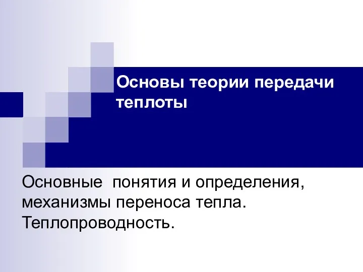 Основы теории передачи теплоты. Основные понятия и определения, механизмы переноса тепла. Теплопроводность
 Люминесцентный анализ
 Турбина. Назначение турбин
 Сложное сопротивление
 Топливный насос высокого давления. Форсунки
 Электризация тел
 Ядерные реакции. Ядерная энергия
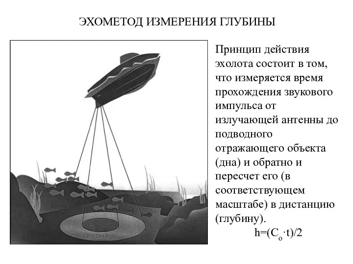 Эхометод измерения глубины
 Автомобили с управляемыми системами подрессоривания