- Assembly Document - Essentials

Содержание
- 2. Agenda Assembly End User vs API Assembly Structure Transient Geometry: using Matrices and Vectors Proxies Constraints
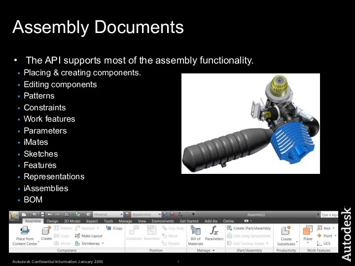
- 3. Assembly Documents The API supports most of the assembly functionality. Placing & creating components. Editing components
- 4. Assembly Document as an End User
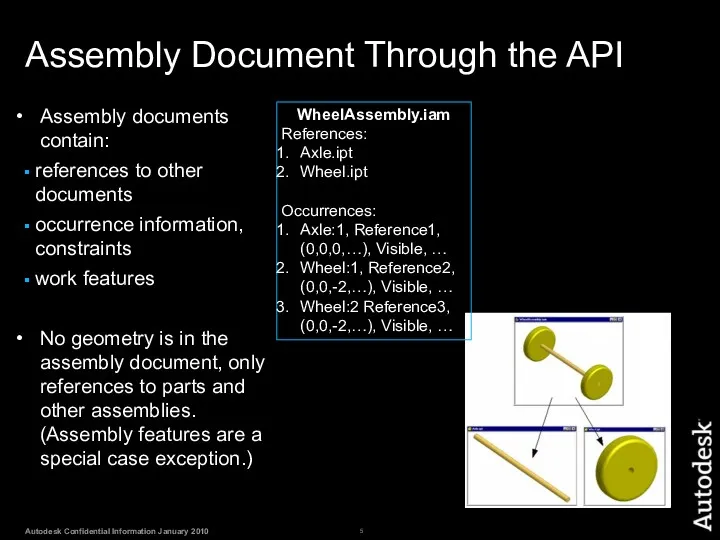
- 5. Assembly Document Through the API Assembly documents contain: references to other documents occurrence information, constraints work
- 6. Assembly Document Structure API The ComponentOccurrences object is accessed through the Occurrences property and allows iteration
- 7. Assembly Structure Traversal
- 8. Assembly Structure Traversal - Example Public Sub AssemblyTraversal() ' Get the active document, assuming it's an
- 9. Creating Occurrences Add( FileName As String, Position As Matrix ) As ComponentOccurrence AddByComponentDefinition( CompDef As ComponentDefinition,
- 10. Creating an Occurrence - Example Public Sub AddFromFile() Dim oDoc As AssemblyDocument oDoc = _InvApplication.ActiveDocument Dim
- 11. Creating Occurrences With Options AddWithOptions(FullDocumentName As String, Position As Matrix, _ Options As NameValueMap) As ComponentOccurrence
- 12. Add With Options - Example 'Create a new NameValueMap object Dim oOptions As NameValueMap oOptions =
- 13. Transient Geometry Math Objects The TransientGeometry object allows you to create some mathematical objects that can
- 14. What is a Matrix? A matrix is a rectangular array of numbers. A 3-D matrix is
- 15. A Matrix in Inventor In computer graphics a matrix is commonly used to: Define a coordinate
- 16. Matrix and Occurrences When placing an occurrence the matrix defines the position of the part within
- 17. Matrix as a Transform A matrix can be used to define a transformation for an existing
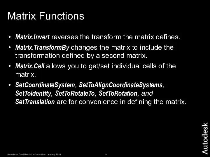
- 18. Matrix Functions Matrix.Invert reverses the transform the matrix defines. Matrix.TransformBy changes the matrix to include the
- 19. Vectors Vectors define a direction and magnitude. A Vector can be used to define the movement
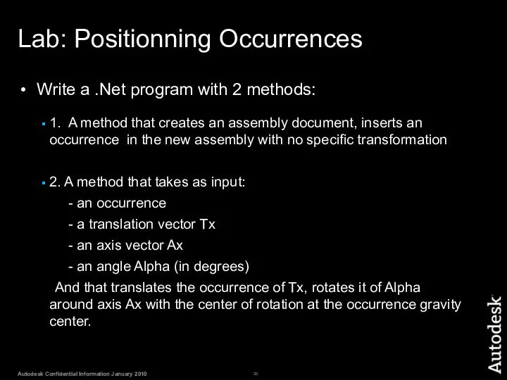
- 20. Lab: Positionning Occurrences Write a .Net program with 2 methods: 1. A method that creates an
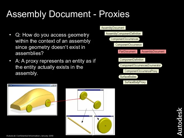
- 21. Assembly Document - Proxies Q: How do you access geometry within the context of an assembly
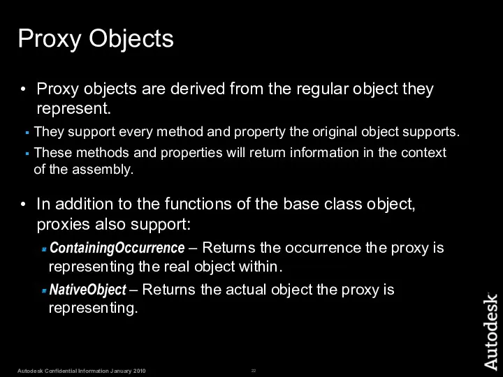
- 22. Proxy Objects Proxy objects are derived from the regular object they represent. They support every method
- 23. Proxy Objects Proxies define a path to the actual object. Cylindrical Face 1 Wheel:1\CylinderFace Cylindrical Face
- 24. Creating Proxies - Example Public Sub CreateProxy() Dim oAsmDef As AssemblyComponentDefinition oAsmDef = _InvApplication.ActiveDocument.ComponentDefinition Dim oOcc1
- 25. Assembly Document – Constraints Constraint creation can take as input work geometry from the assembly or
- 26. Adding Constraints – from native objects Public Sub MateConstraintOfWorkPlanes() Dim oAsmCompDef As AssemblyComponentDefinition oAsmCompDef = ThisApplication.ActiveDocument.ComponentDefinition
- 27. Adding Constraints – from proxy objects Public Sub MateConstraintWithLimits() ' Set a reference to the assembly
- 28. Lab: Creation of constraints Manually (not with the API), create a simple bolt part like the
- 30. Скачать презентацию
Agenda
Assembly End User vs API
Assembly Structure
Transient Geometry:
Agenda
Assembly End User vs API
Assembly Structure
Transient Geometry:
Assembly Documents
The API supports most of the assembly functionality.
Placing & creating
Assembly Documents
The API supports most of the assembly functionality.
Placing & creating
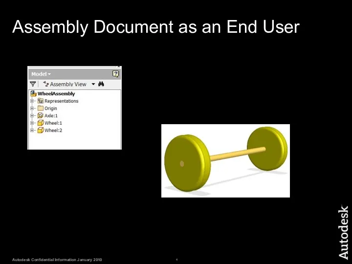
Assembly Document as an End User
Assembly Document as an End User
Assembly Document Through the API
Assembly documents contain:
references to other documents
occurrence information,
Assembly Document Through the API
Assembly documents contain:
references to other documents
occurrence information,
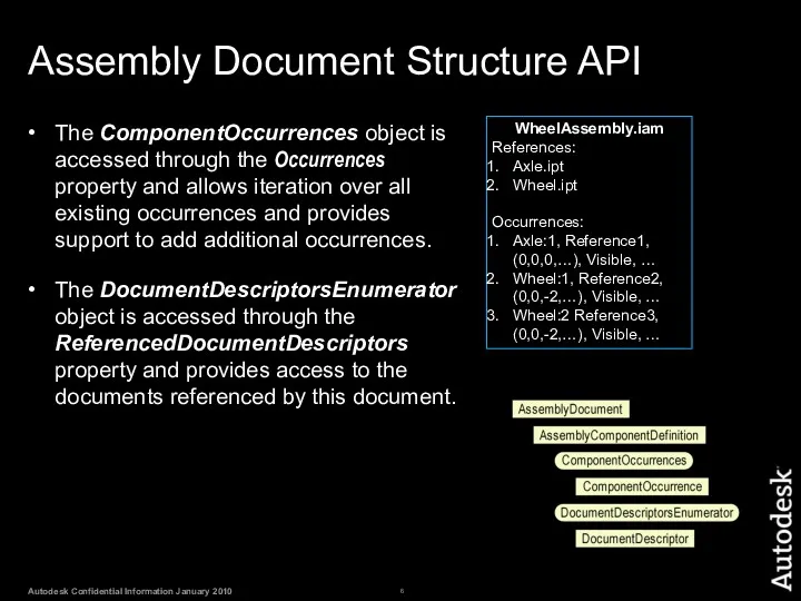
Assembly Document Structure API
The ComponentOccurrences object is accessed through the Occurrences
Assembly Document Structure API
The ComponentOccurrences object is accessed through the Occurrences
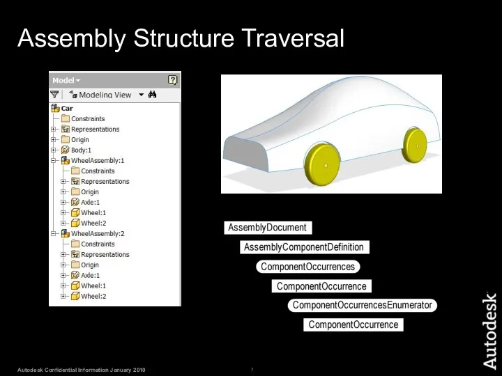
Assembly Structure Traversal
Assembly Structure Traversal
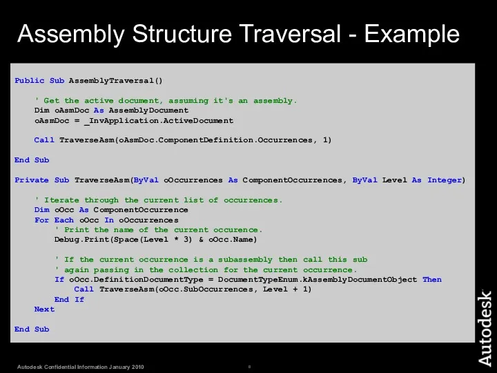
Assembly Structure Traversal - Example
Public Sub AssemblyTraversal()
' Get the active
Assembly Structure Traversal - Example
Public Sub AssemblyTraversal()
' Get the active
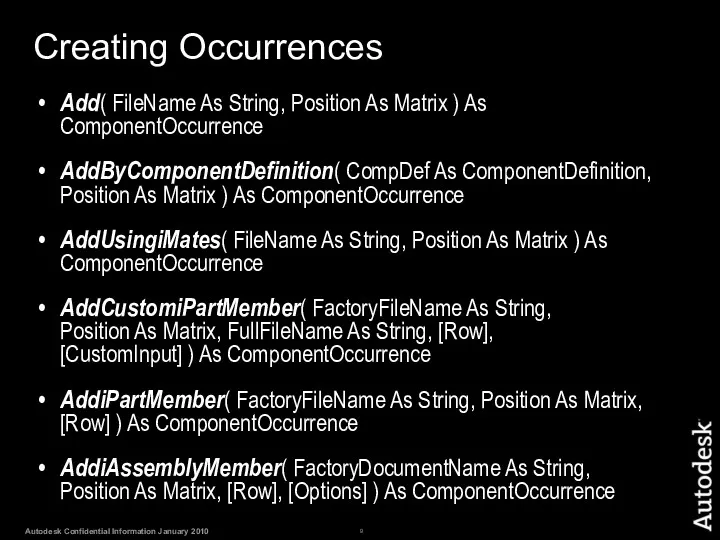
Creating Occurrences
Add( FileName As String, Position As Matrix ) As ComponentOccurrence
AddByComponentDefinition(
Creating Occurrences
Add( FileName As String, Position As Matrix ) As ComponentOccurrence
AddByComponentDefinition(
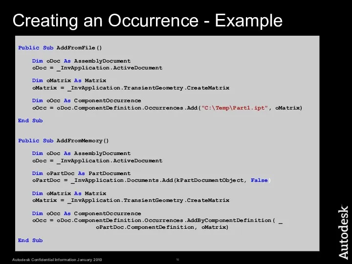
Creating an Occurrence - Example
Public Sub AddFromFile()
Dim oDoc As AssemblyDocument
Creating an Occurrence - Example
Public Sub AddFromFile()
Dim oDoc As AssemblyDocument
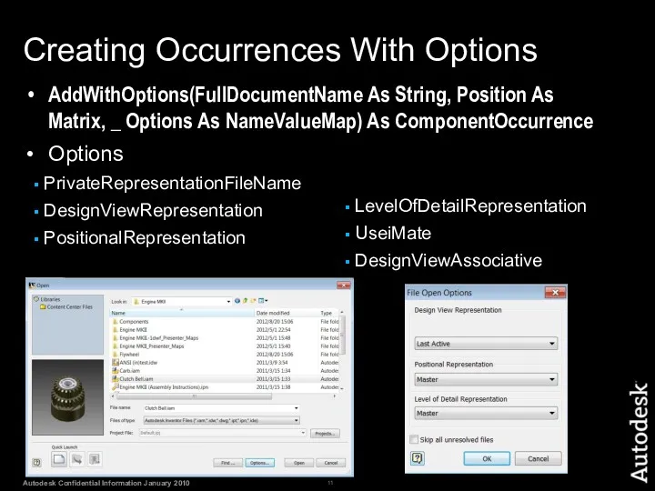
Creating Occurrences With Options
AddWithOptions(FullDocumentName As String, Position As Matrix, _ Options
Creating Occurrences With Options
AddWithOptions(FullDocumentName As String, Position As Matrix, _ Options
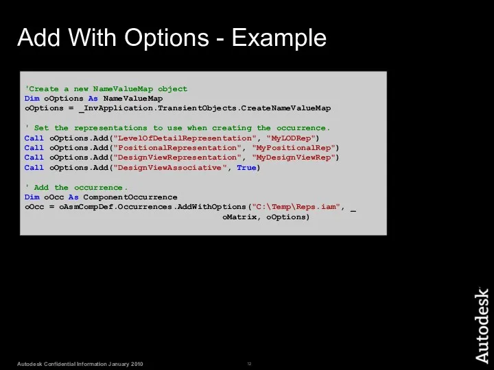
Add With Options - Example
'Create a new NameValueMap object
Dim oOptions As
Add With Options - Example
'Create a new NameValueMap object
Dim oOptions As
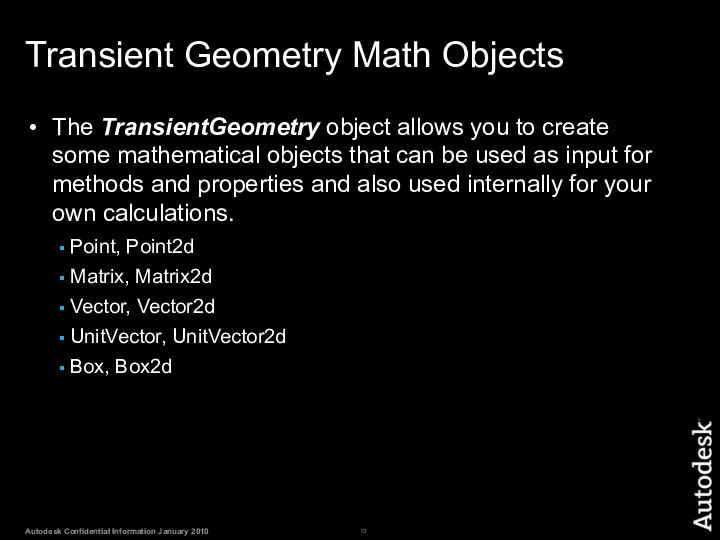
Transient Geometry Math Objects
The TransientGeometry object allows you to create some
Transient Geometry Math Objects
The TransientGeometry object allows you to create some
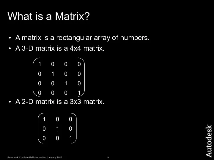
What is a Matrix?
A matrix is a rectangular array of numbers.
A
What is a Matrix?
A matrix is a rectangular array of numbers.
A
A Matrix in Inventor
In computer graphics a matrix is commonly used
A Matrix in Inventor
In computer graphics a matrix is commonly used
Matrix and Occurrences
When placing an occurrence the matrix defines the position
Matrix and Occurrences
When placing an occurrence the matrix defines the position
Matrix as a Transform
A matrix can be used to define a
Matrix as a Transform
A matrix can be used to define a
Matrix Functions
Matrix.Invert reverses the transform the matrix defines.
Matrix.TransformBy changes the matrix
Matrix Functions
Matrix.Invert reverses the transform the matrix defines.
Matrix.TransformBy changes the matrix

Vectors
Vectors define a direction and magnitude.
A Vector can be used to
Vectors
Vectors define a direction and magnitude.
A Vector can be used to
Lab: Positionning Occurrences
Write a .Net program with 2 methods:
1. A method
Lab: Positionning Occurrences
Write a .Net program with 2 methods:
1. A method
Assembly Document - Proxies
Q: How do you access geometry within the
Assembly Document - Proxies
Q: How do you access geometry within the
Proxy Objects
Proxy objects are derived from the regular object they represent.
They
Proxy Objects
Proxy objects are derived from the regular object they represent.
They
Proxy Objects
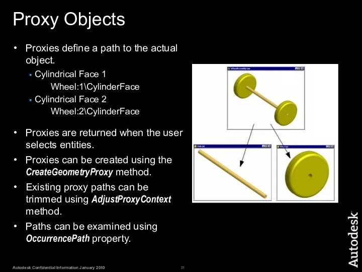
Proxies define a path to the actual object.
Cylindrical Face 1
Wheel:1\CylinderFace
Cylindrical
Proxy Objects
Proxies define a path to the actual object.
Cylindrical Face 1
Wheel:1\CylinderFace
Cylindrical
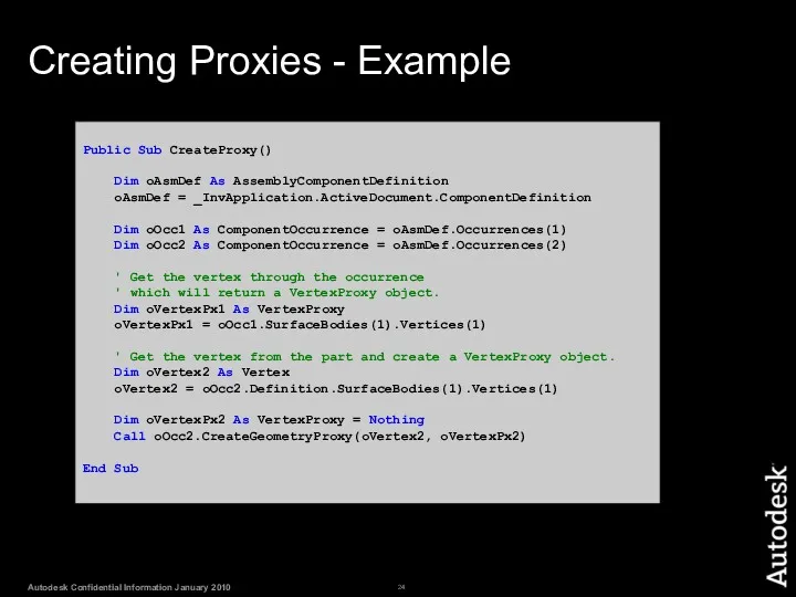
Creating Proxies - Example
Public Sub CreateProxy()
Dim oAsmDef As AssemblyComponentDefinition
oAsmDef
Creating Proxies - Example
Public Sub CreateProxy()
Dim oAsmDef As AssemblyComponentDefinition
oAsmDef
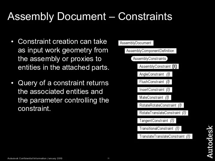
Assembly Document – Constraints
Constraint creation can take as input work geometry
Assembly Document – Constraints
Constraint creation can take as input work geometry
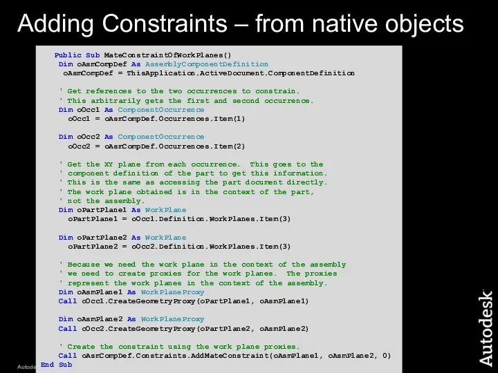
Adding Constraints – from native objects
Public Sub MateConstraintOfWorkPlanes()
Dim oAsmCompDef
Adding Constraints – from native objects
Public Sub MateConstraintOfWorkPlanes()
Dim oAsmCompDef
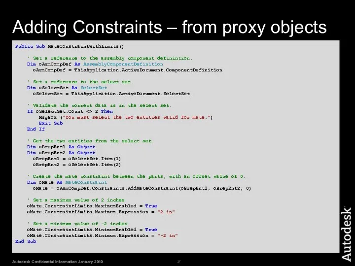
Adding Constraints – from proxy objects
Public Sub MateConstraintWithLimits()
' Set a reference
Adding Constraints – from proxy objects
Public Sub MateConstraintWithLimits()
' Set a reference
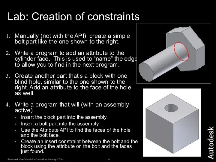
Lab: Creation of constraints
Manually (not with the API), create a simple
Lab: Creation of constraints
Manually (not with the API), create a simple
 Учебное пособие Векторный редактор Inscape
 Правовые нормы, относящиеся к информации, правонарушения в информационной сфере, меры их предупреждения
 Журналистика данных
 Информация, ее виды и свойства. 7 класс
 Practical work №9. Internet Technology
 Своя игра. Викторина. Шаблон
 Сведения о компьютере
 Безопасность ребенка в сети
 БИТ.CRM 3. Удобный инструмент для контроля и анализа взаимодействий с клиентом
 Дыбыстық ақпаратты өңдеу. Дыбыс жазу. Информатика сабағы 3 сынып
 Сортировки. Программирование. Семинар 4
 Достоверность информации в Интернете
 Основы применения методов системного анализа в проектировании информационных систем и формализации фармацевтической информации
 Електронна пошта
 Построение графиков в табличном процессоре. 9 класс
 Презентация Работа с файлами в Паскале
 Графічний редактор (векторний, расторний)
 Вступ до С. Перша проста програма
 Клавиатура. Виды клавиатуры
 Функциональное и доменное тестирование
 Актуальные проблемы НИР в области образования и информационных технологий
 Руководство пользователя. Мобильное приложение: мобильный инженер. ООО Ресурс Концепт
 Введение в Windows Forms
 Информационные жанры
 Портал с базой данных специалистов различных направлений по городам Казахстана
 Структура веб-сайтів. Етапи створення веб-сайтів
 Методы тестирования
 Основные понятия в тестировании. Тестовые артефакты