- Basic device configuration switching, routing and wireless

Содержание
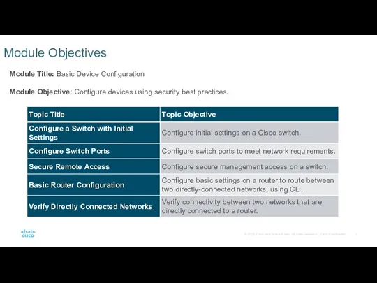
- 2. Module Objectives Module Title: Basic Device Configuration Module Objective: Configure devices using security best practices.
- 3. 1.1 Configure a Switch with Initial Settings
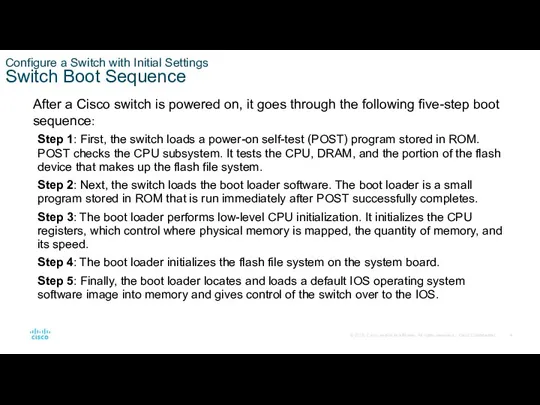
- 4. Configure a Switch with Initial Settings Switch Boot Sequence After a Cisco switch is powered on,
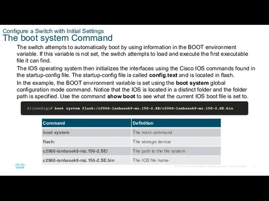
- 5. Configure a Switch with Initial Settings The boot system Command The switch attempts to automatically boot
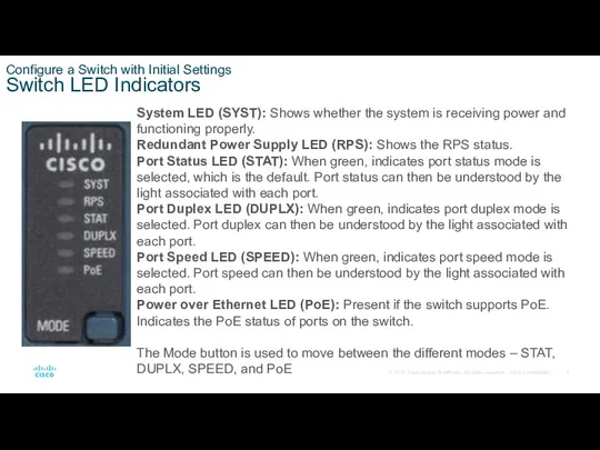
- 6. Configure a Switch with Initial Settings Switch LED Indicators System LED (SYST): Shows whether the system
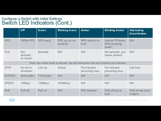
- 7. Configure a Switch with Initial Settings Switch LED Indicators (Cont.)
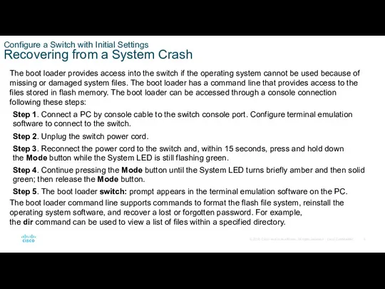
- 8. Configure a Switch with Initial Settings Recovering from a System Crash The boot loader provides access
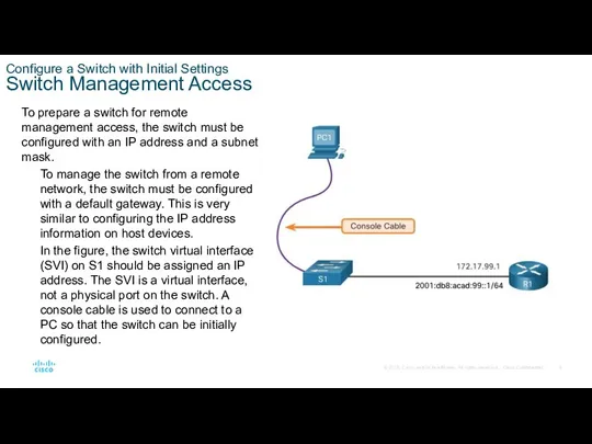
- 9. Configure a Switch with Initial Settings Switch Management Access To prepare a switch for remote management
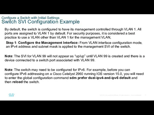
- 10. Configure a Switch with Initial Settings Switch SVI Configuration Example By default, the switch is configured
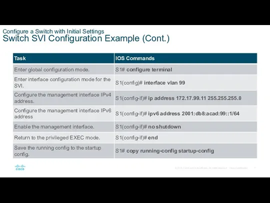
- 11. Configure a Switch with Initial Settings Switch SVI Configuration Example (Cont.)
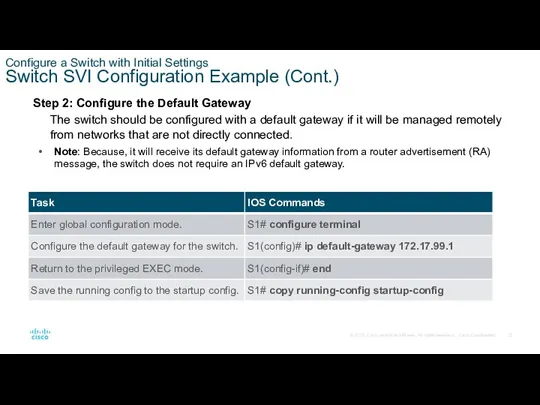
- 12. Configure a Switch with Initial Settings Switch SVI Configuration Example (Cont.) Step 2: Configure the Default
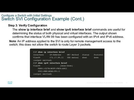
- 13. Configure a Switch with Initial Settings Switch SVI Configuration Example (Cont.) Step 3: Verify Configuration The
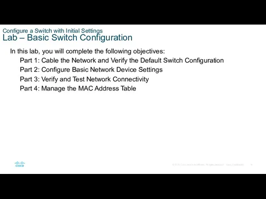
- 14. Configure a Switch with Initial Settings Lab – Basic Switch Configuration In this lab, you will
- 15. 1.2 Configure Switch Ports
- 16. Configure Switch Ports Duplex Communication Full-duplex communication increases bandwidth efficiency by allowing both ends of a
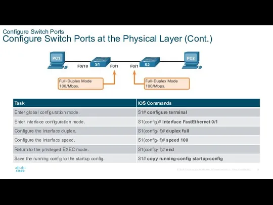
- 17. Configure Switch Ports Configure Switch Ports at the Physical Layer Switch ports can be manually configured
- 18. Configure Switch Ports Configure Switch Ports at the Physical Layer (Cont.)
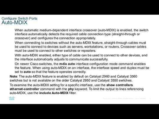
- 19. Configure Switch Ports Auto-MDIX When automatic medium-dependent interface crossover (auto-MDIX) is enabled, the switch interface automatically
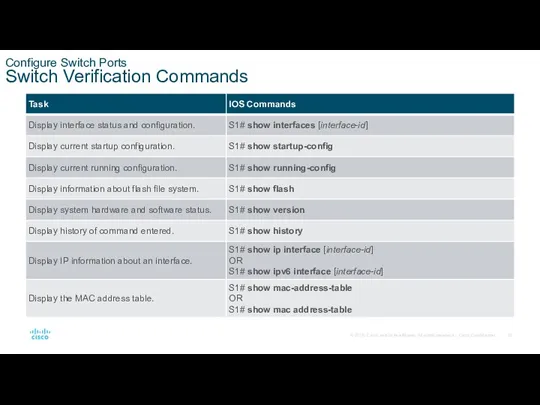
- 20. Configure Switch Ports Switch Verification Commands
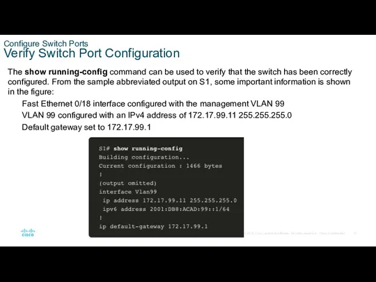
- 21. Configure Switch Ports Verify Switch Port Configuration The show running-config command can be used to verify
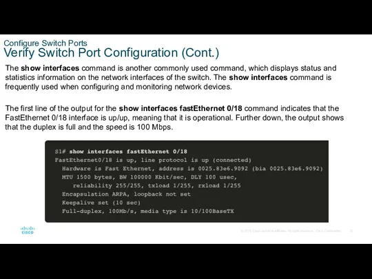
- 22. Configure Switch Ports Verify Switch Port Configuration (Cont.) The show interfaces command is another commonly used
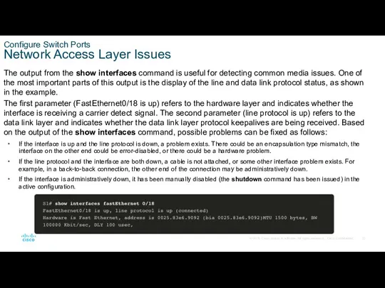
- 23. Configure Switch Ports Network Access Layer Issues The output from the show interfaces command is useful
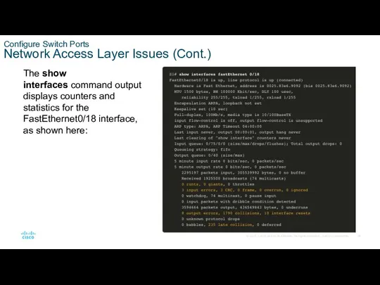
- 24. Configure Switch Ports Network Access Layer Issues (Cont.) The show interfaces command output displays counters and
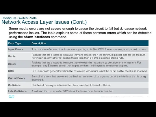
- 25. Configure Switch Ports Network Access Layer Issues (Cont.) Some media errors are not severe enough to
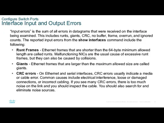
- 26. Configure Switch Ports Interface Input and Output Errors “Input errors” is the sum of all errors
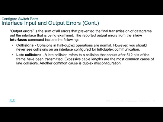
- 27. Configure Switch Ports Interface Input and Output Errors (Cont.) “Output errors” is the sum of all
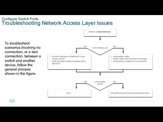
- 28. Configure Switch Ports Troubleshooting Network Access Layer Issues To troubleshoot scenarios involving no connection, or a
- 29. 1.3 Secure Remote Access
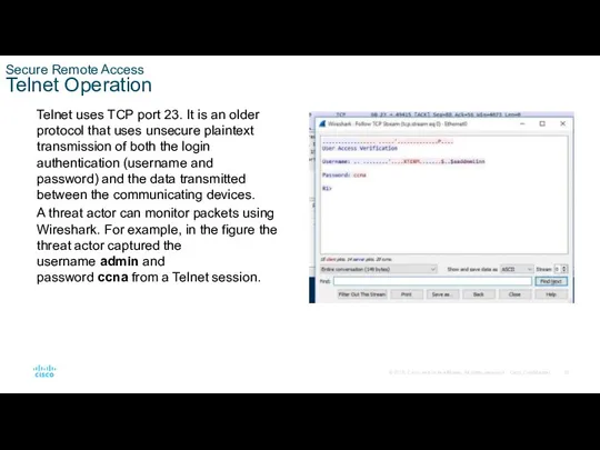
- 30. Secure Remote Access Telnet Operation Telnet uses TCP port 23. It is an older protocol that
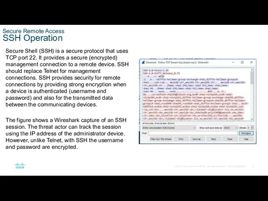
- 31. Secure Remote Access SSH Operation Secure Shell (SSH) is a secure protocol that uses TCP port
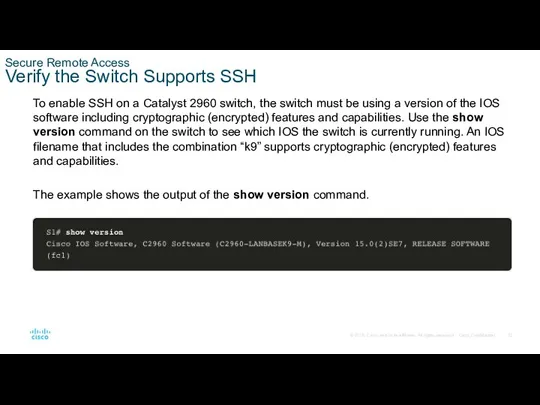
- 32. Secure Remote Access Verify the Switch Supports SSH To enable SSH on a Catalyst 2960 switch,
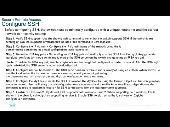
- 33. Secure Remote Access Configure SSH Before configuring SSH, the switch must be minimally configured with a
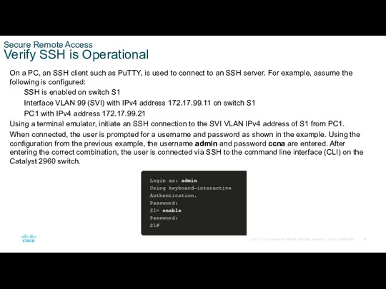
- 34. Secure Remote Access Verify SSH is Operational On a PC, an SSH client such as PuTTY,
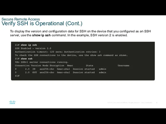
- 35. Secure Remote Access Verify SSH is Operational (Cont.) To display the version and configuration data for
- 36. Secure Remote Access Packet Tracer – Configure SSH In this Packet Tracer, you will do the
- 37. 1.4 Basic Router Configuration
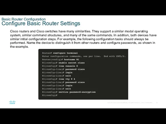
- 38. Basic Router Configuration Configure Basic Router Settings Cisco routers and Cisco switches have many similarities. They
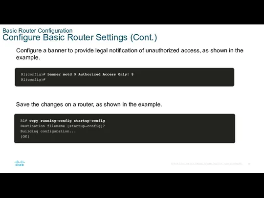
- 39. Basic Router Configuration Configure Basic Router Settings (Cont.) Configure a banner to provide legal notification of
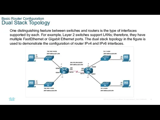
- 40. Basic Router Configuration Dual Stack Topology One distinguishing feature between switches and routers is the type
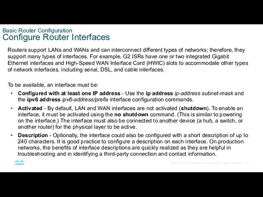
- 41. Basic Router Configuration Configure Router Interfaces Routers support LANs and WANs and can interconnect different types
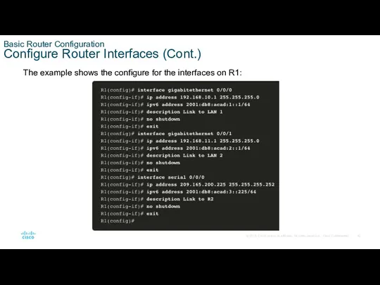
- 42. Basic Router Configuration Configure Router Interfaces (Cont.) The example shows the configure for the interfaces on
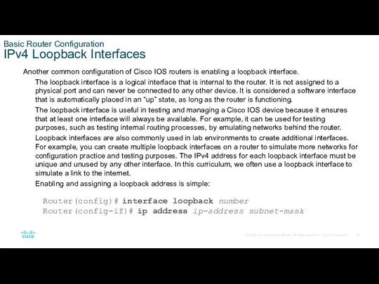
- 43. Basic Router Configuration IPv4 Loopback Interfaces Another common configuration of Cisco IOS routers is enabling a
- 44. Basic Router Configuration Packet Tracer – Configure Router Interfaces In this Packet Tracer activity, you will
- 45. 1.5 Verify Directly Connected Networks
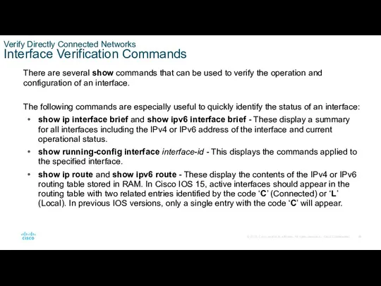
- 46. Verify Directly Connected Networks Interface Verification Commands There are several show commands that can be used
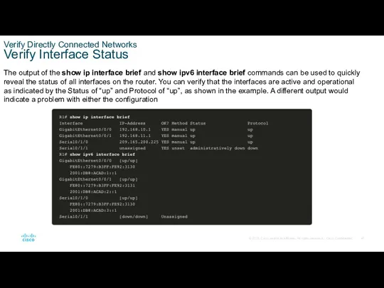
- 47. Verify Directly Connected Networks Verify Interface Status The output of the show ip interface brief and
- 48. Verify Directly Connected Networks Verify IPv6 Link Local and Multicast Addresses The output of the show
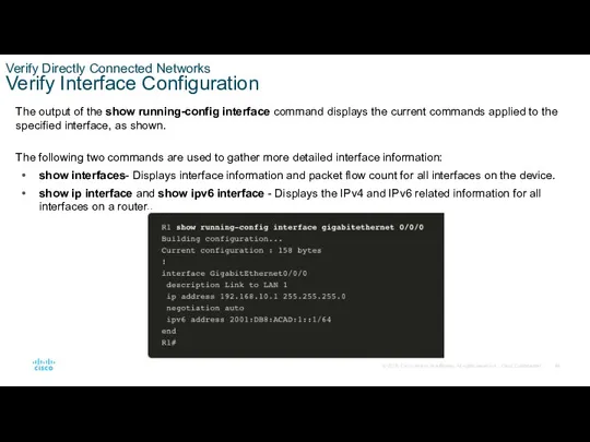
- 49. Verify Directly Connected Networks Verify Interface Configuration The output of the show running-config interface command displays
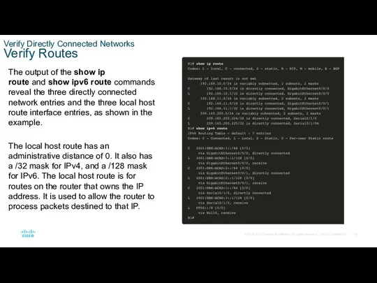
- 50. Verify Directly Connected Networks Verify Routes The output of the show ip route and show ipv6
- 51. Verify Directly Connected Networks Verify Routes (Cont.) A ‘C’ next to a route within the routing
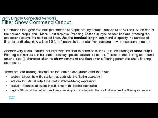
- 52. Verify Directly Connected Networks Filter Show Command Output Commands that generate multiple screens of output are,
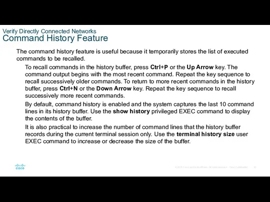
- 53. Verify Directly Connected Networks Command History Feature The command history feature is useful because it temporarily
- 54. Verify Directly Connected Networks Packet Tracer – Verify Directly Connected Networks In this Packet Tracer activity,
- 55. 1.6 Module Practice and Quiz
- 56. Module Practice and Quiz Packet Tracer – Implement a Small Network In this Packet Tracer activity,
- 58. Скачать презентацию
Module Objectives
Module Title: Basic Device Configuration
Module Objective: Configure devices using security
Module Objectives
Module Title: Basic Device Configuration
Module Objective: Configure devices using security
1.1 Configure a Switch with Initial Settings
1.1 Configure a Switch with Initial Settings
Configure a Switch with Initial Settings
Switch Boot Sequence
After a Cisco switch
Configure a Switch with Initial Settings
Switch Boot Sequence
After a Cisco switch
Configure a Switch with Initial Settings
The boot system Command
The switch attempts
Configure a Switch with Initial Settings
The boot system Command
The switch attempts
Configure a Switch with Initial Settings
Switch LED Indicators
System LED (SYST): Shows
Configure a Switch with Initial Settings
Switch LED Indicators
System LED (SYST): Shows
Configure a Switch with Initial Settings
Switch LED Indicators (Cont.)
Configure a Switch with Initial Settings
Switch LED Indicators (Cont.)
Configure a Switch with Initial Settings
Recovering from a System Crash
The boot
Configure a Switch with Initial Settings
Recovering from a System Crash
The boot
Configure a Switch with Initial Settings
Switch Management Access
To prepare a switch
Configure a Switch with Initial Settings
Switch Management Access
To prepare a switch
Configure a Switch with Initial Settings
Switch SVI Configuration Example
By default, the
Configure a Switch with Initial Settings
Switch SVI Configuration Example
By default, the
Configure a Switch with Initial Settings
Switch SVI Configuration Example (Cont.)
Configure a Switch with Initial Settings
Switch SVI Configuration Example (Cont.)
Configure a Switch with Initial Settings
Switch SVI Configuration Example (Cont.)
Step 2:
Configure a Switch with Initial Settings
Switch SVI Configuration Example (Cont.)
Step 2:
Configure a Switch with Initial Settings
Switch SVI Configuration Example (Cont.)
Step 3:
Configure a Switch with Initial Settings
Switch SVI Configuration Example (Cont.)
Step 3:
Configure a Switch with Initial Settings
Lab – Basic Switch Configuration
In this
Configure a Switch with Initial Settings
Lab – Basic Switch Configuration
In this
1.2 Configure Switch Ports
1.2 Configure Switch Ports
Configure Switch Ports
Duplex Communication
Full-duplex communication increases bandwidth efficiency by allowing both
Configure Switch Ports
Duplex Communication
Full-duplex communication increases bandwidth efficiency by allowing both
Configure Switch Ports
Configure Switch Ports at the Physical Layer
Switch ports can
Configure Switch Ports
Configure Switch Ports at the Physical Layer
Switch ports can
Configure Switch Ports
Configure Switch Ports at the Physical Layer (Cont.)
Configure Switch Ports
Configure Switch Ports at the Physical Layer (Cont.)
Configure Switch Ports
Auto-MDIX
When automatic medium-dependent interface crossover (auto-MDIX) is enabled, the
Configure Switch Ports
Auto-MDIX
When automatic medium-dependent interface crossover (auto-MDIX) is enabled, the
Configure Switch Ports
Switch Verification Commands
Configure Switch Ports
Switch Verification Commands
Configure Switch Ports
Verify Switch Port Configuration
The show running-config command can be used to
Configure Switch Ports
Verify Switch Port Configuration
The show running-config command can be used to
Configure Switch Ports
Verify Switch Port Configuration (Cont.)
The show interfaces command is another commonly
Configure Switch Ports
Verify Switch Port Configuration (Cont.)
The show interfaces command is another commonly
Configure Switch Ports
Network Access Layer Issues
The output from the show interfaces command is
Configure Switch Ports
Network Access Layer Issues
The output from the show interfaces command is
Configure Switch Ports
Network Access Layer Issues (Cont.)
The show interfaces command output displays counters
Configure Switch Ports
Network Access Layer Issues (Cont.)
The show interfaces command output displays counters
Configure Switch Ports
Network Access Layer Issues (Cont.)
Some media errors are not
Configure Switch Ports
Network Access Layer Issues (Cont.)
Some media errors are not
Configure Switch Ports
Interface Input and Output Errors
“Input errors” is the sum
Configure Switch Ports
Interface Input and Output Errors
“Input errors” is the sum
Configure Switch Ports
Interface Input and Output Errors (Cont.)
“Output errors” is the
Configure Switch Ports
Interface Input and Output Errors (Cont.)
“Output errors” is the
Configure Switch Ports
Troubleshooting Network Access Layer Issues
To troubleshoot scenarios involving no
Configure Switch Ports
Troubleshooting Network Access Layer Issues
To troubleshoot scenarios involving no
1.3 Secure Remote Access
1.3 Secure Remote Access
Secure Remote Access
Telnet Operation
Telnet uses TCP port 23. It is an
Secure Remote Access
Telnet Operation
Telnet uses TCP port 23. It is an
Secure Remote Access
SSH Operation
Secure Shell (SSH) is a secure protocol that
Secure Remote Access
SSH Operation
Secure Shell (SSH) is a secure protocol that
Secure Remote Access
Verify the Switch Supports SSH
To enable SSH on a
Secure Remote Access
Verify the Switch Supports SSH
To enable SSH on a
Secure Remote Access
Configure SSH
Before configuring SSH, the switch must be minimally
Secure Remote Access
Configure SSH
Before configuring SSH, the switch must be minimally
Secure Remote Access
Verify SSH is Operational
On a PC, an SSH client
Secure Remote Access
Verify SSH is Operational
On a PC, an SSH client
Secure Remote Access
Verify SSH is Operational (Cont.)
To display the version and
Secure Remote Access
Verify SSH is Operational (Cont.)
To display the version and
Secure Remote Access
Packet Tracer – Configure SSH
In this Packet Tracer, you
Secure Remote Access
Packet Tracer – Configure SSH
In this Packet Tracer, you
1.4 Basic Router Configuration
1.4 Basic Router Configuration
Basic Router Configuration
Configure Basic Router Settings
Cisco routers and Cisco switches have
Basic Router Configuration
Configure Basic Router Settings
Cisco routers and Cisco switches have
Basic Router Configuration
Configure Basic Router Settings (Cont.)
Configure a banner to provide
Basic Router Configuration
Configure Basic Router Settings (Cont.)
Configure a banner to provide
Basic Router Configuration
Dual Stack Topology
One distinguishing feature between switches and routers
Basic Router Configuration
Dual Stack Topology
One distinguishing feature between switches and routers
Basic Router Configuration
Configure Router Interfaces
Routers support LANs and WANs and can
Basic Router Configuration
Configure Router Interfaces
Routers support LANs and WANs and can
Basic Router Configuration
Configure Router Interfaces (Cont.)
The example shows the configure for
Basic Router Configuration
Configure Router Interfaces (Cont.)
The example shows the configure for
Basic Router Configuration
IPv4 Loopback Interfaces
Another common configuration of Cisco IOS routers
Basic Router Configuration
IPv4 Loopback Interfaces
Another common configuration of Cisco IOS routers
Basic Router Configuration
Packet Tracer – Configure Router Interfaces
In this Packet Tracer
Basic Router Configuration
Packet Tracer – Configure Router Interfaces
In this Packet Tracer
1.5 Verify Directly Connected Networks
1.5 Verify Directly Connected Networks
Verify Directly Connected Networks
Interface Verification Commands
There are several show commands that can be
Verify Directly Connected Networks
Interface Verification Commands
There are several show commands that can be
Verify Directly Connected Networks
Verify Interface Status
The output of the show ip interface
Verify Directly Connected Networks
Verify Interface Status
The output of the show ip interface

Verify Directly Connected Networks
Verify IPv6 Link Local and Multicast Addresses
The output
Verify Directly Connected Networks
Verify IPv6 Link Local and Multicast Addresses
The output
Verify Directly Connected Networks
Verify Interface Configuration
The output of the show running-config interface command
Verify Directly Connected Networks
Verify Interface Configuration
The output of the show running-config interface command
Verify Directly Connected Networks
Verify Routes
The output of the show ip route and show ipv6
Verify Directly Connected Networks
Verify Routes
The output of the show ip route and show ipv6

Verify Directly Connected Networks
Verify Routes (Cont.)
A ‘C’ next to a route
Verify Directly Connected Networks
Verify Routes (Cont.)
A ‘C’ next to a route
Verify Directly Connected Networks
Filter Show Command Output
Commands that generate multiple screens
Verify Directly Connected Networks
Filter Show Command Output
Commands that generate multiple screens
Verify Directly Connected Networks
Command History Feature
The command history feature is useful
Verify Directly Connected Networks
Command History Feature
The command history feature is useful
Verify Directly Connected Networks
Packet Tracer – Verify Directly Connected Networks
In this
Verify Directly Connected Networks
Packet Tracer – Verify Directly Connected Networks
In this
1.6 Module Practice and Quiz
1.6 Module Practice and Quiz
Module Practice and Quiz
Packet Tracer – Implement a Small Network
In this
Module Practice and Quiz
Packet Tracer – Implement a Small Network
In this
 Программное обеспечение ПК
 Модификация базы данных студенты
 Open Cascade VPN. Installation and activation manual
 CSS basics
 Электронные таблицы Excel 2007. Средства анализа данных
 Школа блогеров (инструкция)
 Игра. Условное представление.часть1
 Значение коммуникации в управлении организацией
 Устройство компьютера. История развития вычислительной техники
 Безопасность персональных данных в сети Интернет
 Организация циклов на языке Pascal
 Применение информационных технологий для научных исследований в области земельного, природоресурсного, аграрного права
 Автоматизация процессного управления
 Компания Century Star Media Co
 Оформление цитат, списка литературы, библиографических ссылок
 Графічні об’єкти в текстовому документі
 Лабораторные работы
 Как устроена книга
 Конфигурация Весовая ред. 3.0 на платформе 1С: Предприятие 8.3
 Право и этика СМИ
 Использование интернет-банкинга
 Текстовые документы и технологии их создания. Обработка текстовой информации. Информатика и ИКТ. 8 класс
 Обработка рисунков и фотографий Adobe Photoshop. Создание презентации PowerPoint
 Аутсорсинг логистики электронной торговли
 IP-адрес
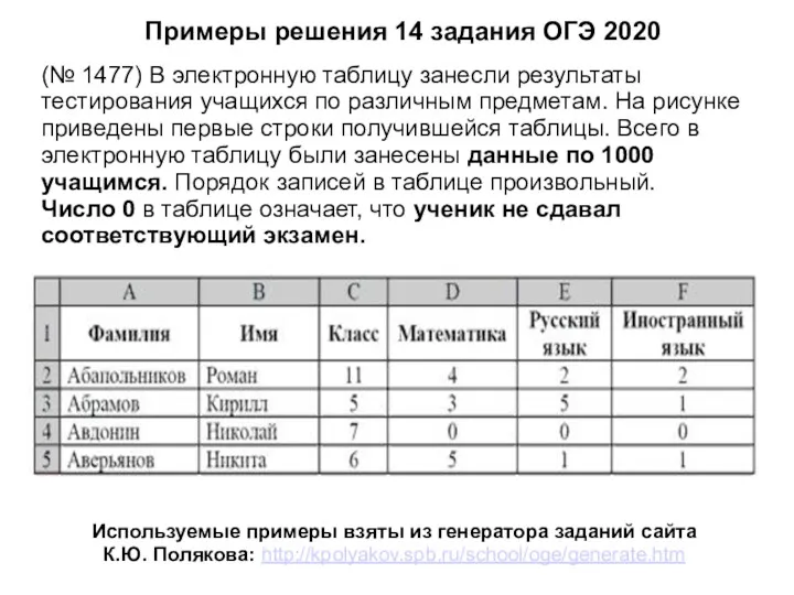 Примеры решения задания 14, ОГЭ по информатике
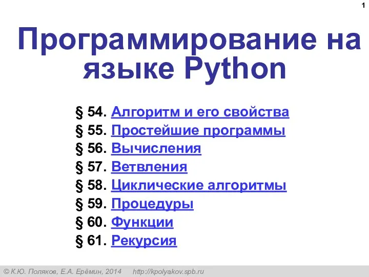 Алгоритм и его свойства
 Технические каналы утечки акустической информации