- Computer Science 686 Spring 2007. Intel EM64T and VT Extensions

Содержание
- 2. Recent CPU advances Intel Corporation’s newest CPUs for the Personal Computer market offer a 64-bit architecture
- 3. Our course’s purpose We want to study these new capabilities, how to activate them and how
- 4. Alternate access mechanism We will need to employ a different scheme for receiving output (or transmitting
- 5. Our remote-access scheme rackmount PC system gateway-server student workstation KVM cable ethernet cables ‘anchor00’ ‘anchor01’ ‘anchor02’
- 6. Universal Asynchronous Receiver-Transmitter (UART) See our CS686 course website at: for links to the UART manufacturer’s
- 7. Kudlick Classroom 08 09 10 15 16 17 18 19 20 28 29 30 04 05
- 8. PC-to-PC communications rackmount PC system student workstation KVM cable rackmount PC system student workstation KVM cable
- 9. Tx and Rx The UART has a transmission engine, and also a reception engine (they can
- 10. Serial data-transmission 0 1 1 0 0 0 0 1 The Transmitter Holding Register (8-bits) 0
- 11. Serial data reception clock input voltage clock-pulses trigger voltage-sampling and bit-shifts at regular intervals 0 1
- 12. DCE and DTE Original purpose of the UART was for PCs to communicate via the telephone
- 13. PC with a modem computer terminal modem serial cable phone wire Data Terminal Equipment (DTE) Data
- 14. Normal 9-wire serial cable 1 5 6 9 1 6 9 Carrier Detect Rx data Tx
- 15. Signal functions CD: Carrier Detect The modem asserts this signal to indicate that it successfully made
- 16. Signal functions (continued) RTS: Request To Send PC is ready for the modem to relay some
- 17. 9-wire null-modem cable CD RxD TxD GND DSR DTR RTS CTS RI CD RxD TxD GND
- 18. The 16550 UART registers Transmit Data Register Received Data Register Interrupt Enable Register Interrupt Identification Register
- 19. Rate of data-transfer The standard UART clock-frequency for PCs equals 1,843,200 cycles-per-second Each data-bit consumes 16
- 20. Divisor Latch The ‘Divisor Latch’ may be used to slow down the UART’s rate of data-transfer
- 21. How timing works Transmitter clock (bit-rate times 16) DATA OUT start-bit data-bit 0 data-bit 1 …
- 22. Programming interface RxD/TxD IER IIR/FCR LCR MCR LSR MSR SCR The PC uses eight consecutive I/O-ports
- 23. Modem Control Register 0 0 0 LOOP BACK OUT2 OUT1 RTS DTR 7 6 5 4
- 24. Modem Status Register DCD RI DSR CTS delta DCD delta RI delta DSR delta CTS 7
- 25. Line Status Register Error in Rx FIFO Transmitter idle THR empty Break interrupt Framing error Parity
- 26. Line Control Register Divisor Latch access set break stick parity even parity select parity enable number
- 27. Interrupt Enable Register 0 0 0 0 Modem Status change Rx Line Status change THR is
- 28. FIFO Control Register RCVR FIFO trigger-level reserved reserved DMA Mode select XMIT FIFO reset RCVR FIFO
- 29. Interrupt Identification Register 0 0 7 6 5 4 3 2 1 0 00 = FIFO-mode
- 30. Responding to interrupts You need to ‘clear’ a reported interrupt by taking some action -- depending
- 31. Usage flexibility A UART can be programmed to operate in “polled” mode or in “interrupt-driven” mode
- 32. How to transmit a byte Read the Line Status Register Write byte to the Transmitter Data
- 33. How to receive a byte Read the Line Status Register Read byte from the Receiver Data
- 34. How to implement in C/C++ // declare the program’s variables and constants char inch, outch =
- 35. How to initialize ‘loopback’ mode Set the Divisor Latch Access Bit in the Line Control Register
- 36. How to adjust the cpu’s IOPL Linux provides a system-call (to privileged programs) that need to
- 37. In-class exercise 1 Modify the ‘testuart.cpp’ demo-program by commenting out the instruction that places the UART
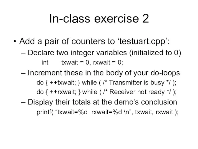
- 38. In-class exercise 2 Add a pair of counters to ‘testuart.cpp’: Declare two integer variables (initialized to
- 40. Скачать презентацию
Recent CPU advances
Intel Corporation’s newest CPUs for the Personal Computer market
Recent CPU advances
Intel Corporation’s newest CPUs for the Personal Computer market
Our course’s purpose
We want to study these new capabilities, how to
Our course’s purpose
We want to study these new capabilities, how to
Alternate access mechanism
We will need to employ a different scheme for
Alternate access mechanism
We will need to employ a different scheme for
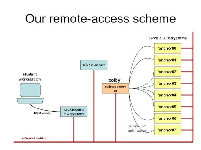
Our remote-access scheme
rackmount
PC system
gateway-server
student
workstation
KVM cable
ethernet cables
‘anchor00’
‘anchor01’
‘anchor02’
‘anchor03’
‘anchor04’
‘anchor05’
‘anchor06’
‘anchor07’
Core 2 Duo systems
‘colby’
CS
Our remote-access scheme
rackmount
PC system
gateway-server
student
workstation
KVM cable
ethernet cables
‘anchor00’
‘anchor01’
‘anchor02’
‘anchor03’
‘anchor04’
‘anchor05’
‘anchor06’
‘anchor07’
Core 2 Duo systems
‘colby’
CS
Universal Asynchronous Receiver-Transmitter
(UART)
See our CS686 course website at:
for links
Universal Asynchronous Receiver-Transmitter
(UART)
See our CS686 course website at:
for links
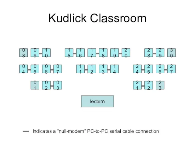
Kudlick Classroom
08
09
10
15
16
17
18
19
20
28
29
30
04
05
06
07
11
12
13
14
24
25
26
27
01
02
03
21
22
23
Indicates a “null-modem” PC-to-PC serial cable connection
lectern
Kudlick Classroom
08
09
10
15
16
17
18
19
20
28
29
30
04
05
06
07
11
12
13
14
24
25
26
27
01
02
03
21
22
23
Indicates a “null-modem” PC-to-PC serial cable connection
lectern
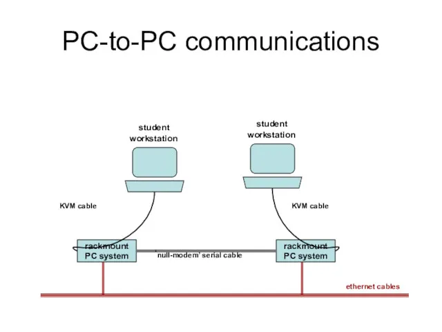
PC-to-PC communications
rackmount
PC system
student
workstation
KVM cable
rackmount
PC system
student
workstation
KVM cable
‘null-modem’ serial cable
ethernet
PC-to-PC communications
rackmount
PC system
student
workstation
KVM cable
rackmount
PC system
student
workstation
KVM cable
‘null-modem’ serial cable
ethernet
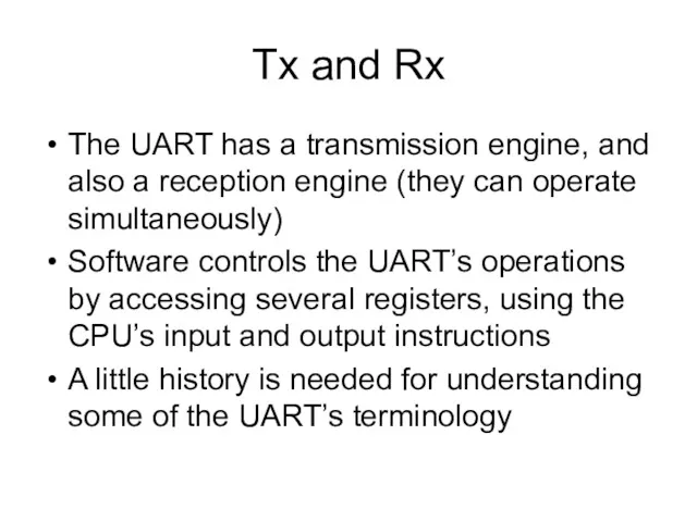
Tx and Rx
The UART has a transmission engine, and also a
Tx and Rx
The UART has a transmission engine, and also a
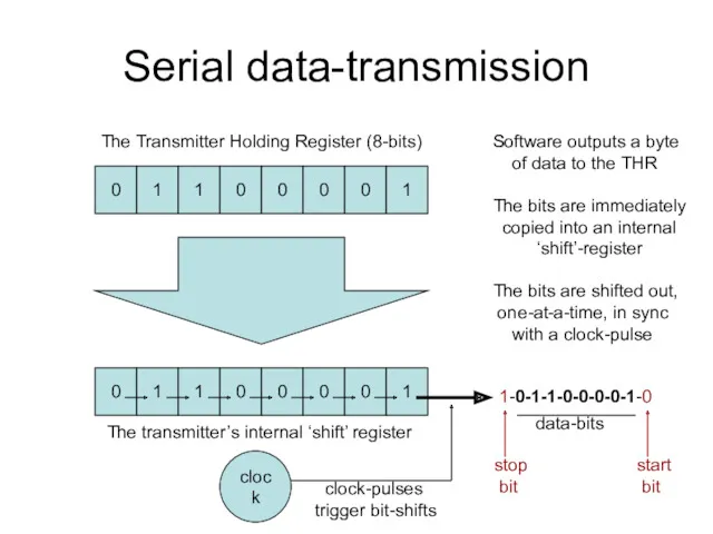
Serial data-transmission
0
1
1
0
0
0
0
1
The Transmitter Holding Register (8-bits)
0
1
1
0
0
0
0
1
The transmitter’s internal ‘shift’ register
clock
Software outputs
Serial data-transmission
0
1
1
0
0
0
0
1
The Transmitter Holding Register (8-bits)
0
1
1
0
0
0
0
1
The transmitter’s internal ‘shift’ register
clock
Software outputs
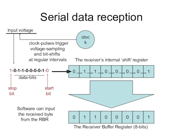
Serial data reception
clock
input voltage
clock-pulses trigger
voltage-sampling
and bit-shifts
at regular
Serial data reception
clock
input voltage
clock-pulses trigger
voltage-sampling
and bit-shifts
at regular
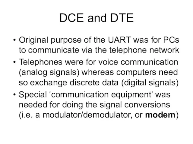
DCE and DTE
Original purpose of the UART was for PCs to
DCE and DTE
Original purpose of the UART was for PCs to
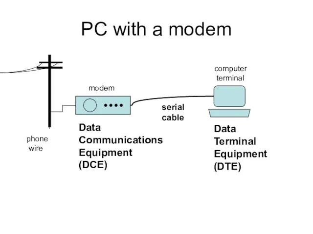
PC with a modem
computer
terminal
modem
serial
cable
phone
wire
Data
Terminal
Equipment
(DTE)
Data
Communications
Equipment
(DCE)
PC with a modem
computer
terminal
modem
serial
cable
phone
wire
Data
Terminal
Equipment
(DTE)
Data
Communications
Equipment
(DCE)
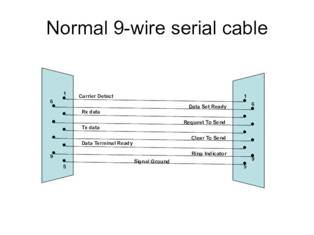
Normal 9-wire serial cable
1
5
6
9
1
6
9
Carrier Detect
Rx data
Tx data
Data Terminal Ready
Signal Ground
Data Set
Normal 9-wire serial cable
1
5
6
9
1
6
9
Carrier Detect
Rx data
Tx data
Data Terminal Ready
Signal Ground
Data Set
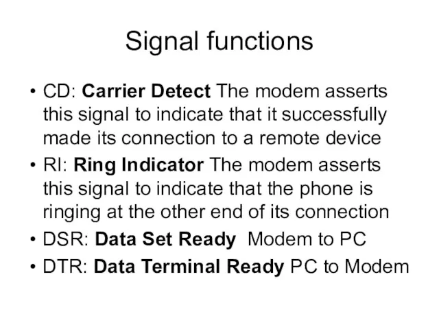
Signal functions
CD: Carrier Detect The modem asserts this signal to indicate
Signal functions
CD: Carrier Detect The modem asserts this signal to indicate
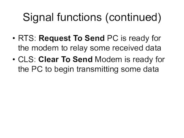
Signal functions (continued)
RTS: Request To Send PC is ready for the
Signal functions (continued)
RTS: Request To Send PC is ready for the
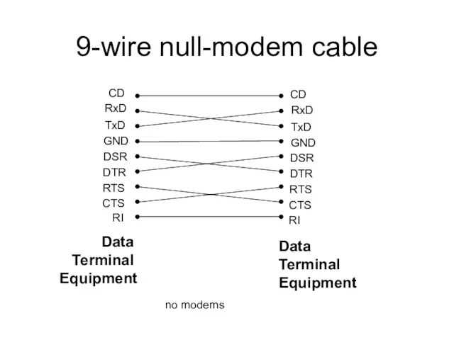
9-wire null-modem cable
CD
RxD
TxD
GND
DSR
DTR
RTS
CTS
RI
CD
RxD
TxD
GND
DSR
DTR
RTS
CTS
RI
Data
Terminal
Equipment
Data
Terminal
Equipment
no modems
9-wire null-modem cable
CD
RxD
TxD
GND
DSR
DTR
RTS
CTS
RI
CD
RxD
TxD
GND
DSR
DTR
RTS
CTS
RI
Data
Terminal
Equipment
Data
Terminal
Equipment
no modems
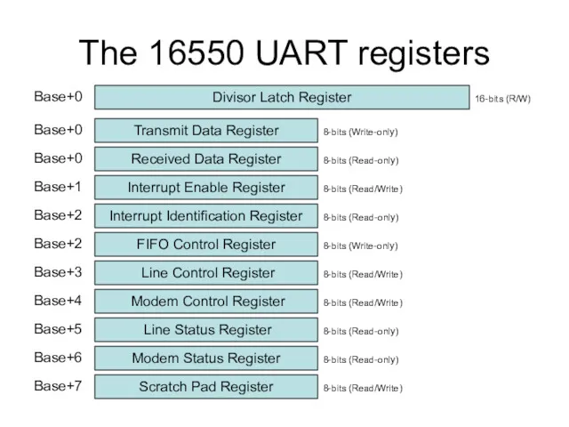
The 16550 UART registers
Transmit Data Register
Received Data Register
Interrupt Enable Register
Interrupt Identification
The 16550 UART registers
Transmit Data Register
Received Data Register
Interrupt Enable Register
Interrupt Identification
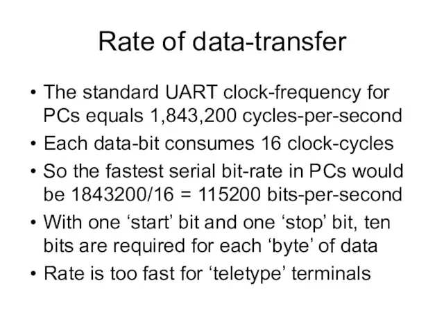
Rate of data-transfer
The standard UART clock-frequency for PCs equals 1,843,200 cycles-per-second
Each
Rate of data-transfer
The standard UART clock-frequency for PCs equals 1,843,200 cycles-per-second
Each
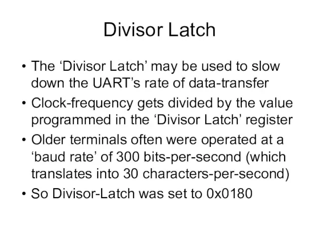
Divisor Latch
The ‘Divisor Latch’ may be used to slow down the
Divisor Latch
The ‘Divisor Latch’ may be used to slow down the
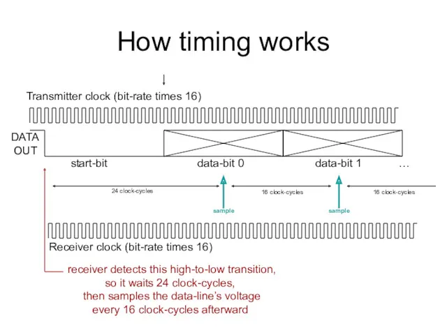
How timing works
Transmitter clock (bit-rate times 16)
DATA
OUT
start-bit data-bit 0 data-bit
How timing works
Transmitter clock (bit-rate times 16)
DATA
OUT
start-bit data-bit 0 data-bit
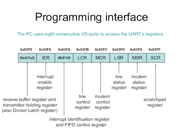
Programming interface
RxD/TxD
IER
IIR/FCR
LCR
MCR
LSR
MSR
SCR
The PC uses eight consecutive I/O-ports to access the UART’s
Programming interface
RxD/TxD
IER
IIR/FCR
LCR
MCR
LSR
MSR
SCR
The PC uses eight consecutive I/O-ports to access the UART’s
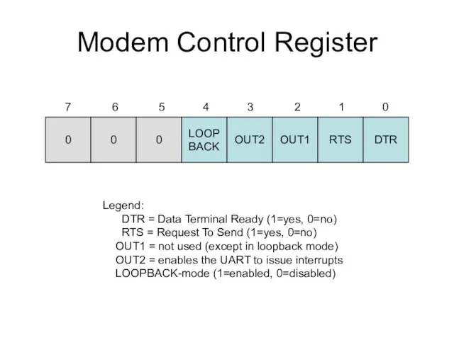
Modem Control Register
0
0
0
LOOP
BACK
OUT2
OUT1
RTS
DTR
7 6 5 4 3 2 1 0
Legend:
DTR
Modem Control Register
0
0
0
LOOP
BACK
OUT2
OUT1
RTS
DTR
7 6 5 4 3 2 1 0
Legend:
DTR
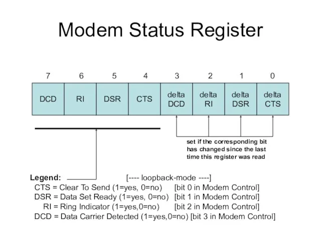
Modem Status Register
DCD
RI
DSR
CTS
delta
DCD
delta
RI
delta
DSR
delta
CTS
7 6 5 4 3 2 1 0
set
Modem Status Register
DCD
RI
DSR
CTS
delta
DCD
delta
RI
delta
DSR
delta
CTS
7 6 5 4 3 2 1 0
set
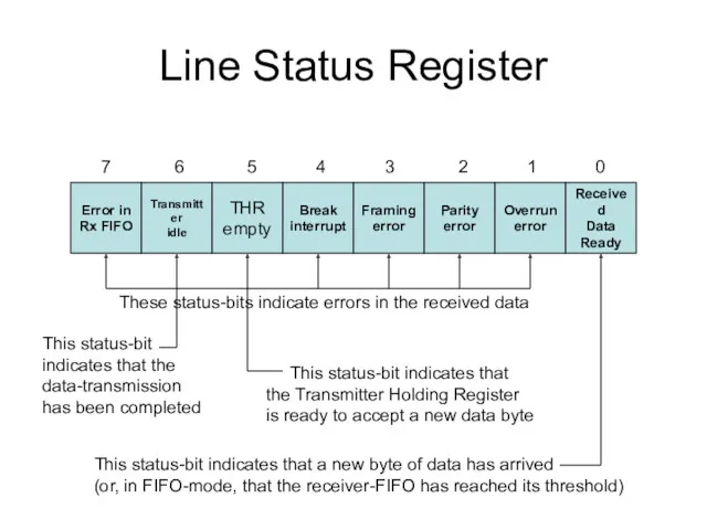
Line Status Register
Error in
Rx FIFO
Transmitter
idle
THR
empty
Break
interrupt
Framing
error
Parity
error
Overrun
error
Received
Data
Ready
7 6 5 4 3 2 1
Line Status Register
Error in
Rx FIFO
Transmitter
idle
THR
empty
Break
interrupt
Framing
error
Parity
error
Overrun
error
Received
Data
Ready
7 6 5 4 3 2 1
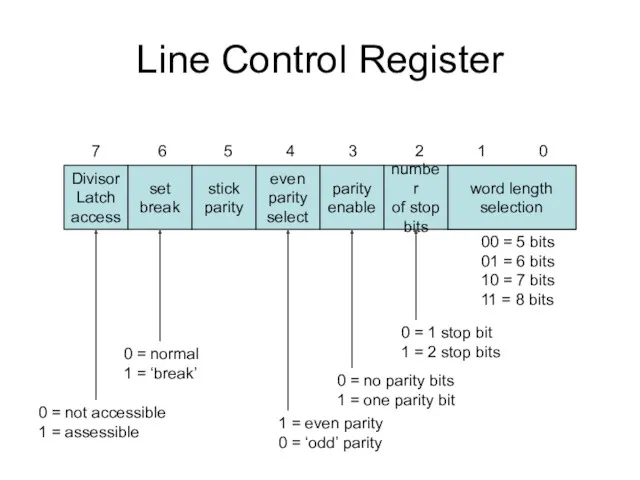
Line Control Register
Divisor
Latch
access
set
break
stick
parity
even
parity
select
parity
enable
number
of stop
bits
word length
selection
7 6 5 4 3 2
Line Control Register
Divisor
Latch
access
set
break
stick
parity
even
parity
select
parity
enable
number
of stop
bits
word length
selection
7 6 5 4 3 2
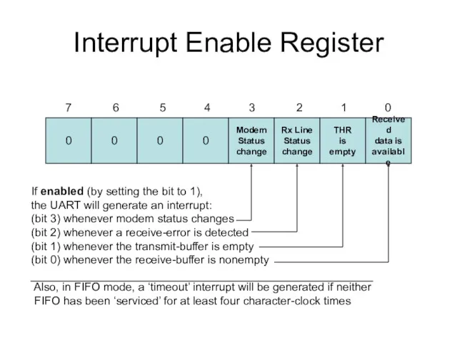
Interrupt Enable Register
0
0
0
0
Modem
Status
change
Rx Line
Status
change
THR
is
empty
Received
data is
available
7 6 5 4 3 2 1
Interrupt Enable Register
0
0
0
0
Modem
Status
change
Rx Line
Status
change
THR
is
empty
Received
data is
available
7 6 5 4 3 2 1
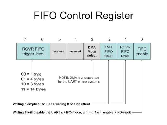
FIFO Control Register
RCVR FIFO
trigger-level
reserved
reserved
DMA
Mode
select
XMIT
FIFO
reset
RCVR
FIFO
reset
FIFO
enable
7 6 5 4 3 2 1 0
Writing
FIFO Control Register
RCVR FIFO
trigger-level
reserved
reserved
DMA
Mode
select
XMIT
FIFO
reset
RCVR
FIFO
reset
FIFO
enable
7 6 5 4 3 2 1 0
Writing
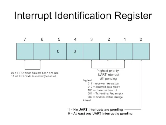
Interrupt Identification Register
0
0
7 6 5 4 3 2 1 0
00
Interrupt Identification Register
0
0
7 6 5 4 3 2 1 0
00
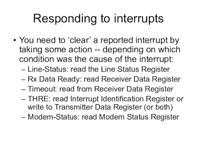
Responding to interrupts
You need to ‘clear’ a reported interrupt by taking
Responding to interrupts
You need to ‘clear’ a reported interrupt by taking
Usage flexibility
A UART can be programmed to operate in “polled” mode
Usage flexibility
A UART can be programmed to operate in “polled” mode
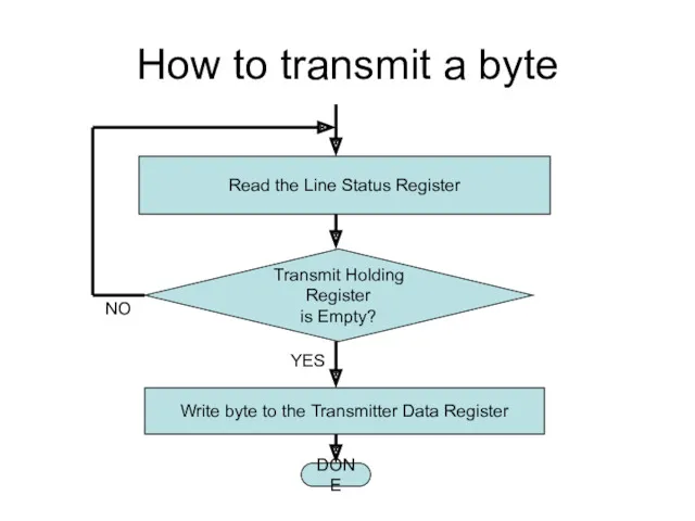
How to transmit a byte
Read the Line Status Register
Write byte to
How to transmit a byte
Read the Line Status Register
Write byte to
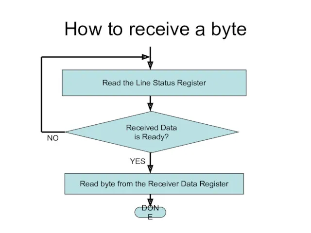
How to receive a byte
Read the Line Status Register
Read byte from
How to receive a byte
Read the Line Status Register
Read byte from
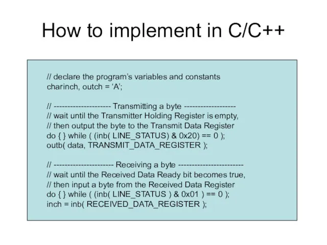
How to implement in C/C++
// declare the program’s variables and constants
char inch,
How to implement in C/C++
// declare the program’s variables and constants
char inch,
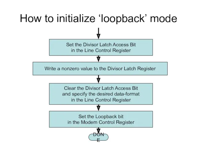
How to initialize ‘loopback’ mode
Set the Divisor Latch Access Bit
in the
How to initialize ‘loopback’ mode
Set the Divisor Latch Access Bit
in the
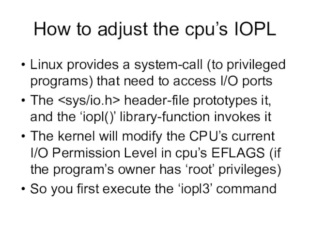
How to adjust the cpu’s IOPL
Linux provides a system-call (to
How to adjust the cpu’s IOPL
Linux provides a system-call (to
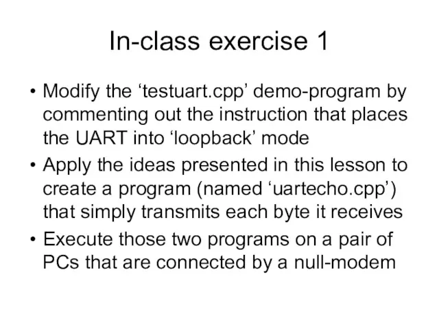
In-class exercise 1
Modify the ‘testuart.cpp’ demo-program by commenting out the instruction
In-class exercise 1
Modify the ‘testuart.cpp’ demo-program by commenting out the instruction
In-class exercise 2
Add a pair of counters to ‘testuart.cpp’:
Declare two integer
In-class exercise 2
Add a pair of counters to ‘testuart.cpp’:
Declare two integer
 Программное обеспечение ПК
 Модификация базы данных студенты
 Open Cascade VPN. Installation and activation manual
 CSS basics
 Электронные таблицы Excel 2007. Средства анализа данных
 Школа блогеров (инструкция)
 Игра. Условное представление.часть1
 Значение коммуникации в управлении организацией
 Устройство компьютера. История развития вычислительной техники
 Безопасность персональных данных в сети Интернет
 Организация циклов на языке Pascal
 Применение информационных технологий для научных исследований в области земельного, природоресурсного, аграрного права
 Автоматизация процессного управления
 Компания Century Star Media Co
 Оформление цитат, списка литературы, библиографических ссылок
 Графічні об’єкти в текстовому документі
 Лабораторные работы
 Как устроена книга
 Конфигурация Весовая ред. 3.0 на платформе 1С: Предприятие 8.3
 Право и этика СМИ
 Использование интернет-банкинга
 Текстовые документы и технологии их создания. Обработка текстовой информации. Информатика и ИКТ. 8 класс
 Обработка рисунков и фотографий Adobe Photoshop. Создание презентации PowerPoint
 Аутсорсинг логистики электронной торговли
 IP-адрес
 Примеры решения задания 14, ОГЭ по информатике
 Алгоритм и его свойства
 Технические каналы утечки акустической информации