- Control and monitoring system (CMS)

Содержание
- 2. WARNING OF CONFIDENTIALITY Warning of Confidentiality Indra owns the copyright of this document which is supplied
- 3. REVISED PREPARED DATE NAME/SIGNATURE DATE NAME/SIGNATURE DATE NAME/SIGNATURE CUSTOMER PROJECT MANAGER PARTICIPATING CO. APPROVED AUTHORIZED DOCUMENTATION
- 4. REASON OF THE CHANGES AFFECTED PAGES DATE REVISION EDITION REVISION EDITION PAGE DOCUMENT CHANGES RECORD PAGE
- 5. ACRONYMS ACP Azimuth Change Pulse ARP Azimuth Reset Pulse AST Asterix ASTERIX All Purpose STructured Eurocontrol
- 6. ACRONYMS NTP Network Time Protocol PA Power Amplifier PED Pedestal POL Polarization PPI Plan Position Indicators
- 7. ACRONYMS UDP User Datagram Protocol VSWR Video Standing Wave Ratio WAN Wide Area Network WCD Waveguide
- 8. INDEX 01 General Description System Overview Block Diagram Functional Description 02 Description of Elements PSR CMS
- 9. GENERAL DESCRIPTION System Overview Control and Monitoring System (CMS) consist of: SLG equipments, located at the
- 10. GENERAL DESCRIPTION Block Diagram Control and Monitoring Systems
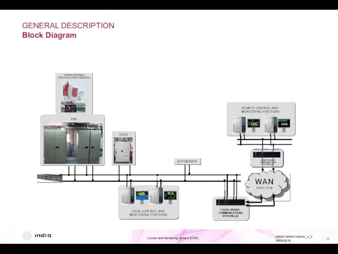
- 11. GENERAL DESCRIPTION Block Diagram
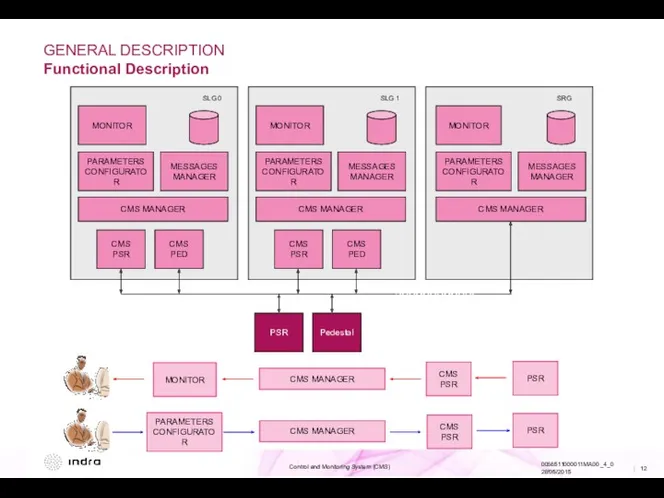
- 12. GENERAL DESCRIPTION Functional Description MONITOR PARAMETERS CONFIGURATOR MESSAGES MANAGER CMS MANAGER CMS PSR CMS PED PSR
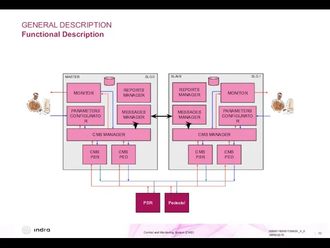
- 13. GENERAL DESCRIPTION Functional Description MONITOR PARAMETERS CONFIGURATOR MESSAGES MANAGER CMS MANAGER CMS PSR CMS PED SLG
- 14. GENERAL DESCRIPTION Functional Description The main functions of Local Management System are: CONTROL: Allows user to
- 15. INDEX 01 General Description System Overview Block Diagram Functional Description 02 Description of Elements PSR CMS
- 16. DESCRIPTION OF ELEMENTS PSR CMS Main Screen CMS PSR Features: System Control. Complete System Monitoring. Check
- 17. DESCRIPTION OF ELEMENTS Pedestal CMS Main Screen Pedestal CMS Features: System Control. Complete System Monitoring. Check
- 18. INDEX 01 General Description System Overview Block Diagram Functional Description 02 Description of Elements PSR CMS
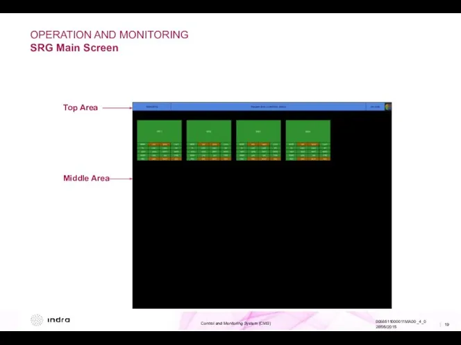
- 19. OPERATION AND MONITORING SRG Main Screen Top Area Middle Area
- 20. OPERATION AND MONITORING SRG Main Screen The main screen of the SRG shows two different areas:
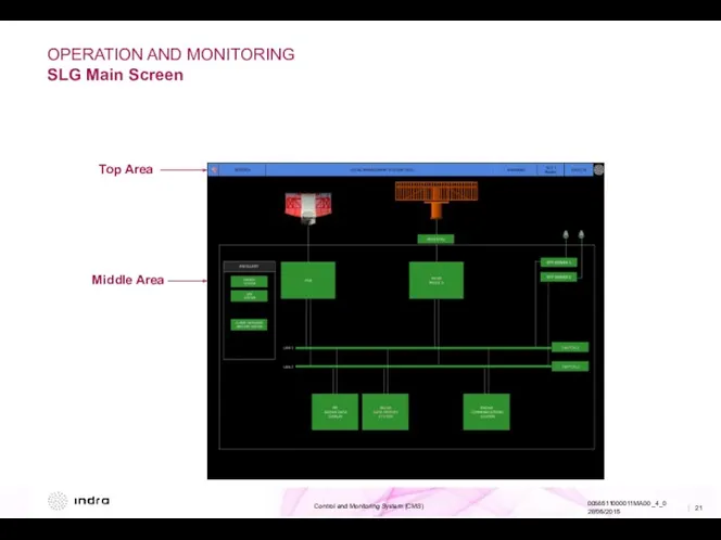
- 21. OPERATION AND MONITORING SLG Main Screen Top Area Middle Area
- 22. OPERATION AND MONITORING SLG Main Screen The main screen of the SLG level shows two different
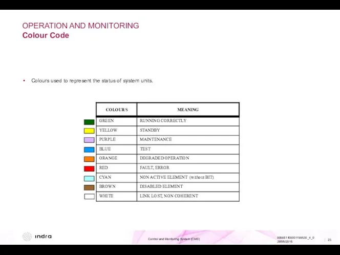
- 23. OPERATION AND MONITORING Colour Code Colours used to represent the status of system units.
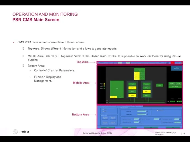
- 24. OPERATION AND MONITORING PSR CMS Main Screen Top Area Middle Area Bottom Area CMS PSR main
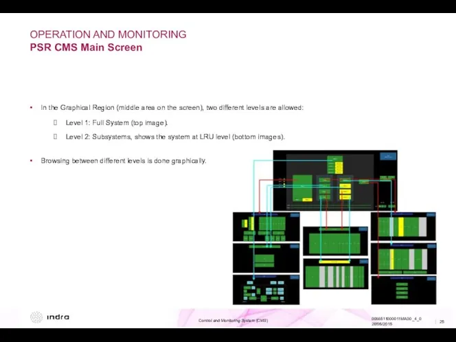
- 25. OPERATION AND MONITORING PSR CMS Main Screen In the Graphical Region (middle area on the screen),
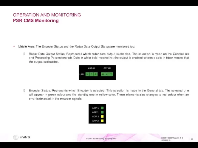
- 26. OPERATION AND MONITORING PSR CMS Monitoring Middle Area: The Encoder Status and the Radar Data Output
- 27. OPERATION AND MONITORING PSR CMS Monitoring Middle Area: It is where system and subsystems (up to
- 28. OPERATION AND MONITORING PSR CMS Monitoring In GRPG Group will appear a different monitoring screen depending
- 29. OPERATION AND MONITORING PSR CMS Monitoring Monitoring of WCD: All four possible alarms are indicated in
- 30. OPERATION AND MONITORING PSR CMS Operation Reports Button: Allows to generate failure and event reports. Faults
- 31. OPERATION AND MONITORING PSR CMS Operation On the Bottom Area of CMS, there are some tabs
- 32. OPERATION AND MONITORING PSR CMS Operation Available tabs: General: General system controls. TXG: Transmitter Group controls.
- 33. OPERATION AND MONITORING PSR CMS Operation Main Tab: General settings. TX On/ TX Off Transmission. Azimuth
- 34. OPERATION AND MONITORING PSR CMS Operation TXG Tab: Control of Transmitter Group. Switch On/Off PA’s: Each
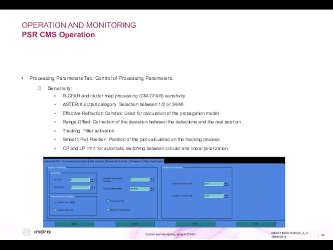
- 35. OPERATION AND MONITORING PSR CMS Operation Processing Parameters Tab: Control of Processing Parameters. Sensitivity: R-CFAR and
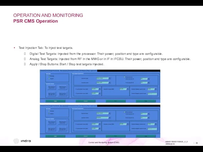
- 36. OPERATION AND MONITORING PSR CMS Operation Test Injection Tab: To inject test targets. Digital Test Targets:
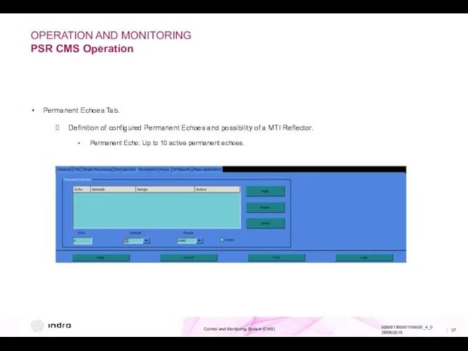
- 37. OPERATION AND MONITORING PSR CMS Operation Permanent Echoes Tab. Definition of configured Permanent Echoes and possibility
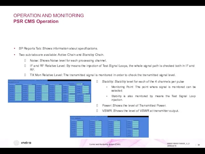
- 38. OPERATION AND MONITORING PSR CMS Operation SP Reports Tab: Shows information about specifications. Two sub-tabs are
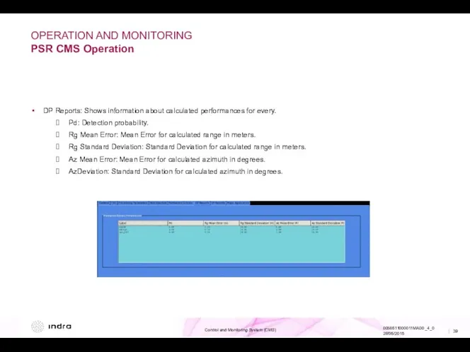
- 39. OPERATION AND MONITORING PSR CMS Operation DP Reports: Shows information about calculated performances for every. Pd:
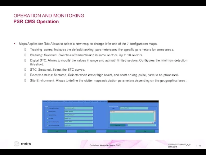
- 40. OPERATION AND MONITORING PSR CMS Operation Maps Application Tab: Allows to select a new map, to
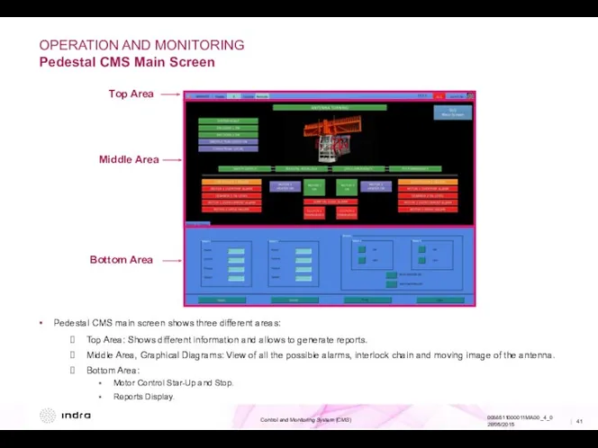
- 41. OPERATION AND MONITORING Pedestal CMS Main Screen Top Area Middle Area Bottom Area Pedestal CMS main
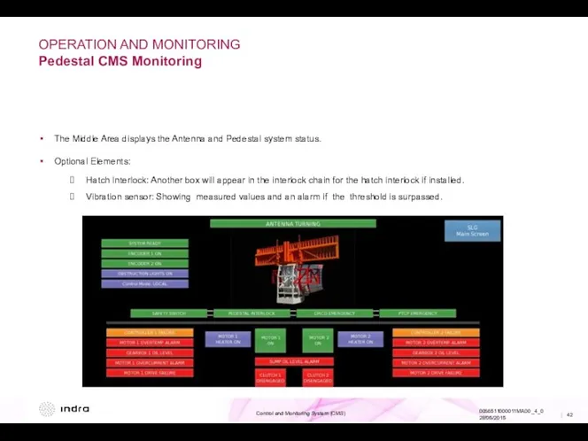
- 42. OPERATION AND MONITORING Pedestal CMS Monitoring The Middle Area displays the Antenna and Pedestal system status.
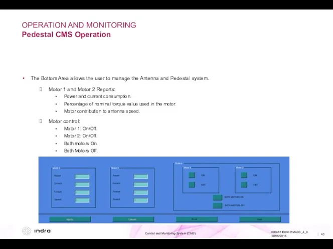
- 43. OPERATION AND MONITORING Pedestal CMS Operation The Bottom Area allows the user to manage the Antenna
- 45. Скачать презентацию

WARNING OF CONFIDENTIALITY
Warning of Confidentiality
Indra owns the copyright of this document
WARNING OF CONFIDENTIALITY
Warning of Confidentiality
Indra owns the copyright of this document
REVISED
PREPARED
DATE
NAME/SIGNATURE
DATE
NAME/SIGNATURE
DATE
NAME/SIGNATURE
CUSTOMER PROJECT MANAGER
PARTICIPATING CO.
APPROVED
AUTHORIZED
DOCUMENTATION CONTROL
REVISED
PREPARED
DATE
NAME/SIGNATURE
DATE
NAME/SIGNATURE
DATE
NAME/SIGNATURE
CUSTOMER PROJECT MANAGER
PARTICIPATING CO.
APPROVED
AUTHORIZED
DOCUMENTATION CONTROL
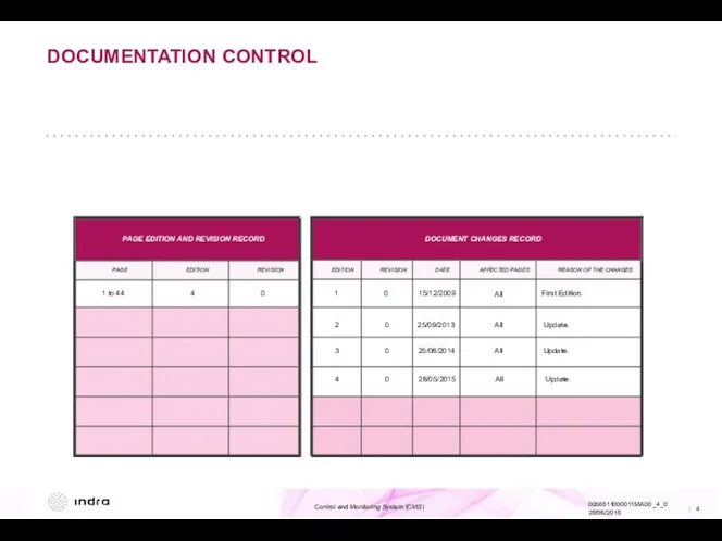
REASON OF THE CHANGES
AFFECTED PAGES
DATE
REVISION
EDITION
REVISION
EDITION
PAGE
DOCUMENT CHANGES RECORD
PAGE EDITION AND REVISION RECORD
1
REASON OF THE CHANGES
AFFECTED PAGES
DATE
REVISION
EDITION
REVISION
EDITION
PAGE
DOCUMENT CHANGES RECORD
PAGE EDITION AND REVISION RECORD
1
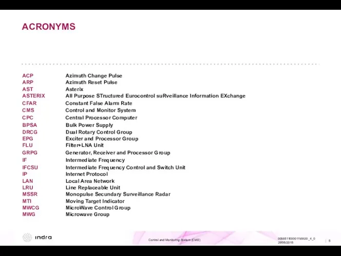
ACRONYMS
ACP Azimuth Change Pulse
ARP Azimuth Reset Pulse
AST Asterix
ASTERIX All Purpose STructured Eurocontrol suRveillance Information EXchange
CFAR Constant
ACRONYMS
ACP Azimuth Change Pulse
ARP Azimuth Reset Pulse
AST Asterix
ASTERIX All Purpose STructured Eurocontrol suRveillance Information EXchange
CFAR Constant
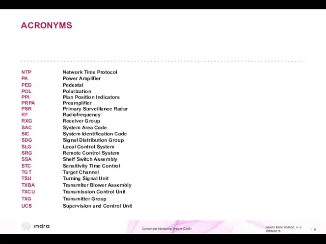
ACRONYMS
NTP Network Time Protocol
PA Power Amplifier
PED Pedestal
POL Polarization
PPI Plan Position Indicators
PRPA Preamplifier
PSR Primary Surveillance Radar
RF Radiofrequency
RXG Receiver Group
SAC System Area Code
SIC System
ACRONYMS
NTP Network Time Protocol
PA Power Amplifier
PED Pedestal
POL Polarization
PPI Plan Position Indicators
PRPA Preamplifier
PSR Primary Surveillance Radar
RF Radiofrequency
RXG Receiver Group
SAC System Area Code
SIC System
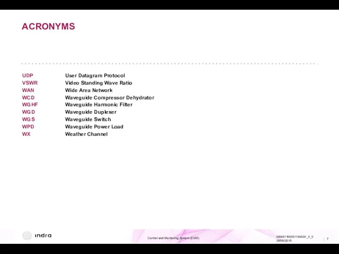
ACRONYMS
UDP User Datagram Protocol
VSWR Video Standing Wave Ratio
WAN Wide Area Network
WCD Waveguide Compressor Dehydrator
WGHF Waveguide Harmonic
ACRONYMS
UDP User Datagram Protocol
VSWR Video Standing Wave Ratio
WAN Wide Area Network
WCD Waveguide Compressor Dehydrator
WGHF Waveguide Harmonic
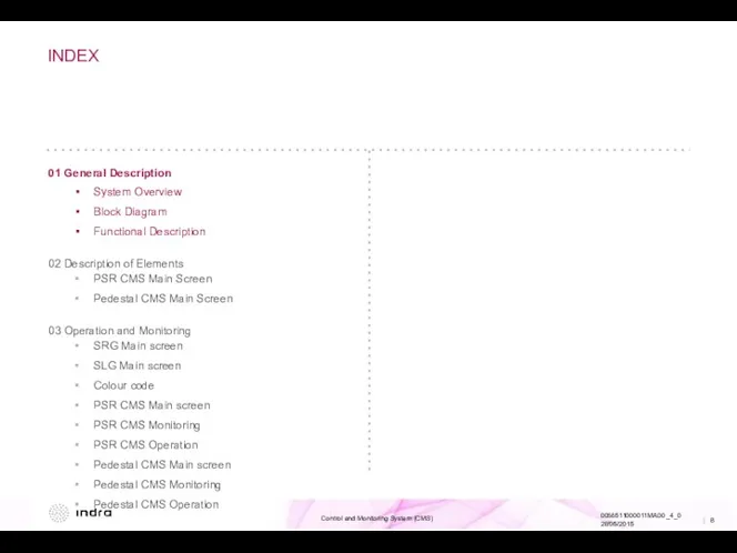
INDEX
01 General Description
System Overview
Block Diagram
Functional Description
02 Description of Elements
PSR CMS Main
INDEX
01 General Description
System Overview
Block Diagram
Functional Description
02 Description of Elements
PSR CMS Main
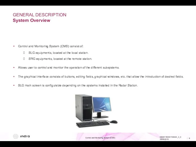
GENERAL DESCRIPTION
System Overview
Control and Monitoring System (CMS) consist of:
SLG equipments, located
GENERAL DESCRIPTION
System Overview
Control and Monitoring System (CMS) consist of:
SLG equipments, located
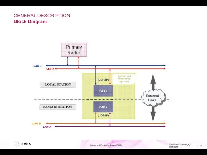
GENERAL DESCRIPTION
Block Diagram
Control and Monitoring Systems
GENERAL DESCRIPTION
Block Diagram
Control and Monitoring Systems
GENERAL DESCRIPTION
Block Diagram
GENERAL DESCRIPTION
Block Diagram
GENERAL DESCRIPTION
Functional Description
MONITOR
PARAMETERS
CONFIGURATOR
MESSAGES
MANAGER
CMS MANAGER
CMS PSR
CMS PED
PSR
Pedestal
SLG 0
MONITOR
SRG
MONITOR
CMS MANAGER
CMS PSR
PSR
CMS MANAGER
CMS PSR
PSR
MONITOR
PARAMETERS
CONFIGURATOR
MESSAGES
MANAGER
CMS
GENERAL DESCRIPTION
Functional Description
MONITOR
PARAMETERS
CONFIGURATOR
MESSAGES
MANAGER
CMS MANAGER
CMS PSR
CMS PED
PSR
Pedestal
SLG 0
MONITOR
SRG
MONITOR
CMS MANAGER
CMS PSR
PSR
CMS MANAGER
CMS PSR
PSR
MONITOR
PARAMETERS
CONFIGURATOR
MESSAGES
MANAGER
CMS
GENERAL DESCRIPTION
Functional Description
MONITOR
PARAMETERS
CONFIGURATOR
MESSAGES
MANAGER
CMS MANAGER
CMS PSR
CMS PED
SLG 0
MASTER
PSR
Pedestal
MONITOR
PARAMETERS
CONFIGURATOR
MESSAGES
MANAGER
CMS MANAGER
CMS PSR
CMS PED
SLG 1
SLAVE
REPORTS
MANAGER
REPORTS
MANAGER
GENERAL DESCRIPTION
Functional Description
MONITOR
PARAMETERS
CONFIGURATOR
MESSAGES
MANAGER
CMS MANAGER
CMS PSR
CMS PED
SLG 0
MASTER
PSR
Pedestal
MONITOR
PARAMETERS
CONFIGURATOR
MESSAGES
MANAGER
CMS MANAGER
CMS PSR
CMS PED
SLG 1
SLAVE
REPORTS
MANAGER
REPORTS
MANAGER
GENERAL DESCRIPTION
Functional Description
The main functions of Local Management System are:
CONTROL: Allows
GENERAL DESCRIPTION
Functional Description
The main functions of Local Management System are:
CONTROL: Allows
INDEX
01 General Description
System Overview
Block Diagram
Functional Description
02 Description of Elements
PSR CMS Main
INDEX
01 General Description
System Overview
Block Diagram
Functional Description
02 Description of Elements
PSR CMS Main
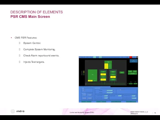
DESCRIPTION OF ELEMENTS
PSR CMS Main Screen
CMS PSR Features:
System Control.
Complete System Monitoring.
Check
DESCRIPTION OF ELEMENTS
PSR CMS Main Screen
CMS PSR Features:
System Control.
Complete System Monitoring.
Check
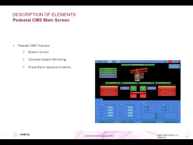
DESCRIPTION OF ELEMENTS
Pedestal CMS Main Screen
Pedestal CMS Features:
System Control.
Complete System Monitoring.
Check
DESCRIPTION OF ELEMENTS
Pedestal CMS Main Screen
Pedestal CMS Features:
System Control.
Complete System Monitoring.
Check
INDEX
01 General Description
System Overview
Block Diagram
Functional Description
02 Description of Elements
PSR CMS Main
INDEX
01 General Description
System Overview
Block Diagram
Functional Description
02 Description of Elements
PSR CMS Main
OPERATION AND MONITORING
SRG Main Screen
Top Area
Middle Area
OPERATION AND MONITORING
SRG Main Screen
Top Area
Middle Area
OPERATION AND MONITORING
SRG Main Screen
The main screen of the SRG shows
OPERATION AND MONITORING
SRG Main Screen
The main screen of the SRG shows
OPERATION AND MONITORING
SLG Main Screen
Top Area
Middle Area
OPERATION AND MONITORING
SLG Main Screen
Top Area
Middle Area
OPERATION AND MONITORING
SLG Main Screen
The main screen of the SLG level
OPERATION AND MONITORING
SLG Main Screen
The main screen of the SLG level
OPERATION AND MONITORING
Colour Code
Colours used to represent the status of system
OPERATION AND MONITORING
Colour Code
Colours used to represent the status of system
OPERATION AND MONITORING
PSR CMS Main Screen
Top Area
Middle Area
Bottom Area
CMS PSR main
OPERATION AND MONITORING
PSR CMS Main Screen
Top Area
Middle Area
Bottom Area
CMS PSR main
OPERATION AND MONITORING
PSR CMS Main Screen
In the Graphical Region (middle area
OPERATION AND MONITORING
PSR CMS Main Screen
In the Graphical Region (middle area
OPERATION AND MONITORING
PSR CMS Monitoring
Middle Area: The Encoder Status and the
OPERATION AND MONITORING
PSR CMS Monitoring
Middle Area: The Encoder Status and the
OPERATION AND MONITORING
PSR CMS Monitoring
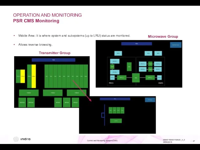
Middle Area: It is where system and
OPERATION AND MONITORING
PSR CMS Monitoring
Middle Area: It is where system and
OPERATION AND MONITORING
PSR CMS Monitoring
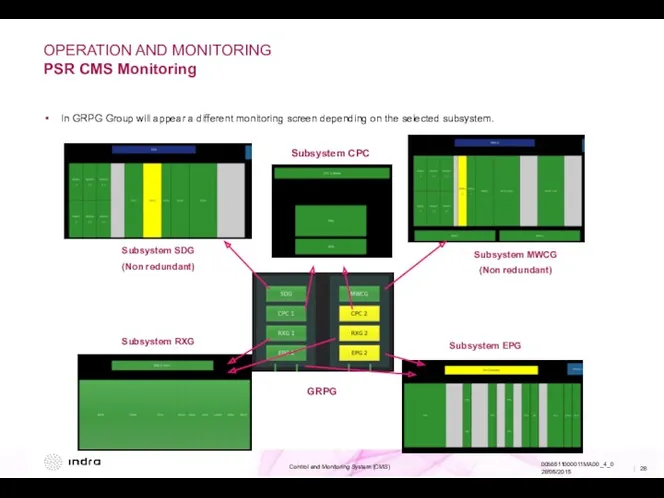
In GRPG Group will appear a different
OPERATION AND MONITORING
PSR CMS Monitoring
In GRPG Group will appear a different
OPERATION AND MONITORING
PSR CMS Monitoring
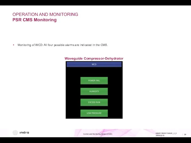
Monitoring of WCD: All four possible alarms
OPERATION AND MONITORING
PSR CMS Monitoring
Monitoring of WCD: All four possible alarms
OPERATION AND MONITORING
PSR CMS Operation
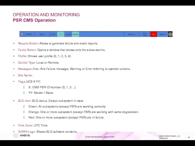
Reports Button: Allows to generate failure and
OPERATION AND MONITORING
PSR CMS Operation
Reports Button: Allows to generate failure and
OPERATION AND MONITORING
PSR CMS Operation
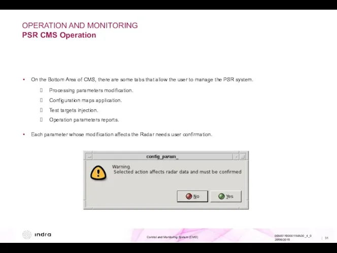
On the Bottom Area of CMS, there
OPERATION AND MONITORING
PSR CMS Operation
On the Bottom Area of CMS, there
OPERATION AND MONITORING
PSR CMS Operation
Available tabs:
General: General system controls.
TXG: Transmitter Group
OPERATION AND MONITORING
PSR CMS Operation
Available tabs:
General: General system controls.
TXG: Transmitter Group
OPERATION AND MONITORING
PSR CMS Operation
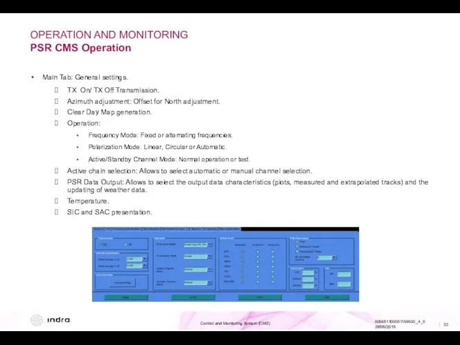
Main Tab: General settings.
TX On/ TX Off
OPERATION AND MONITORING
PSR CMS Operation
Main Tab: General settings.
TX On/ TX Off
OPERATION AND MONITORING
PSR CMS Operation
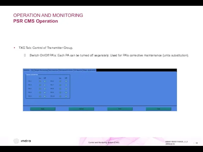
TXG Tab: Control of Transmitter Group.
Switch On/Off
OPERATION AND MONITORING
PSR CMS Operation
TXG Tab: Control of Transmitter Group.
Switch On/Off
OPERATION AND MONITORING
PSR CMS Operation
Processing Parameters Tab: Control of Processing Parameters.
Sensitivity:
R-CFAR
OPERATION AND MONITORING
PSR CMS Operation
Processing Parameters Tab: Control of Processing Parameters.
Sensitivity:
R-CFAR
OPERATION AND MONITORING
PSR CMS Operation
Test Injection Tab: To inject test targets.
Digital
OPERATION AND MONITORING
PSR CMS Operation
Test Injection Tab: To inject test targets.
Digital
OPERATION AND MONITORING
PSR CMS Operation
Permanent Echoes Tab.
Definition of configured Permanent Echoes
OPERATION AND MONITORING
PSR CMS Operation
Permanent Echoes Tab.
Definition of configured Permanent Echoes
OPERATION AND MONITORING
PSR CMS Operation
SP Reports Tab: Shows information about specifications.
OPERATION AND MONITORING
PSR CMS Operation
SP Reports Tab: Shows information about specifications.
OPERATION AND MONITORING
PSR CMS Operation
DP Reports: Shows information about calculated performances
OPERATION AND MONITORING
PSR CMS Operation
DP Reports: Shows information about calculated performances
OPERATION AND MONITORING
PSR CMS Operation
Maps Application Tab: Allows to select a
OPERATION AND MONITORING
PSR CMS Operation
Maps Application Tab: Allows to select a
OPERATION AND MONITORING
Pedestal CMS Main Screen
Top Area
Middle Area
Bottom Area
Pedestal CMS main
OPERATION AND MONITORING
Pedestal CMS Main Screen
Top Area
Middle Area
Bottom Area
Pedestal CMS main
OPERATION AND MONITORING
Pedestal CMS Monitoring
The Middle Area displays the Antenna and
OPERATION AND MONITORING
Pedestal CMS Monitoring
The Middle Area displays the Antenna and
OPERATION AND MONITORING
Pedestal CMS Operation
The Bottom Area allows the user to
OPERATION AND MONITORING
Pedestal CMS Operation
The Bottom Area allows the user to
 Электронно-библиотечные системы. Лекция 6
 Программирование линейных алгоритмов
 Сервисы интернета
 Урок обобщение знаний Объекты окружающего мира, Компьютерные объекты 6 класс, учебник Босова Л.Л.
 Безопасность в интернете
 Программирование на Python
 Электронное правительство
 54. Layouts в Android. Класс Handler, таймеры, типы макетов
 Администрирование в ЛВС
 Дискретная математика: теория алгоритмов и сложность вычислений
 Среда программирования Кумир. Чертежник
 Операционная система. Программное обеспечение компьютера
 Имена и типы файлов
 Угрозы информации
 Урок Табличное решение логических задач
 Перспективы развития средств фундаментального и метрологического обеспечения системы ГЛОНАСС
 Створення БД у режимі майстра
 Selenium RC
 Digital Civility 2021 Global Report
 Язык Паскаль
 Персональные данные и их защита
 Теория информации. Энтропия и информация
 Install Apache Cassandra on Ubuntu. Work with Cassandra and Python
 Классы и объекты
 Этика в Интернете. 11 класс
 Использование информационно-коммуникационных технологий на уроках русского языка и литературы
 Классификация вредоносных, нежелательных и условно опасных программ
 Мир информатики. Своя игра