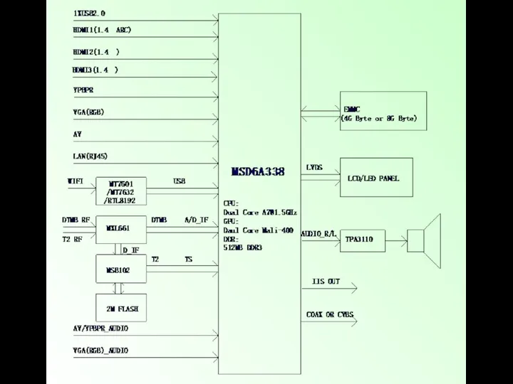
- CV338H-T42. Common problems solution

Содержание
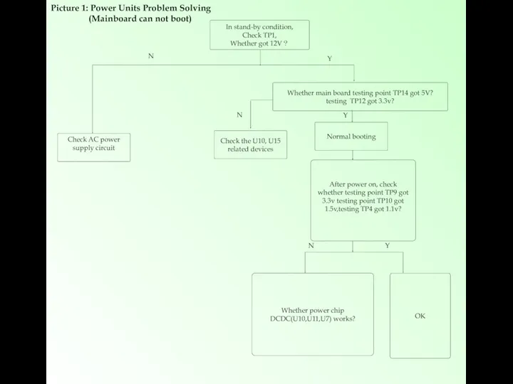
- 3. In stand-by condition, Check TP1, Whether got 12V? Normal booting Whether power chip DCDC(U10,U11,U7) works? After
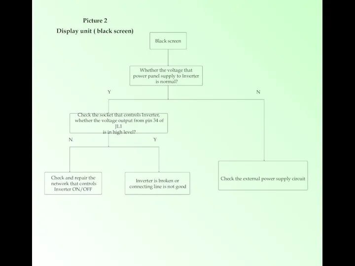
- 4. Black screen Whether the voltage that power panel supply to Inverter is normal? Check the socket
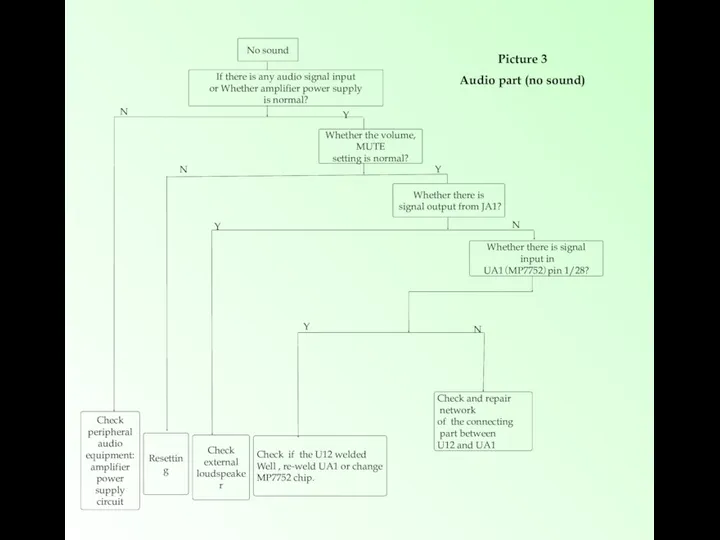
- 5. No sound If there is any audio signal input or Whether amplifier power supply is normal?
- 6. TV no searching /no image Picture 4 T2+T+C Function unit (ATV/DTV video broke down) Check whether
- 7. TV no sound, only picture Whether there is sound under PC AV? N Y Refer to
- 8. Under PC Image not in the middle Miss color, Color cast Image shakes No signal Carry
- 10. Скачать презентацию
In stand-by condition,
Check TP1,
Whether got 12V?
Normal booting
Whether power chip DCDC(U10,U11,U7) works?
After
In stand-by condition,
Check TP1,
Whether got 12V?
Normal booting
Whether power chip DCDC(U10,U11,U7) works?
After
Black screen
Whether the voltage that
power panel supply to Inverter
is
Black screen
Whether the voltage that
power panel supply to Inverter
is
No sound
If there is any audio signal input
or Whether amplifier
No sound
If there is any audio signal input
or Whether amplifier
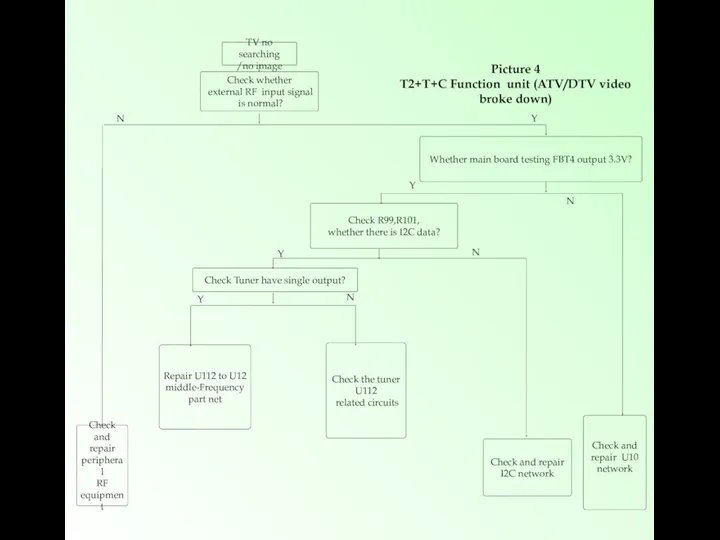
TV no searching
/no image
Picture 4
T2+T+C Function unit (ATV/DTV video broke down)
Check
TV no searching
/no image
Picture 4
T2+T+C Function unit (ATV/DTV video broke down)
Check
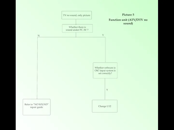
TV no sound, only picture
Whether there is
sound under PC AV?
N
Y
Refer
TV no sound, only picture
Whether there is
sound under PC AV?
N
Y
Refer
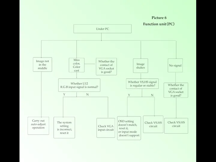
Under PC
Image not
in the middle
Miss color,
Color
cast
Image
shakes
No signal
Carry out
Under PC
Image not
in the middle
Miss color,
Color
cast
Image
shakes
No signal
Carry out
 Git Система контроля версий
 Система автоматизации CitRus. Функциональные возможности и преимущества
 Алгоритмизация. Понятие алгоритма
 Компьютерлік модель. Компьютерде модельдерді зерттеу
 Штриховой код
 Программирование ветвлений
 Архитектура 32-битных Intel-совместимых микропроцессоров (1) (1)
 Инструкция по работе для перевозчиков. Smart tendering
 Қолданбалы бағдарламалар
 Использование массивов и табличных формул. Операции с матрицами. Решение систем линейных уравнений. (Лекция 8)
 Электронная цифровая подпись (ЭЦП)
 Программирование на языке Python. Символьные строки
 Представление данных и операции. Основы программирования. (Тема 1.2)
 Интернет
 Использование среды Visual Basic для создания прикладных программ
 Топ-10 посещаемых мною сайтов
 Как подготовить эффективную презентацию
 Ethernet желілік технологиясы
 Кодирование графической информации
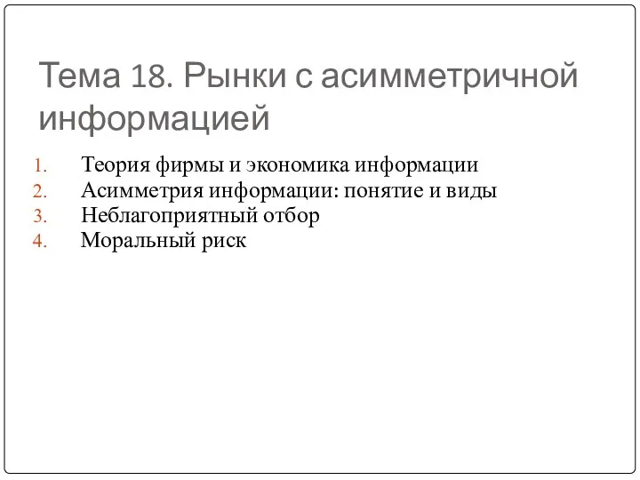 Рынки с асимметричной информацией
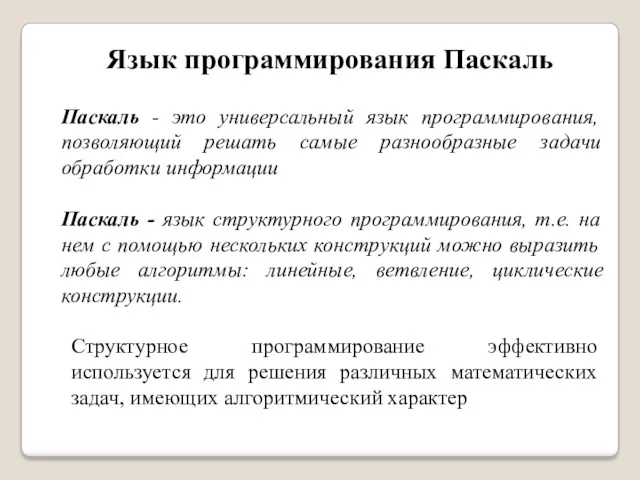 Язык программирования Паскаль
 By Herber
 Презентация Эволюция лирического героя в творчестве А.Блока
 Документ как система
 Технологии программирования
 Файлы. Функции для работы с файлами
 Перевод чисел в позиционных системах счисления
 Введение в постановку целей и задач в разработке ПО. Лекция 1