- Data Networks: Introduction

Содержание
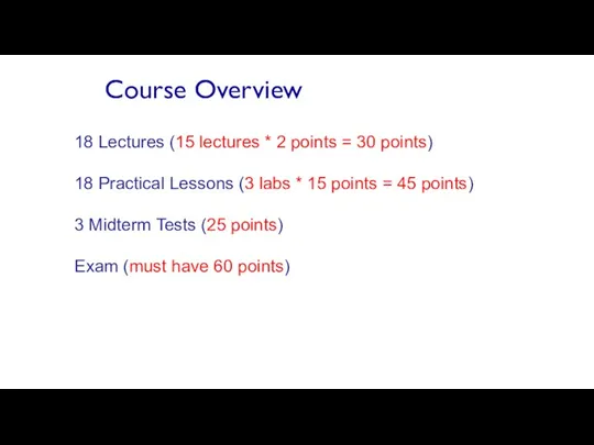
- 2. Course Overview 18 Lectures (15 lectures * 2 points = 30 points) 18 Practical Lessons (3
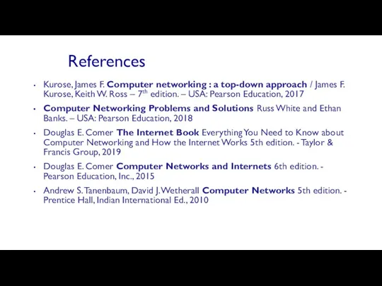
- 3. References Kurose, James F. Computer networking : a top-down approach / James F. Kurose, Keith W.
- 4. Study Tools Lecture PPTs, Labs, Additional materials: https://jointvlab.ipt.pt/moodle/ Wireshark, Packet Tracer
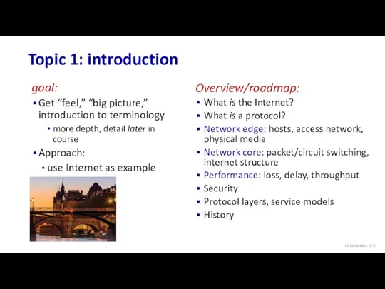
- 5. Topic 1: introduction goal: Get “feel,” “big picture,” introduction to terminology more depth, detail later in
- 6. Internet The Internet: a “nuts and bolts” view Introduction: 1-
- 7. “Fun” Internet-connected devices Introduction: 1- IP picture frame Web-enabled toaster + weather forecaster Internet phones Slingbox:
- 8. Internet: “network of networks” Interconnected ISPs The Internet: a “nuts and bolts” view Introduction: 1- mobile
- 9. Infrastructure that provides services to applications: Web, streaming video, multimedia teleconferencing, email, games, e-commerce, social media,
- 10. What’s a protocol? Introduction: 1- Human protocols: “what’s the time?” “I have a question” introductions …
- 11. What’s a protocol? Introduction: 1- A human protocol and a computer network protocol: Q: other human
- 12. Topic 1: roadmap Introduction: 1- What is the Internet? What is a protocol? Network edge: hosts,
- 13. A closer look at Internet structure Introduction: 1- Network edge: hosts: clients and servers servers often
- 14. A closer look at Internet structure Introduction: 1- mobile network home network enterprise network national or
- 15. A closer look at Internet structure Network edge: hosts: clients and servers servers often in data
- 16. Access networks and physical media Introduction: 1- mobile network home network enterprise network national or global
- 17. Access networks: cable-based access Introduction: 1- cable modem splitter … cable headend frequency division multiplexing (FDM):
- 18. Access networks: cable-based access Introduction: 1- cable modem splitter … cable headend HFC: hybrid fiber coax
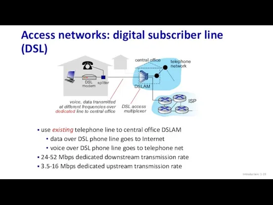
- 19. Introduction: 1- Access networks: digital subscriber line (DSL) central office telephone network DSLAM use existing telephone
- 20. Introduction: 1- Access networks: home networks to/from headend or central office wireless devices
- 21. Introduction: 1- Wireless access networks Shared wireless access network connects end system to router via base
- 22. Introduction: 1- Access networks: enterprise networks companies, universities, etc. mix of wired, wireless link technologies, connecting
- 23. Introduction: 1- Host: sends packets of data host sending function: takes application message breaks into smaller
- 24. Introduction: 1- Links: physical media bit: propagates between transmitter/receiver pairs physical link: what lies between transmitter
- 25. Introduction: 1- Links: physical media Coaxial cable: two concentric copper conductors bidirectional broadband: multiple frequency channels
- 26. Introduction: 1- Links: physical media Wireless radio signal carried in electromagnetic spectrum no physical “wire” broadcast
- 27. Topic 1: roadmap Introduction: 1- What is the Internet? What is a protocol? Network edge: hosts,
- 28. The network core mesh of interconnected routers packet-switching: hosts break application-layer messages into packets forward packets
- 29. Packet-switching: store-and-forward Transmission delay: takes L/R seconds to transmit (push out) L-bit packet into link at
- 30. Packet-switching: queueing delay, loss Packet queuing and loss: if arrival rate (in bps) to link exceeds
- 31. Two key network-core functions Introduction: 1- Forwarding: local action: move arriving packets from router’s input link
- 32. Alternative to packet switching: circuit switching end-end resources allocated to, reserved for “call” between source and
- 33. Circuit switching: FDM and TDM Introduction: 1- Frequency Division Multiplexing (FDM) optical, electromagnetic frequencies divided into
- 34. Packet switching versus circuit switching Introduction: 1- Example: 1 Gb/s link each user: 100 Mb/s when
- 35. Packet switching versus circuit switching Introduction: 1- great for “bursty” data – sometimes has data to
- 36. Internet structure: a “network of networks” Hosts connect to Internet via access Internet Service Providers (ISPs)
- 37. Internet structure: a “network of networks” Introduction: 1- Question: given millions of access ISPs, how to
- 38. Internet structure: a “network of networks” Introduction: 1- Question: given millions of access ISPs, how to
- 39. Internet structure: a “network of networks” Introduction: 1- Option: connect each access ISP to one global
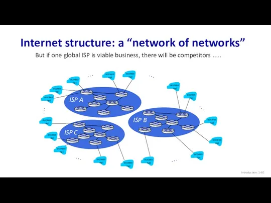
- 40. ISP A ISP C ISP B Internet structure: a “network of networks” Introduction: 1- But if
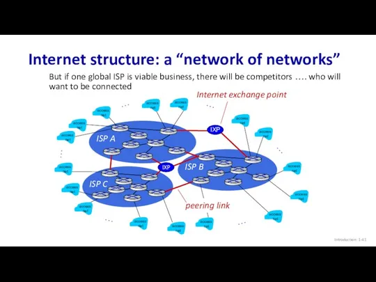
- 41. ISP A ISP C ISP B Internet structure: a “network of networks” Introduction: 1- But if
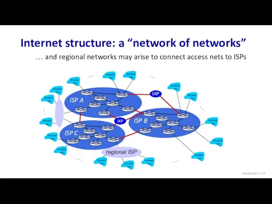
- 42. ISP A ISP C ISP B Internet structure: a “network of networks” Introduction: 1- … …
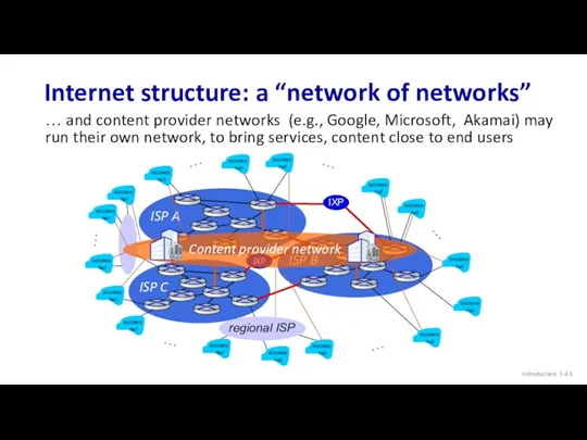
- 43. ISP A ISP C ISP B Internet structure: a “network of networks” Introduction: 1- … …
- 44. Internet structure: a “network of networks” Introduction: 1- Tier 1 ISP Tier 1 ISP Regional ISP
- 45. Topic 1: roadmap Introduction: 1- What is the Internet? What is a protocol? Network edge: hosts,
- 46. How do packet loss and delay occur? Introduction: 1- packets queue in router buffers packets queue,
- 47. Packet delay: four sources Introduction: 1- dproc: nodal processing check bit errors determine output link typically
- 48. Packet delay: four sources Introduction: 1- propagation nodal processing queueing dnodal = dproc + dqueue +
- 49. Caravan analogy Introduction: 1- cars “propagate” at 100 km/hr toll booth takes 12 sec to service
- 50. Caravan analogy Introduction: 1- ten-car caravan (aka 10-bit packet) 100 km 100 km suppose cars now
- 51. Packet queueing delay (revisited) Introduction: 1- R: link bandwidth (bps) L: packet length (bits) a: average
- 52. “Real” Internet delays and routes Introduction: 1- what do “real” Internet delay & loss look like?
- 53. Real Internet delays and routes Introduction: 1- 1 cs-gw (128.119.240.254) 1 ms 1 ms 2 ms
- 54. Packet loss Introduction: 1- queue (aka buffer) preceding link in buffer has finite capacity A B
- 55. Throughput Introduction: 1- throughput: rate (bits/time unit) at which bits are being sent from sender to
- 56. Throughput Introduction: 1- Rs Rs bits/sec Rs > Rc What is average end-end throughput?
- 57. Throughput: network scenario Introduction: 1- per-connection end-end throughput: min(Rc,Rs,R/10) in practice: Rc or Rs is often
- 58. Topic 1: roadmap Introduction: 1- What is the Internet? What is a protocol? Network edge: hosts,
- 59. Network security Introduction: 1- field of network security: how bad guys can attack computer networks how
- 60. Bad guys: malware Introduction: 1- malware can get in host from: virus: self-replicating infection by receiving/executing
- 61. Bad guys: denial of service Introduction: 1- Denial of Service (DoS): attackers make resources (server, bandwidth)
- 62. Bad guys: packet interception Introduction: 1- packet “sniffing”: broadcast media (shared Ethernet, wireless) promiscuous network interface
- 63. Bad guys: fake identity Introduction: 1- IP spoofing: send packet with false source address A B
- 64. Topic 1: roadmap Introduction: 1- What is the Internet? What is a protocol? Network edge: hosts,
- 65. Protocol “layers” and reference models Introduction: 1- Networks are complex, with many “pieces”: hosts routers links
- 66. Example: organization of air travel Introduction: 1- airline travel: a series of steps, involving many services
- 67. Example: organization of air travel Introduction: 1- ticket (purchase) baggage (check) gates (load) runway takeoff airplane
- 68. Why layering? Introduction: 1- dealing with complex systems: explicit structure allows identification, relationship of complex system’s
- 69. Internet protocol stack Introduction: 1- application: supporting network applications IMAP, SMTP, HTTP transport: process-process data transfer
- 70. Encapsulation Introduction: 1- source application transport network link physical segment datagram destination application transport network link
- 71. Topic 1: roadmap Introduction: 1- What is the Internet? What is a protocol? Network edge: hosts,
- 72. Internet history Introduction: 1- 1961: Kleinrock - queueing theory shows effectiveness of packet-switching 1964: Baran -
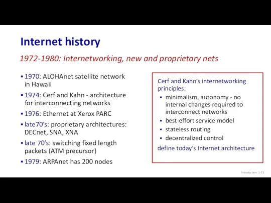
- 73. Internet history Introduction: 1- 1970: ALOHAnet satellite network in Hawaii 1974: Cerf and Kahn - architecture
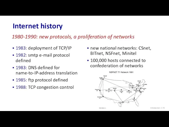
- 74. Internet history Introduction: 1- 1983: deployment of TCP/IP 1982: smtp e-mail protocol defined 1983: DNS defined
- 75. Internet history Introduction: 1- early 1990s: ARPAnet decommissioned 1991: NSF lifts restrictions on commercial use of
- 76. Internet history Introduction: 1- ~18B devices attached to Internet (2017) rise of smartphones (iPhone: 2007) aggressive
- 77. Topic 1: summary Introduction: 1- We’ve covered a “ton” of material! Internet overview what’s a protocol?
- 78. Additional Topic 1 slides Introduction: 1-
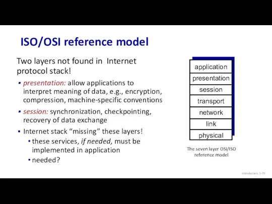
- 79. ISO/OSI reference model Introduction: 1- Two layers not found in Internet protocol stack! presentation: allow applications
- 81. Скачать презентацию
Course Overview
18 Lectures (15 lectures * 2 points = 30 points)
18
Course Overview
18 Lectures (15 lectures * 2 points = 30 points)
18
References
Kurose, James F. Computer networking : a top-down approach / James
References
Kurose, James F. Computer networking : a top-down approach / James
Study Tools
Lecture PPTs, Labs, Additional materials: https://jointvlab.ipt.pt/moodle/
Wireshark, Packet Tracer
Study Tools
Lecture PPTs, Labs, Additional materials: https://jointvlab.ipt.pt/moodle/
Wireshark, Packet Tracer
Topic 1: introduction
goal:
Get “feel,” “big picture,” introduction to terminology
more depth,
Topic 1: introduction
goal:
Get “feel,” “big picture,” introduction to terminology
more depth,
Internet
The Internet: a “nuts and bolts” view
Introduction: 1-
Internet
The Internet: a “nuts and bolts” view
Introduction: 1-
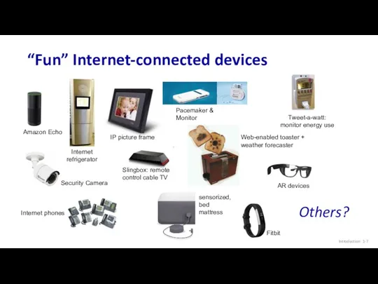
“Fun” Internet-connected devices
Introduction: 1-
IP picture frame
Web-enabled toaster +
weather forecaster
Internet phones
Slingbox: remote
control
“Fun” Internet-connected devices
Introduction: 1-
IP picture frame
Web-enabled toaster +
weather forecaster
Internet phones
Slingbox: remote
control
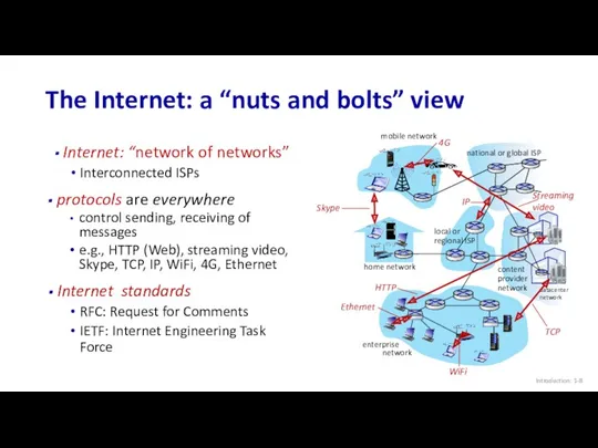
Internet: “network of networks”
Interconnected ISPs
The Internet: a “nuts and bolts” view
Introduction:
Internet: “network of networks”
Interconnected ISPs
The Internet: a “nuts and bolts” view
Introduction:
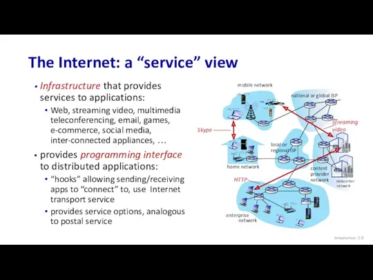
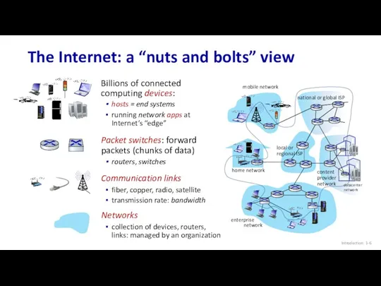
Infrastructure that provides services to applications:
Web, streaming video, multimedia teleconferencing, email,
Infrastructure that provides services to applications:
Web, streaming video, multimedia teleconferencing, email,
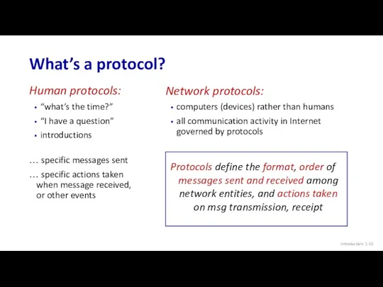
What’s a protocol?
Introduction: 1-
Human protocols:
“what’s the time?”
“I have a question”
introductions
… specific
What’s a protocol?
Introduction: 1-
Human protocols:
“what’s the time?”
“I have a question”
introductions
… specific
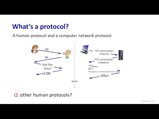
What’s a protocol?
Introduction: 1-
A human protocol and a computer network protocol:
Q:
What’s a protocol?
Introduction: 1-
A human protocol and a computer network protocol:
Q:

Topic 1: roadmap
Introduction: 1-
What is the Internet?
What is a protocol?
Network edge:
Topic 1: roadmap
Introduction: 1-
What is the Internet?
What is a protocol?
Network edge:
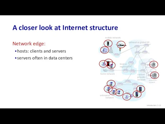
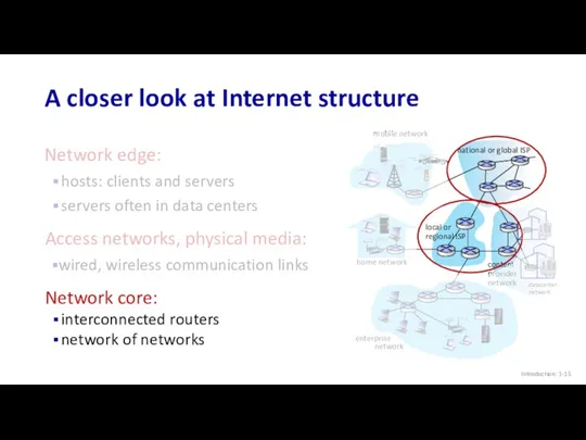
A closer look at Internet structure
Introduction: 1-
Network edge:
hosts: clients and servers
servers
A closer look at Internet structure
Introduction: 1-
Network edge:
hosts: clients and servers
servers
A closer look at Internet structure
Introduction: 1-
mobile network
home network
enterprise
network
national or
A closer look at Internet structure
Introduction: 1-
mobile network
home network
enterprise
network
national or
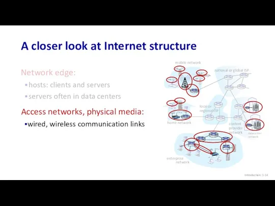
A closer look at Internet structure
Network edge:
hosts: clients and servers
servers often
A closer look at Internet structure
Network edge:
hosts: clients and servers
servers often
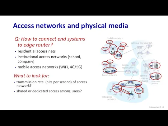
Access networks and physical media
Introduction: 1-
mobile network
home network
enterprise
network
national or global
Access networks and physical media
Introduction: 1-
mobile network
home network
enterprise
network
national or global
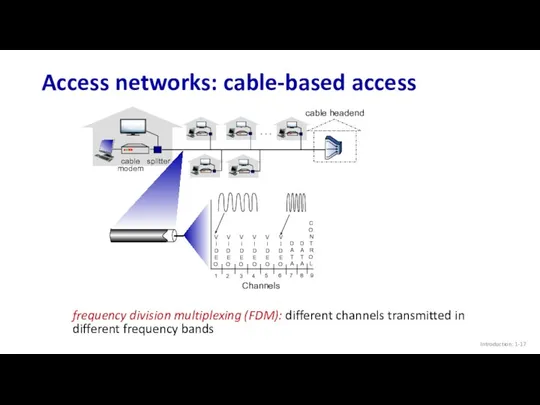
Access networks: cable-based access
Introduction: 1-
cable
modem
splitter
…
cable headend
frequency division multiplexing (FDM): different channels
Access networks: cable-based access
Introduction: 1-
cable
modem
splitter
…
cable headend
frequency division multiplexing (FDM): different channels
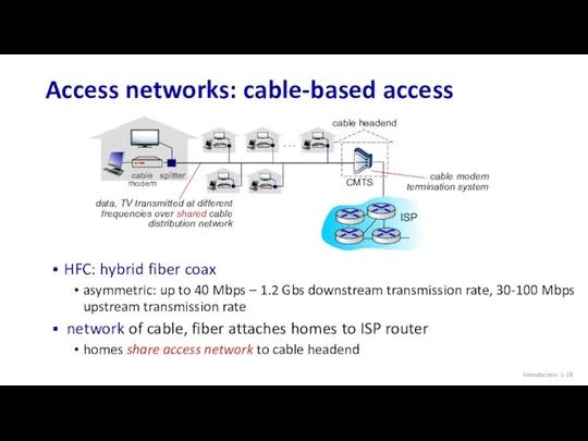
Access networks: cable-based access
Introduction: 1-
cable
modem
splitter
…
cable headend
HFC: hybrid fiber coax
asymmetric: up to
Access networks: cable-based access
Introduction: 1-
cable
modem
splitter
…
cable headend
HFC: hybrid fiber coax
asymmetric: up to
Introduction: 1-
Access networks: digital subscriber line (DSL)
central office
telephone
network
DSLAM
use existing telephone line
Introduction: 1-
Access networks: digital subscriber line (DSL)
central office
telephone
network
DSLAM
use existing telephone line
Introduction: 1-
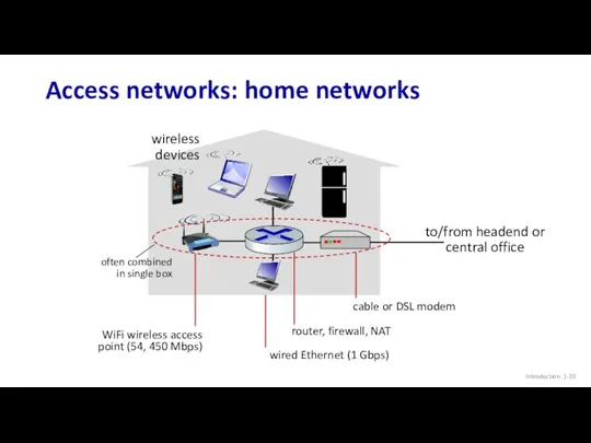
Access networks: home networks
to/from headend or central office
wireless
devices
Introduction: 1-
Access networks: home networks
to/from headend or central office
wireless
devices
Introduction: 1-
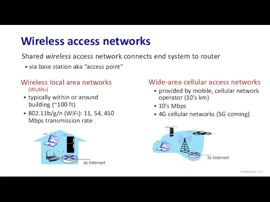
Wireless access networks
Shared wireless access network connects end system to
Introduction: 1-
Wireless access networks
Shared wireless access network connects end system to
Introduction: 1-
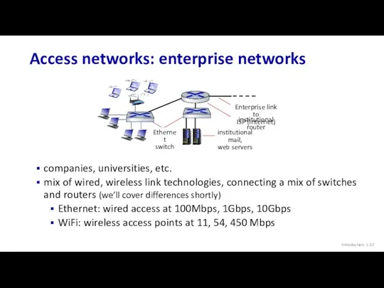
Access networks: enterprise networks
companies, universities, etc.
mix of wired, wireless link
Introduction: 1-
Access networks: enterprise networks
companies, universities, etc.
mix of wired, wireless link
Introduction: 1-
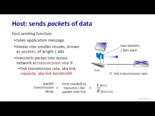
Host: sends packets of data
host sending function:
takes application message
breaks into
Introduction: 1-
Host: sends packets of data
host sending function:
takes application message
breaks into
Introduction: 1-
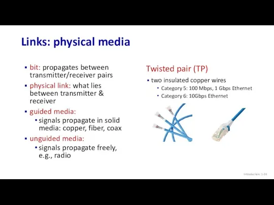
Links: physical media
bit: propagates between
transmitter/receiver pairs
physical link: what lies between
Introduction: 1-
Links: physical media
bit: propagates between
transmitter/receiver pairs
physical link: what lies between
Introduction: 1-
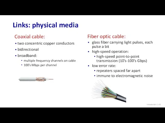
Links: physical media
Coaxial cable:
two concentric copper conductors
bidirectional
broadband:
multiple frequency channels on
Introduction: 1-
Links: physical media
Coaxial cable:
two concentric copper conductors
bidirectional
broadband:
multiple frequency channels on
Introduction: 1-
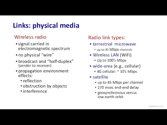
Links: physical media
Wireless radio
signal carried in electromagnetic spectrum
no physical “wire”
broadcast
Introduction: 1-
Links: physical media
Wireless radio
signal carried in electromagnetic spectrum
no physical “wire”
broadcast

Topic 1: roadmap
Introduction: 1-
What is the Internet?
What is a protocol?
Network edge:
Topic 1: roadmap
Introduction: 1-
What is the Internet?
What is a protocol?
Network edge:
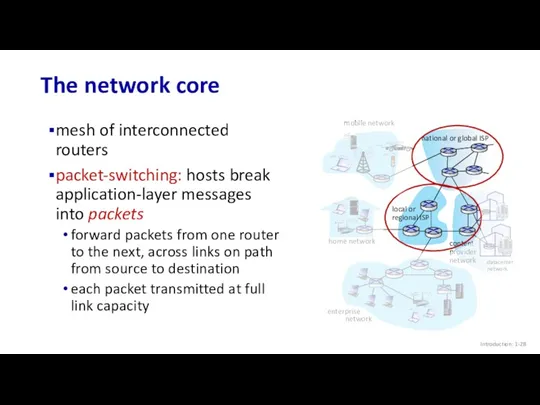
The network core
mesh of interconnected routers
packet-switching: hosts break application-layer messages into
The network core
mesh of interconnected routers
packet-switching: hosts break application-layer messages into
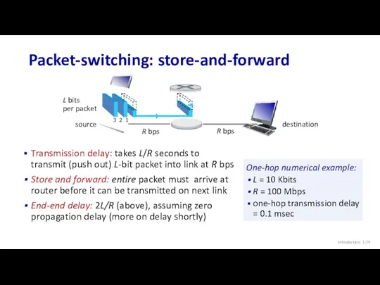
Packet-switching: store-and-forward
Transmission delay: takes L/R seconds to transmit (push out) L-bit
Packet-switching: store-and-forward
Transmission delay: takes L/R seconds to transmit (push out) L-bit
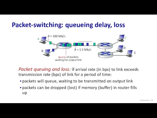
Packet-switching: queueing delay, loss
Packet queuing and loss: if arrival rate (in
Packet-switching: queueing delay, loss
Packet queuing and loss: if arrival rate (in
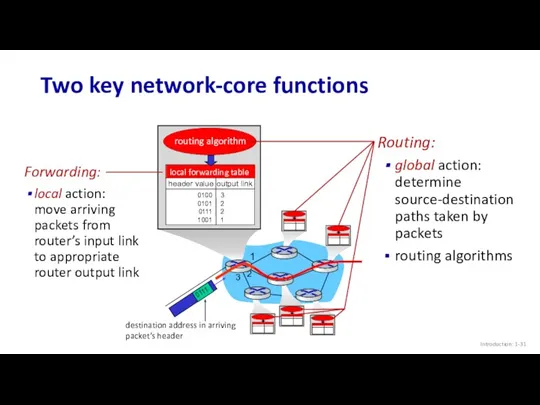
Two key network-core functions
Introduction: 1-
Forwarding:
local action: move arriving packets from
Two key network-core functions
Introduction: 1-
Forwarding:
local action: move arriving packets from
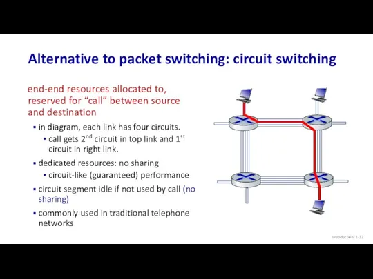
Alternative to packet switching: circuit switching
end-end resources allocated to, reserved for
Alternative to packet switching: circuit switching
end-end resources allocated to, reserved for
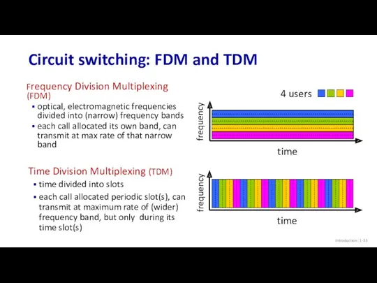
Circuit switching: FDM and TDM
Introduction: 1-
Frequency Division Multiplexing (FDM)
optical, electromagnetic frequencies
Circuit switching: FDM and TDM
Introduction: 1-
Frequency Division Multiplexing (FDM)
optical, electromagnetic frequencies
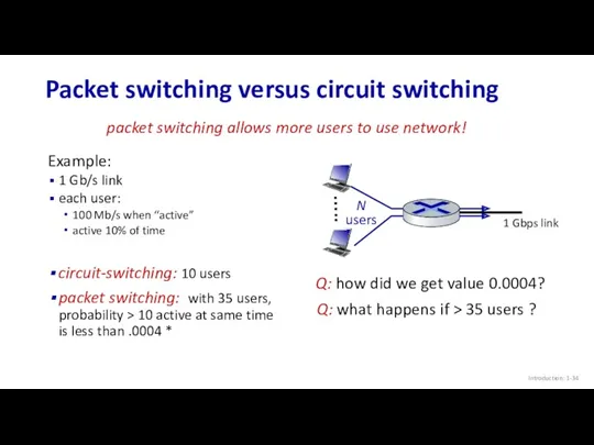
Packet switching versus circuit switching
Introduction: 1-
Example:
1 Gb/s link
each user:
100 Mb/s
Packet switching versus circuit switching
Introduction: 1-
Example:
1 Gb/s link
each user:
100 Mb/s
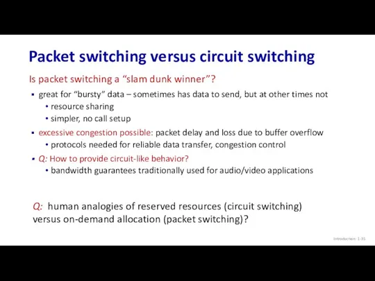
Packet switching versus circuit switching
Introduction: 1-
great for “bursty” data – sometimes
Packet switching versus circuit switching
Introduction: 1-
great for “bursty” data – sometimes
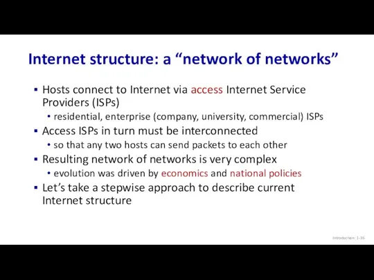
Internet structure: a “network of networks”
Hosts connect to Internet via access
Internet structure: a “network of networks”
Hosts connect to Internet via access
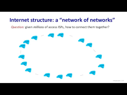
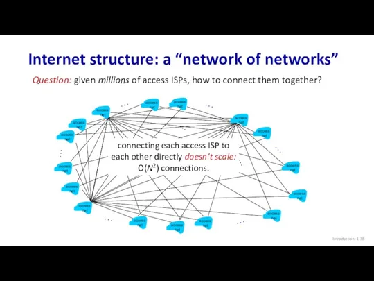
Internet structure: a “network of networks”
Introduction: 1-
Question: given millions of access
Internet structure: a “network of networks”
Introduction: 1-
Question: given millions of access
Internet structure: a “network of networks”
Introduction: 1-
Question: given millions of access
Internet structure: a “network of networks”
Introduction: 1-
Question: given millions of access
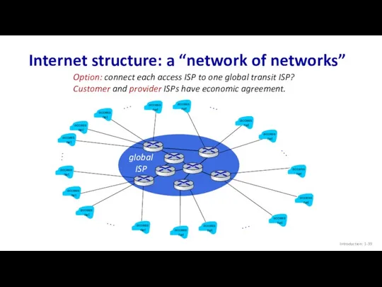
Internet structure: a “network of networks”
Introduction: 1-
Option: connect each access ISP
Internet structure: a “network of networks”
Introduction: 1-
Option: connect each access ISP
ISP A
ISP C
ISP B
Internet structure: a “network of networks”
Introduction: 1-
But if
ISP A
ISP C
ISP B
Internet structure: a “network of networks”
Introduction: 1-
But if
ISP A
ISP C
ISP B
Internet structure: a “network of networks”
Introduction: 1-
But if
ISP A
ISP C
ISP B
Internet structure: a “network of networks”
Introduction: 1-
But if
ISP A
ISP C
ISP B
Internet structure: a “network of networks”
Introduction: 1-
…
…
…
…
…
…
… and
ISP A
ISP C
ISP B
Internet structure: a “network of networks”
Introduction: 1-
…
…
…
…
…
…
… and
ISP A
ISP C
ISP B
Internet structure: a “network of networks”
Introduction: 1-
…
…
…
…
…
…
… and
ISP A
ISP C
ISP B
Internet structure: a “network of networks”
Introduction: 1-
…
…
…
…
…
…
… and
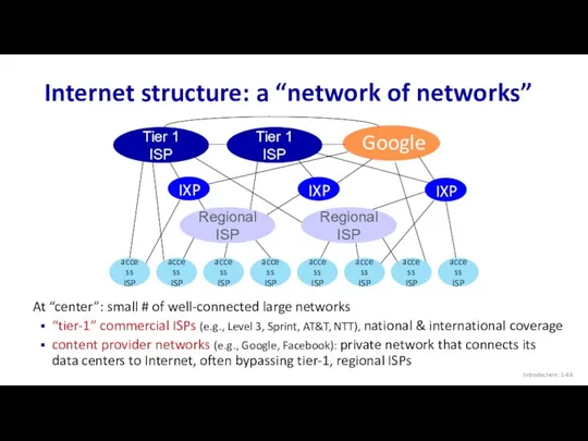
Internet structure: a “network of networks”
Introduction: 1-
Tier 1 ISP
Tier 1 ISP
Regional
Internet structure: a “network of networks”
Introduction: 1-
Tier 1 ISP
Tier 1 ISP
Regional
Topic 1: roadmap
Introduction: 1-
What is the Internet?
What is a protocol?
Network edge:
Topic 1: roadmap
Introduction: 1-
What is the Internet?
What is a protocol?
Network edge:
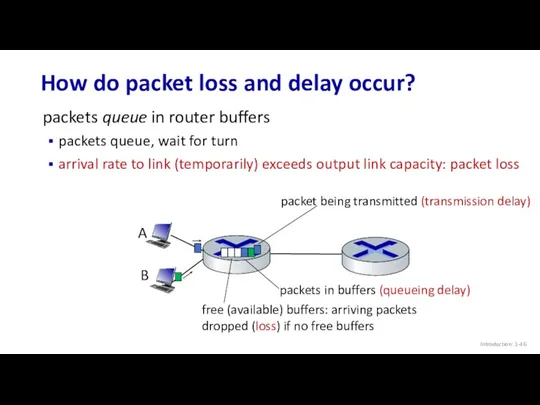
How do packet loss and delay occur?
Introduction: 1-
packets queue in router
How do packet loss and delay occur?
Introduction: 1-
packets queue in router
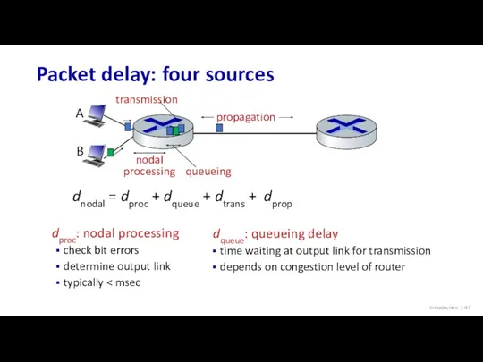
Packet delay: four sources
Introduction: 1-
dproc: nodal processing
check bit errors
determine output
Packet delay: four sources
Introduction: 1-
dproc: nodal processing
check bit errors
determine output
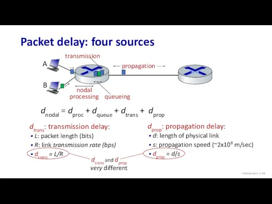
Packet delay: four sources
Introduction: 1-
propagation
nodal
processing
queueing
dnodal = dproc + dqueue + dtrans
Packet delay: four sources
Introduction: 1-
propagation
nodal
processing
queueing
dnodal = dproc + dqueue + dtrans
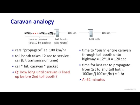
Caravan analogy
Introduction: 1-
cars “propagate” at 100 km/hr
toll booth takes 12 sec
Caravan analogy
Introduction: 1-
cars “propagate” at 100 km/hr
toll booth takes 12 sec
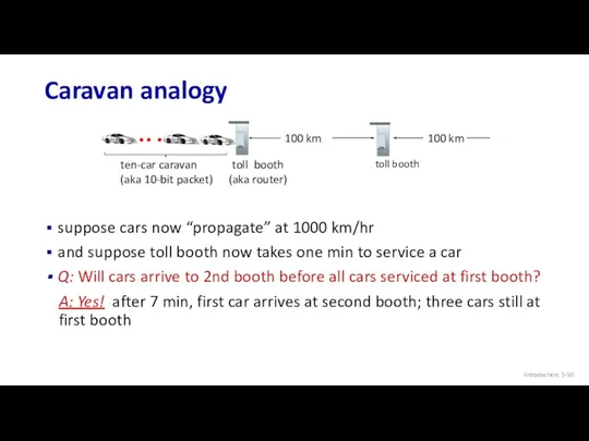
Caravan analogy
Introduction: 1-
ten-car caravan
(aka 10-bit packet)
100 km
100 km
suppose cars now “propagate”
Caravan analogy
Introduction: 1-
ten-car caravan
(aka 10-bit packet)
100 km
100 km
suppose cars now “propagate”
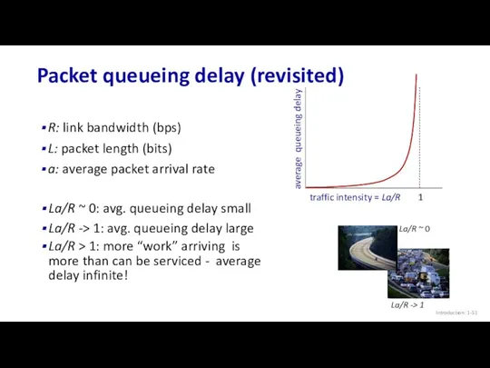
Packet queueing delay (revisited)
Introduction: 1-
R: link bandwidth (bps)
L: packet length (bits)
a:
Packet queueing delay (revisited)
Introduction: 1-
R: link bandwidth (bps)
L: packet length (bits)
a:
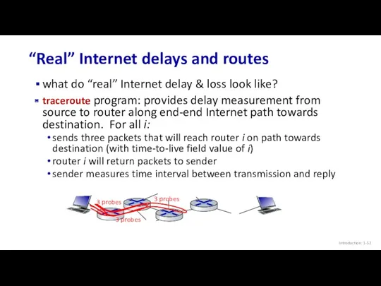
“Real” Internet delays and routes
Introduction: 1-
what do “real” Internet delay &
“Real” Internet delays and routes
Introduction: 1-
what do “real” Internet delay &
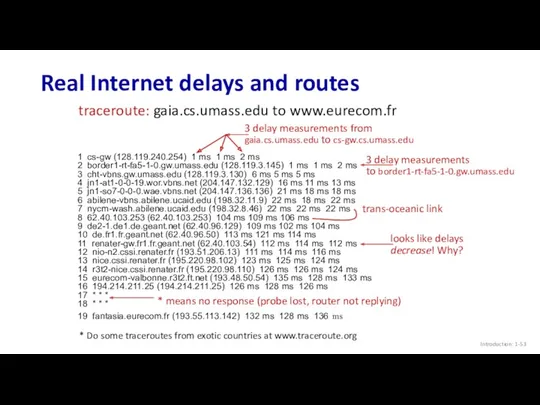
Real Internet delays and routes
Introduction: 1-
1 cs-gw (128.119.240.254) 1 ms 1
Real Internet delays and routes
Introduction: 1-
1 cs-gw (128.119.240.254) 1 ms 1
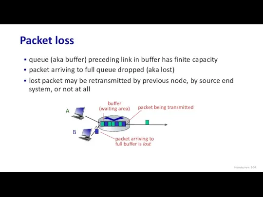
Packet loss
Introduction: 1-
queue (aka buffer) preceding link in buffer has finite
Packet loss
Introduction: 1-
queue (aka buffer) preceding link in buffer has finite
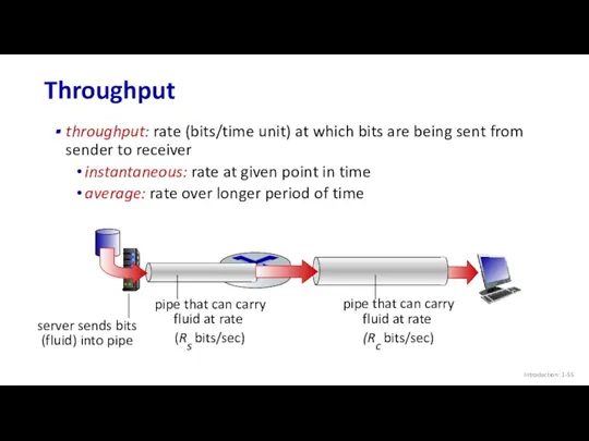
Throughput
Introduction: 1-
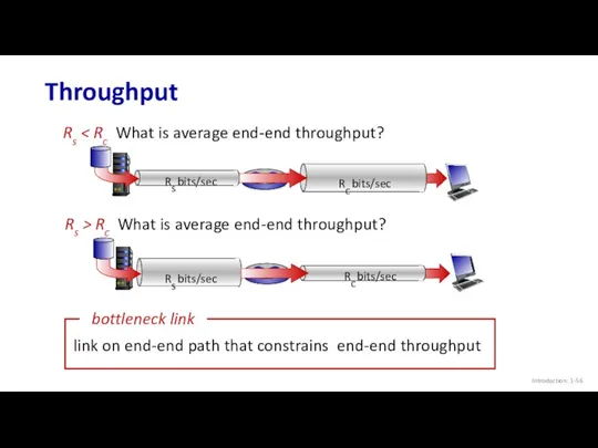
throughput: rate (bits/time unit) at which bits are being sent
Throughput
Introduction: 1-
throughput: rate (bits/time unit) at which bits are being sent
Throughput
Introduction: 1-
Rs < Rc What is average end-end throughput?
Rs bits/sec
Rs
Throughput
Introduction: 1-
Rs < Rc What is average end-end throughput?
Rs bits/sec
Rs
Throughput: network scenario
Introduction: 1-
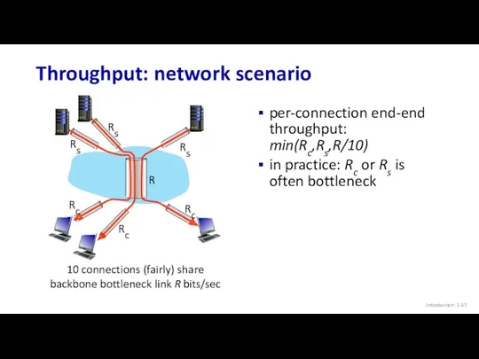
per-connection end-end throughput: min(Rc,Rs,R/10)
in practice: Rc or Rs
Throughput: network scenario
Introduction: 1-
per-connection end-end throughput: min(Rc,Rs,R/10)
in practice: Rc or Rs
Topic 1: roadmap
Introduction: 1-
What is the Internet?
What is a protocol?
Network edge:
Topic 1: roadmap
Introduction: 1-
What is the Internet?
What is a protocol?
Network edge:
Network security
Introduction: 1-
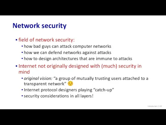
field of network security:
how bad guys can attack computer
Network security
Introduction: 1-
field of network security:
how bad guys can attack computer
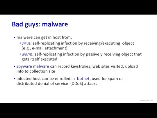
Bad guys: malware
Introduction: 1-
malware can get in host from:
virus: self-replicating
Bad guys: malware
Introduction: 1-
malware can get in host from:
virus: self-replicating
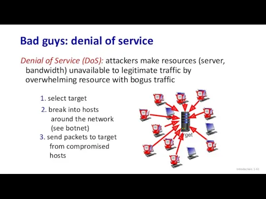
Bad guys: denial of service
Introduction: 1-
Denial of Service (DoS): attackers make
Bad guys: denial of service
Introduction: 1-
Denial of Service (DoS): attackers make
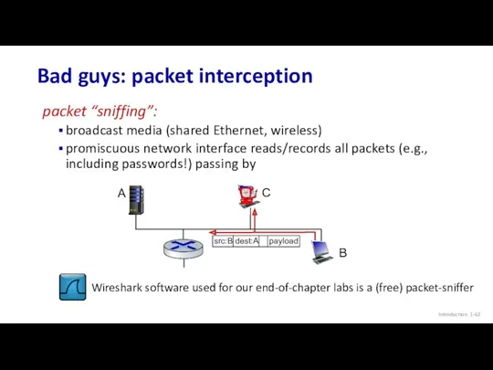
Bad guys: packet interception
Introduction: 1-
packet “sniffing”:
broadcast media (shared Ethernet, wireless)
promiscuous
Bad guys: packet interception
Introduction: 1-
packet “sniffing”:
broadcast media (shared Ethernet, wireless)
promiscuous
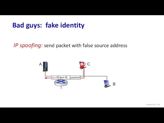
Bad guys: fake identity
Introduction: 1-
IP spoofing: send packet with false source
Bad guys: fake identity
Introduction: 1-
IP spoofing: send packet with false source

Topic 1: roadmap
Introduction: 1-
What is the Internet?
What is a protocol?
Network edge:
Topic 1: roadmap
Introduction: 1-
What is the Internet?
What is a protocol?
Network edge:
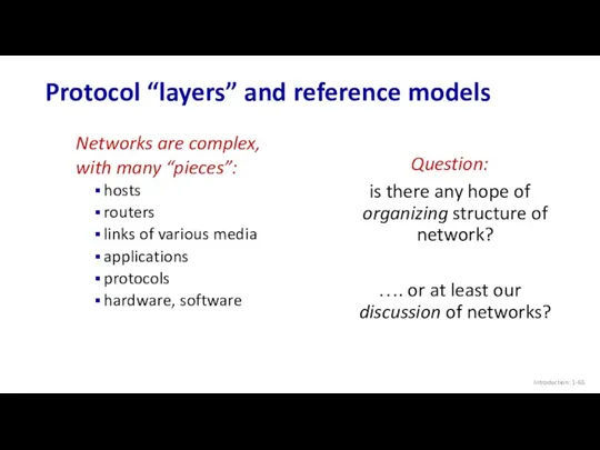
Protocol “layers” and reference models
Introduction: 1-
Networks are complex,
with many “pieces”:
hosts
routers
links of
Protocol “layers” and reference models
Introduction: 1-
Networks are complex,
with many “pieces”:
hosts
routers
links of
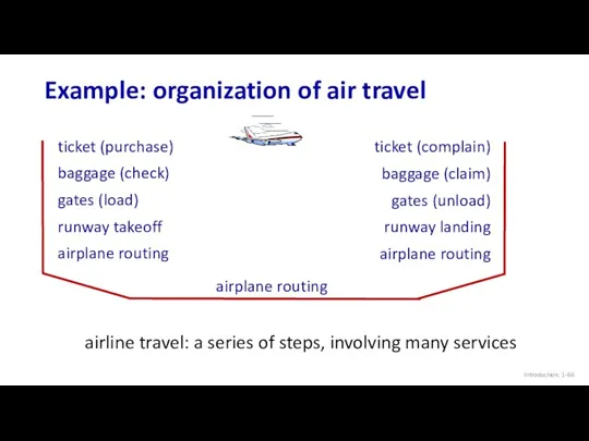
Example: organization of air travel
Introduction: 1-
airline travel: a series of steps,
Example: organization of air travel
Introduction: 1-
airline travel: a series of steps,
Example: organization of air travel
Introduction: 1-
ticket (purchase)
baggage (check)
gates (load)
runway takeoff
airplane routing
ticket
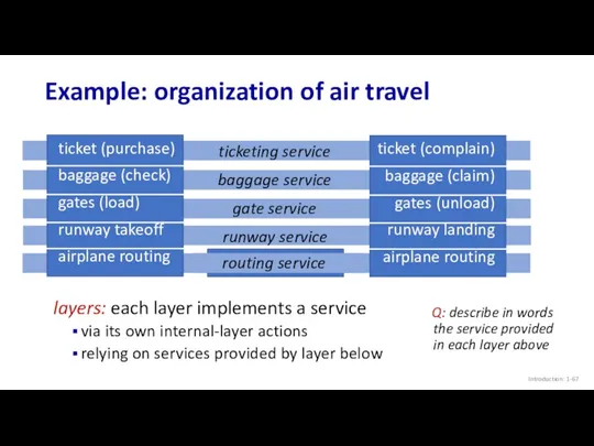
Example: organization of air travel
Introduction: 1-
ticket (purchase)
baggage (check)
gates (load)
runway takeoff
airplane routing
ticket
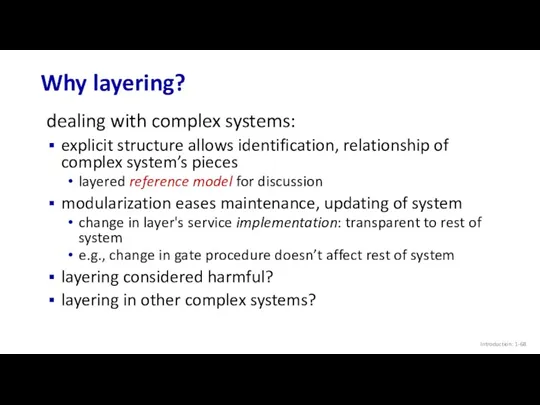
Why layering?
Introduction: 1-
dealing with complex systems:
explicit structure allows identification, relationship of
Why layering?
Introduction: 1-
dealing with complex systems:
explicit structure allows identification, relationship of
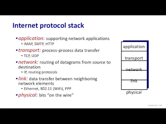
Internet protocol stack
Introduction: 1-
application: supporting network applications
IMAP, SMTP, HTTP
transport: process-process data
Internet protocol stack
Introduction: 1-
application: supporting network applications
IMAP, SMTP, HTTP
transport: process-process data
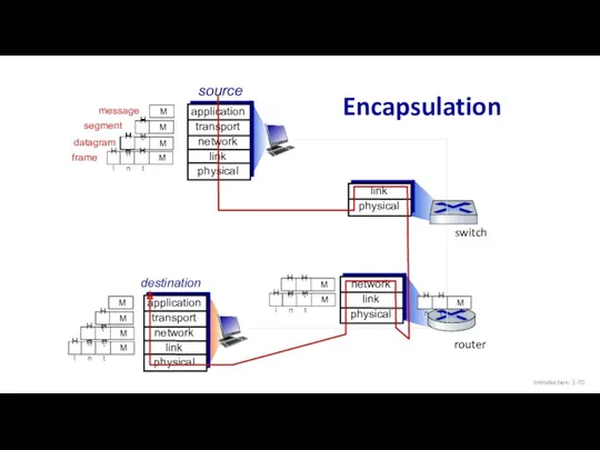
Encapsulation
Introduction: 1-
source
application
transport
network
link
physical
segment
datagram
destination
application
transport
network
link
physical
router
switch
message
frame
Encapsulation
Introduction: 1-
source
application
transport
network
link
physical
segment
datagram
destination
application
transport
network
link
physical
router
switch
message
frame

Topic 1: roadmap
Introduction: 1-
What is the Internet?
What is a protocol?
Network edge:
Topic 1: roadmap
Introduction: 1-
What is the Internet?
What is a protocol?
Network edge:
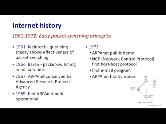
Internet history
Introduction: 1-
1961: Kleinrock - queueing theory shows effectiveness of packet-switching
1964:
Internet history
Introduction: 1-
1961: Kleinrock - queueing theory shows effectiveness of packet-switching
1964:
Internet history
Introduction: 1-
1970: ALOHAnet satellite network in Hawaii
1974: Cerf and Kahn
Internet history
Introduction: 1-
1970: ALOHAnet satellite network in Hawaii
1974: Cerf and Kahn
Internet history
Introduction: 1-
1983: deployment of TCP/IP
1982: smtp e-mail protocol defined
1983:
Internet history
Introduction: 1-
1983: deployment of TCP/IP
1982: smtp e-mail protocol defined
1983:
Internet history
Introduction: 1-
early 1990s: ARPAnet decommissioned
1991: NSF lifts restrictions on commercial
Internet history
Introduction: 1-
early 1990s: ARPAnet decommissioned
1991: NSF lifts restrictions on commercial
Internet history
Introduction: 1-
~18B devices attached to Internet (2017)
rise of smartphones (iPhone:
Internet history
Introduction: 1-
~18B devices attached to Internet (2017)
rise of smartphones (iPhone:
Topic 1: summary
Introduction: 1-
We’ve covered a “ton” of material!
Internet overview
what’s a
Topic 1: summary
Introduction: 1-
We’ve covered a “ton” of material!
Internet overview
what’s a

Additional Topic 1 slides
Introduction: 1-
Additional Topic 1 slides
Introduction: 1-
ISO/OSI reference model
Introduction: 1-
Two layers not found in Internet protocol stack!
presentation:
ISO/OSI reference model
Introduction: 1-
Two layers not found in Internet protocol stack!
presentation:
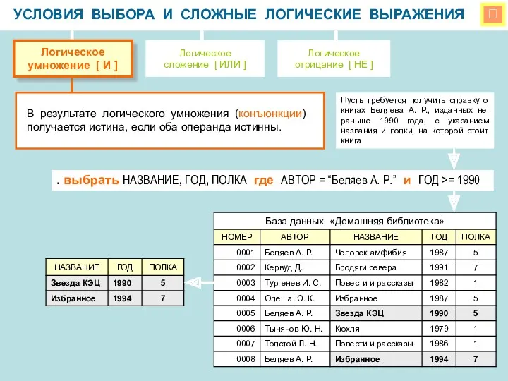 Условия выбора и сложные логические выражения
 Введение в Django
 Создание и управление базой данных в СУБД Access
 Объектно-ориентированное программирование
 презентация
 Корректировки по сайту NLS Kazakhtan
 Искусственный интеллект и ЭВМ
 Компьютерная графика. (Лекция 1)
 загрузка торрента
 Базы данных. Введение
 Организация ветвления в Python. Алгоритмы и программирование, язык Python. 10 класс
 Язык программирования Pascal Массивы
 Носители информации
 Принципы объектно-ориентированного проектирования
 Компьютерная графика
 Партнерская программа касса24
 Новые печатные формы диплома и приложения к диплому с формированием QR кода в 1С:Колледж и 1С:Колледж ПРОФ
 Информационные модели на графах. Пути в графах
 Захист даних у сфері електронної комерції
 Теоретические основы проектирования информационных систем
 Программирование на языке Паскаль
 Теория информации
 Учет заявок на участие в фестивале
 Инфознайка. Всероссийская игра-конкурс по информатике
 Общие сведения об информатике и информации
 Основы логики и логические основы компьютера
 Правила безопасности в Интернете. Персональная информация
 Область застосування CSS. Способи використання в HTML документі