- Easy access to embedded at SIM800(R)

Содержание
- 2. Content 1. Embedded AT Core Conception 2. Embedded AT Functions 3. Example: ADC Detection
- 3. 1. Embedded AT Core Conception 1.1 Embedded AT Core Conception 1.2 Think from MCU Side 1.3
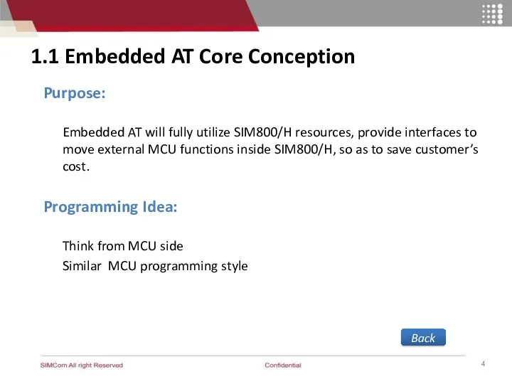
- 4. 1.1 Embedded AT Core Conception Purpose: Embedded AT will fully utilize SIM800/H resources, provide interfaces to
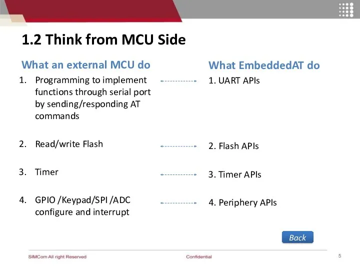
- 5. 1.2 Think from MCU Side What an external MCU do Programming to implement functions through serial
- 6. MCU Framework void main(void) { Init Hardware(); Init Variable(); Start Timer(); while(TRUE) { Progress ModemData(); Progress
- 7. 2. Embedded AT Functions 2.1 Send and Receive AT Command 2.2 FLASH Operation 2.3 Timer 2.4
- 8. 2.1 Send and Receive AT Command SIM800 MCU Send via UART SIM800 Core APP SIM800 MCU
- 9. Example: Send “AT+CNETLIGHT=0”when powering on and get response. void app_main(void) { APP_InitRegions(); APP_init_clib(); … Eat_modem_write(“AT+CNETLIGHT=0\r”,strlen(“AT+CNETLIGHT=0\r”)); while(TRUE)
- 10. 2.2 FLASH Operation 2.2.1 Read data 2.2.2 Write Data 2.2.3 Other Flash APIs Back
- 11. 2.2.1 Read Data Step1: Define a global array u8 Buffer[8*1024] Step2: Read flash data from flash
- 12. 2.2.2 Write Data Step1: Define a global array u8 Buffer[8*1024] Step2: Fill the data to be
- 13. 2.2.3 Other Flash APIs 1. Delete flash data from related address eat_bool eat_flash_erase(flash_addr, len) 2. Acquire
- 14. 2.3 Timer 2.3.1 Start / Stop Timer 2.3.2 Timer EVENT 2.3.3 Get System time Back
- 15. 2.3.2 Start / Stop Timer Start or stop timer Soft timer: Start timer: eat_timer_start(timer_id, expire_ms); Stop
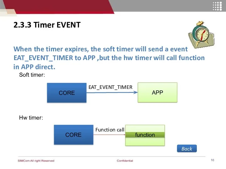
- 16. APP 2.3.3 Timer EVENT When the timer expires, the soft timer will send a event EAT_EVENT_TIMER
- 17. 2.3.4 Get System Time 1. EatRtc_st structure typedef struct { unsigned char sec; /* [0, 59]
- 18. 2.4 Configuration and Usage of GPIO 2.4.1 Pins for GPIO 2.4.2 Configure PIN to GPO 2.4.3
- 19. 2.4.1 Pins for GPIO Available GPIOs in SIM800H typedef enum FlPinNameTag { EAT_PIN3_GPIO1, EAT_PIN4_STATUS, … EAT_PIN74_SCL,
- 20. 2.4.2 Configure PIN to GPIO and output mode Step1: Configure the target PIN as GPIO eat_bool
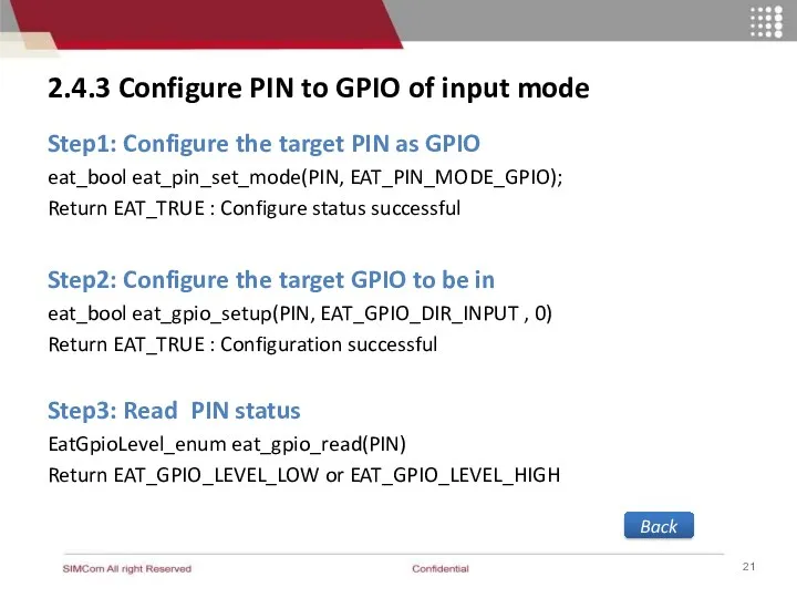
- 21. 2.4.3 Configure PIN to GPIO of input mode Step1: Configure the target PIN as GPIO eat_bool
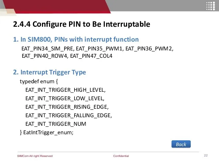
- 22. 2.4.4 Configure PIN to Be Interruptable 1. In SIM800, PINs with interrupt function EAT_PIN34_SIM_PRE, EAT_PIN35_PWM1, EAT_PIN36_PWM2,
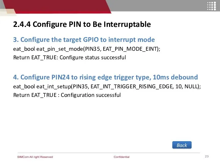
- 23. 2.4.4 Configure PIN to Be Interruptable 3. Configure the target GPIO to interrupt mode eat_bool eat_pin_set_mode(PIN35,
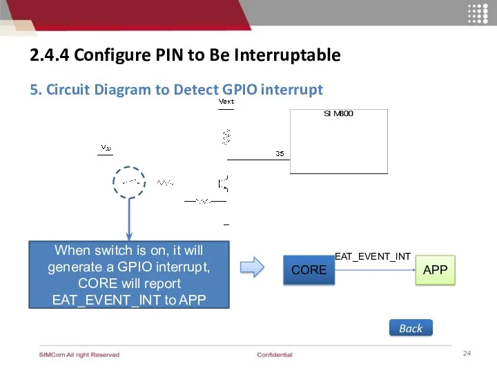
- 24. 2.4.4 Configure PIN to Be Interruptable 5. Circuit Diagram to Detect GPIO interrupt When switch is
- 25. 2.4.5 Configure PIN for Keypad 1. Initializes keypad pins eat_bool eat_pin_set_mode(pin, EAT_PIN_MODE_KEY); Note: If any of
- 26. 2.4.5 Configure PIN for Keypad 2. Following GPIOs can be configured to keypad in SIM800: EAT_PIN40_ROW4~
- 27. 2.4.5 Configure PIN for Keypad 3. EAT_EVENT_KEY report to APP 4. The values of each key(key_val)
- 28. 2.5 SPI Interface Configure SPI bus, set according to actual situation eat_bool eat_spi_init(clk, wire, bit, enable_SDI,
- 29. 2.6 UART operation 2.6.1 UART 2.6.2 Configure UART as AT port or DEBUG port 2.6.3 Configure
- 30. 2.6.1 UART Back 2 UART 1 USB (usb2serial)
- 31. 2.6.2 Configure UART as AT port or DEBUG port 1. AT port eat_bool eat_uart_set_at_port(port) 2. Debug
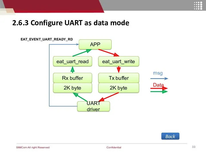
- 32. 2.6.3 Configure UART as data mode 1. Open the UART eat_bool eat_uart_open(UART) If EAT_FALSE given, that
- 33. 2.6.3 Configure UART as data mode Back APP eat_uart_read UART driver Tx buffer Rx buffer eat_uart_write
- 34. 3. ADC Detection Example 3.1 Function Description 3.2 Design Flow 3.3 Sample Code Back
- 35. 3.1 Function Description Task Example: To detect the voltage of ADC pin of SIM800 module periodically.
- 36. 3.2 Design Flow Init parameter Function call Core EAT_EVENT_ADC Query voltage by api Get Event APP
- 38. Скачать презентацию
Content
1. Embedded AT Core Conception
2. Embedded AT Functions
3. Example: ADC
Content
1. Embedded AT Core Conception
2. Embedded AT Functions
3. Example: ADC
1. Embedded AT Core Conception
1.1 Embedded AT Core Conception
1.2 Think from
1. Embedded AT Core Conception
1.1 Embedded AT Core Conception
1.2 Think from
1.1 Embedded AT Core Conception
Purpose:
Embedded AT will fully utilize SIM800/H
1.1 Embedded AT Core Conception
Purpose:
Embedded AT will fully utilize SIM800/H
1.2 Think from MCU Side
What an external MCU do
Programming to implement
1.2 Think from MCU Side
What an external MCU do
Programming to implement
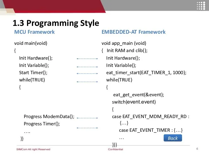
MCU Framework
void main(void)
{
Init Hardware();
Init Variable();
Start Timer();
while(TRUE)
MCU Framework
void main(void)
{
Init Hardware();
Init Variable();
Start Timer();
while(TRUE)
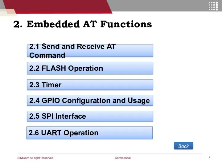
2. Embedded AT Functions
2.1 Send and Receive AT Command
2.2 FLASH
2. Embedded AT Functions
2.1 Send and Receive AT Command
2.2 FLASH
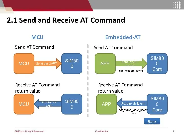
2.1 Send and Receive AT Command
SIM800
MCU
Send via UART
SIM800
Core
APP
SIM800
MCU
SIM800
Core
APP
Send AT Command
Receive
2.1 Send and Receive AT Command
SIM800
MCU
Send via UART
SIM800
Core
APP
SIM800
MCU
SIM800
Core
APP
Send AT Command
Receive
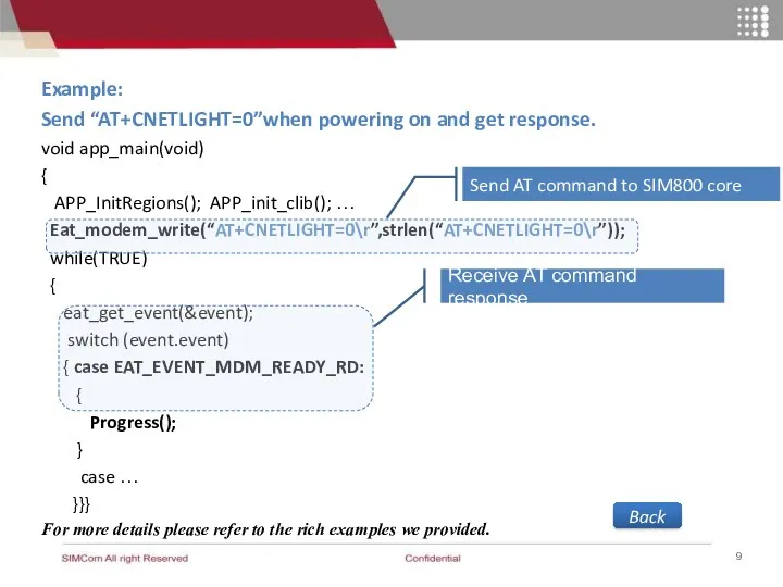
Example:
Send “AT+CNETLIGHT=0”when powering on and get response.
void app_main(void)
{
APP_InitRegions();
Example:
Send “AT+CNETLIGHT=0”when powering on and get response.
void app_main(void)
{
APP_InitRegions();
2.2 FLASH Operation
2.2.1 Read data
2.2.2 Write Data
2.2.3 Other Flash APIs
Back
2.2 FLASH Operation
2.2.1 Read data
2.2.2 Write Data
2.2.3 Other Flash APIs
Back
![2.2.1 Read Data Step1: Define a global array u8 Buffer[8*1024]](/_ipx/f_webp&q_80&fit_contain&s_1440x1080/imagesDir/jpg/370072/slide-10.jpg)
2.2.1 Read Data
Step1: Define a global array
u8 Buffer[8*1024]
Step2: Read flash data
2.2.1 Read Data
Step1: Define a global array
u8 Buffer[8*1024]
Step2: Read flash data
![2.2.2 Write Data Step1: Define a global array u8 Buffer[8*1024]](/_ipx/f_webp&q_80&fit_contain&s_1440x1080/imagesDir/jpg/370072/slide-11.jpg)
2.2.2 Write Data
Step1: Define a global array
u8 Buffer[8*1024]
Step2: Fill the data
2.2.2 Write Data
Step1: Define a global array
u8 Buffer[8*1024]
Step2: Fill the data
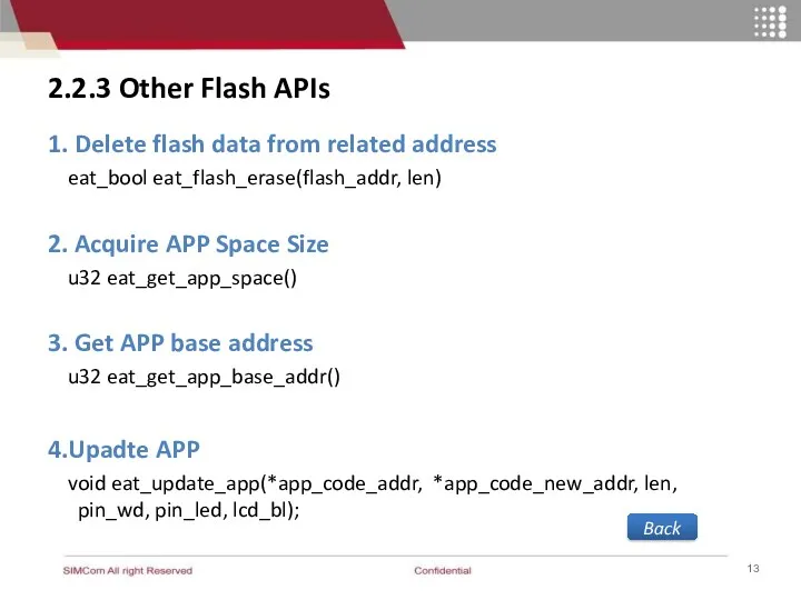
2.2.3 Other Flash APIs
1. Delete flash data from related address
eat_bool
2.2.3 Other Flash APIs
1. Delete flash data from related address
eat_bool
2.3 Timer
2.3.1 Start / Stop Timer
2.3.2 Timer EVENT
2.3.3 Get System time
Back
2.3 Timer
2.3.1 Start / Stop Timer
2.3.2 Timer EVENT
2.3.3 Get System time
Back
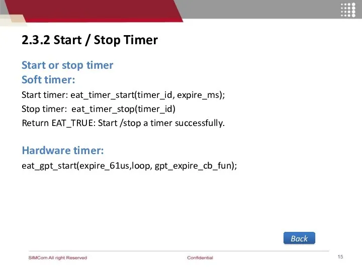
2.3.2 Start / Stop Timer
Start or stop timer
Soft timer:
Start timer:
2.3.2 Start / Stop Timer
Start or stop timer
Soft timer:
Start timer:
APP
2.3.3 Timer EVENT
When the timer expires, the soft timer will send
APP
2.3.3 Timer EVENT
When the timer expires, the soft timer will send
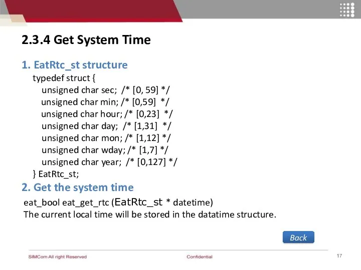
2.3.4 Get System Time
1. EatRtc_st structure
typedef struct {
unsigned char
2.3.4 Get System Time
1. EatRtc_st structure
typedef struct {
unsigned char
2.4 Configuration and Usage of GPIO
2.4.1 Pins for GPIO
2.4.2 Configure PIN
2.4 Configuration and Usage of GPIO
2.4.1 Pins for GPIO
2.4.2 Configure PIN
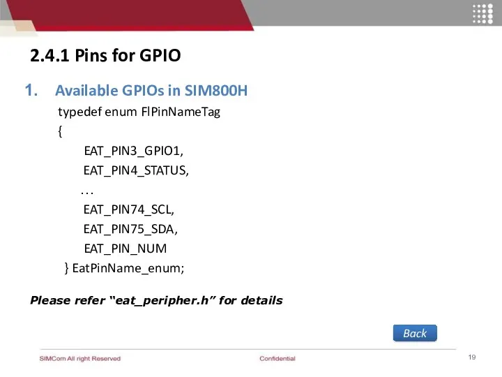
2.4.1 Pins for GPIO
Available GPIOs in SIM800H
typedef enum FlPinNameTag
{
2.4.1 Pins for GPIO
Available GPIOs in SIM800H
typedef enum FlPinNameTag
{

2.4.2 Configure PIN to GPIO and output mode
Step1: Configure the
2.4.2 Configure PIN to GPIO and output mode
Step1: Configure the
2.4.3 Configure PIN to GPIO of input mode
Step1: Configure the
2.4.3 Configure PIN to GPIO of input mode
Step1: Configure the
2.4.4 Configure PIN to Be Interruptable
1. In SIM800, PINs with interrupt
2.4.4 Configure PIN to Be Interruptable
1. In SIM800, PINs with interrupt
2.4.4 Configure PIN to Be Interruptable
3. Configure the target GPIO to
2.4.4 Configure PIN to Be Interruptable
3. Configure the target GPIO to
2.4.4 Configure PIN to Be Interruptable
5. Circuit Diagram to Detect GPIO
2.4.4 Configure PIN to Be Interruptable
5. Circuit Diagram to Detect GPIO
2.4.5 Configure PIN for Keypad
1. Initializes keypad pins
eat_bool eat_pin_set_mode(pin, EAT_PIN_MODE_KEY);
Note:
If
2.4.5 Configure PIN for Keypad
1. Initializes keypad pins
eat_bool eat_pin_set_mode(pin, EAT_PIN_MODE_KEY);
Note:
If
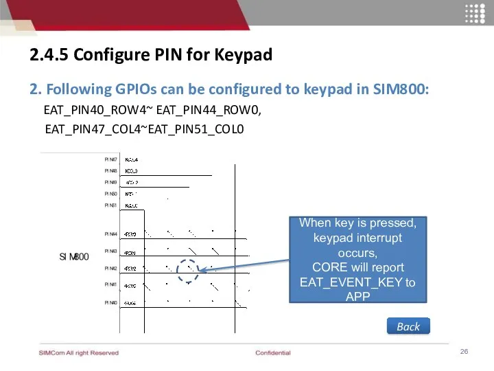
2.4.5 Configure PIN for Keypad
2. Following GPIOs can be configured to
2.4.5 Configure PIN for Keypad
2. Following GPIOs can be configured to
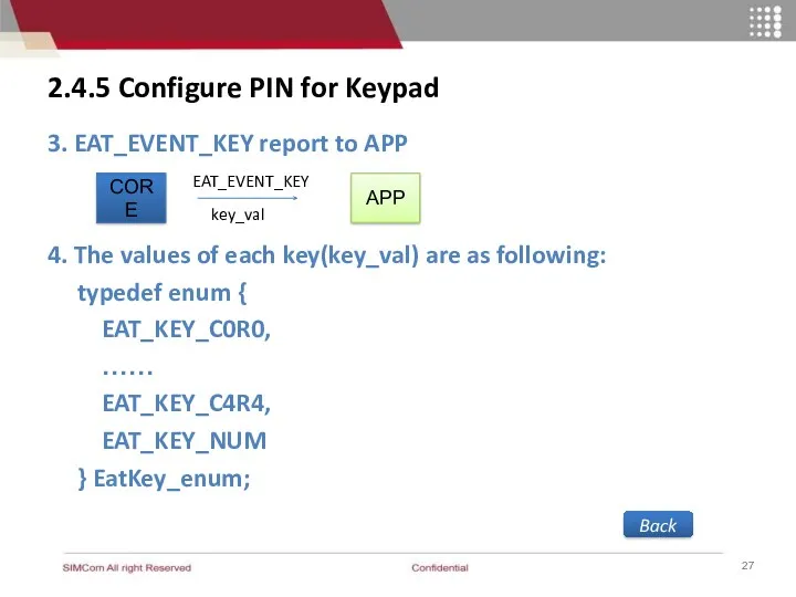
2.4.5 Configure PIN for Keypad
3. EAT_EVENT_KEY report to APP
4. The values
2.4.5 Configure PIN for Keypad
3. EAT_EVENT_KEY report to APP
4. The values
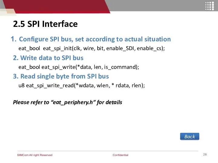
2.5 SPI Interface
Configure SPI bus, set according to actual situation
eat_bool
2.5 SPI Interface
Configure SPI bus, set according to actual situation
eat_bool
2.6 UART operation
2.6.1 UART
2.6.2 Configure UART as AT port or
2.6 UART operation
2.6.1 UART
2.6.2 Configure UART as AT port or
2.6.1 UART
Back
2 UART
1 USB (usb2serial)
2.6.1 UART
Back
2 UART
1 USB (usb2serial)
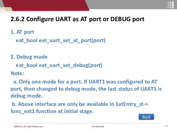
2.6.2 Configure UART as AT port or DEBUG port
1. AT port
2.6.2 Configure UART as AT port or DEBUG port
1. AT port
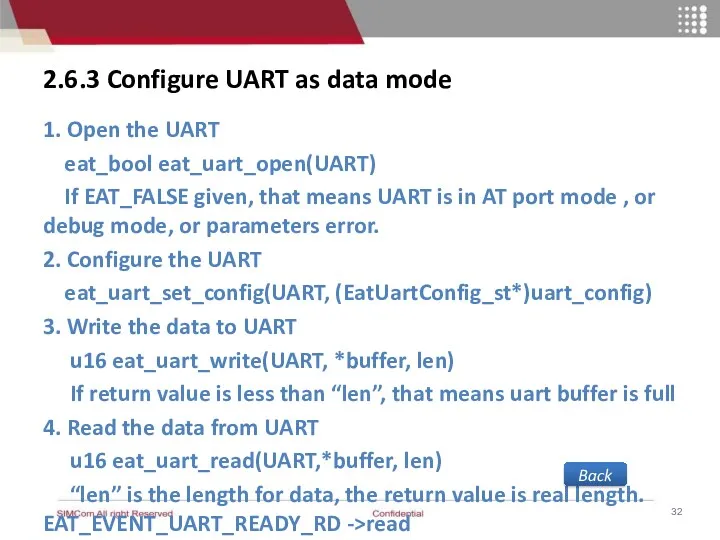
2.6.3 Configure UART as data mode
1. Open the UART
eat_bool eat_uart_open(UART)
2.6.3 Configure UART as data mode
1. Open the UART
eat_bool eat_uart_open(UART)
2.6.3 Configure UART as data mode
Back
APP
eat_uart_read
UART driver
Tx buffer
Rx buffer
eat_uart_write
2K byte
2K byte
msg
Data
EAT_EVENT_UART_READY_RD
2.6.3 Configure UART as data mode
Back
APP
eat_uart_read
UART driver
Tx buffer
Rx buffer
eat_uart_write
2K byte
2K byte
msg
Data
EAT_EVENT_UART_READY_RD
3. ADC Detection Example
3.1 Function Description
3.2 Design Flow
3.3 Sample Code
Back
3. ADC Detection Example
3.1 Function Description
3.2 Design Flow
3.3 Sample Code
Back
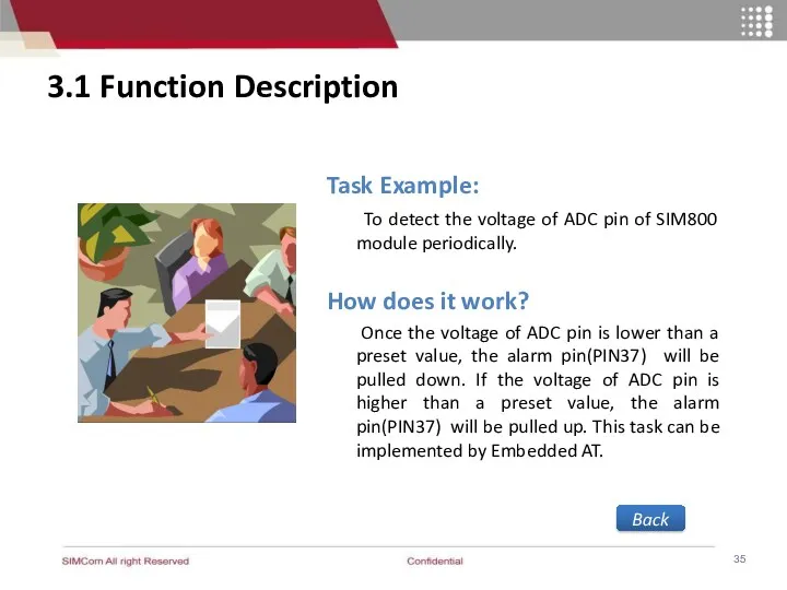
3.1 Function Description
Task Example:
To detect the voltage of ADC pin
3.1 Function Description
Task Example:
To detect the voltage of ADC pin
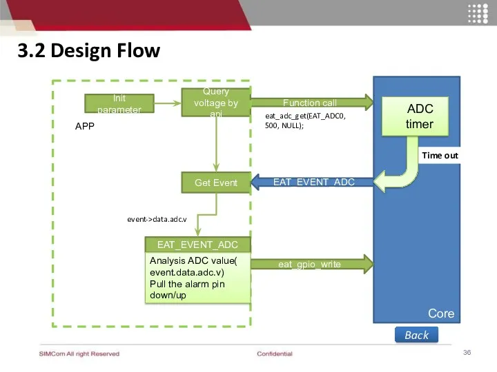
3.2 Design Flow
Init parameter
Function call
Core
EAT_EVENT_ADC
Query voltage by api
Get Event
APP
eat_gpio_write
EAT_EVENT_ADC
Analysis ADC value(
3.2 Design Flow
Init parameter
Function call
Core
EAT_EVENT_ADC
Query voltage by api
Get Event
APP
eat_gpio_write
EAT_EVENT_ADC
Analysis ADC value(
 Статистическое кодирование сообщений
 Презентация урока по теме:Алгоритмы 9 класс
 Система электронного документооборота TESSA
 Разработка и создание базы данных для организации сервисных услуг в гостиницах различного уровня
 Основы объективно-ориентированного программирования в среде Lazarus. Повторение
 ntroduction to Software-defined Networking (SDN)
 Разработка компьютерной видеоигры
 Метод сортировки вставками
 Сортировка и фильтрация данных
 Модели представления знаний. Семантическая модель
 Информационные технологии
 Работа в основных социальных сетях
 Инструкция по Зарплатному проекту в ИБ ПСБ Бизнес
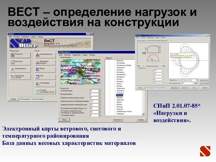 ВЕСТ – определение нагрузок и воздействия на конструкции
 Основы российской государственности на тему Кибербезопасность
 Поиск информации
 Разработка конфигурации Склад стройматериалов
 Разработчик программного обеспечения iXart . Массовая, многопользовательская, ролевая online-игра Моя жизнь
 Линии связи сетей ЭВМ. Занятие 13
 Интерфейсы. Лекция №8
 Базовые сетевые характеристики: производительность, надежность и характеристики сети поставщика услуг
 Немного фактов о scratch и немного о языках программирования
 Cascading style sheets
 Windows Movie Maker
 Чем мы можем дорабатывать Revit? DisignScript, Python C#. Что такое Dynamo?
 Робота з клавіатурою
 Базовое расписание проекта работ
 Социальная информатика: предмет и задачи курса