ENG 100 Introduction to Engineering. CAD-LAB-2: Surface Design – Rhino Automation – Solid Modeling (CSG & B-Rep) презентация
- ENG 100 Introduction to Engineering. CAD-LAB-2: Surface Design – Rhino Automation – Solid Modeling (CSG & B-Rep)

Содержание
- 2. Contents Nazarbayev University, ENG 100 - Introduction to Engineering 2. Universal Joint 3. Shaft Assembly 4.
- 3. CSG Constructive solid geometry (CSG) is an approach followed in solid modeling. Constructive solid geometry allows
- 4. B-rep The second and most popular approach in solid modeling and computer-aided design, is the boundary
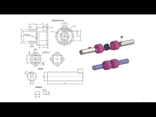
- 5. Universal Joint (Universal coupling, U-Joint, Cardan Joint) Nazarbayev University, ENG 100 - Introduction to Engineering
- 6. Nazarbayev University, ENG 100 - Introduction to Engineering
- 7. 3d modeling of simple U-joint Description: Create the 3d model of the U-joint shown in previous
- 8. Modeling steps: Step 1 Launch Rhino using mm as units and a tolerance of 1 micron
- 9. Modeling steps: Step 2 Create the second shaft by mirroring the first one (remember to set
- 10. Modeling steps: Step 3 Make “sphere” layer the current layer Create a sphere with radius 9
- 11. Modeling steps: Step 4 Make “joint” layer the current layer Create a cylinder with diameter 30
- 12. Modeling steps: Step 5 On the sphere side of the joint, create the two holding brackets:
- 13. Modeling steps: Final Step The resulting model should like the first picture besides Create a copy
- 14. Shaft Assembly example Nazarbayev University, ENG 100 - Introduction to Engineering Shaft Wedge Flange Wheel Collar
- 15. Nazarbayev University, ENG 100 - Introduction to Engineering
- 16. Modeling Steps: Step 1 Launch Rhino using mm as units and a tolerance of 1 micron
- 17. Step 1 Result Nazarbayev University, ENG 100 - Introduction to Engineering Hints: Use the subcommand “from”
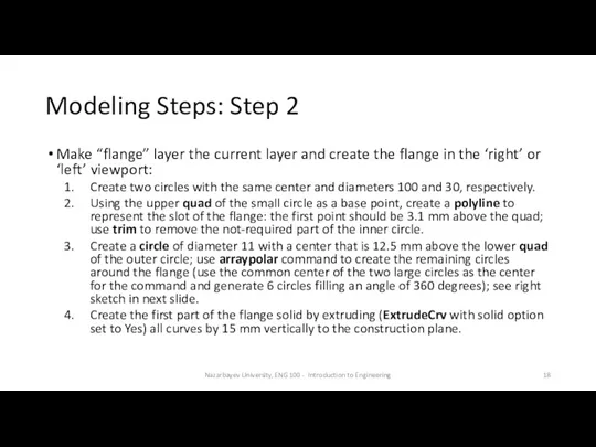
- 18. Modeling Steps: Step 2 Make “flange” layer the current layer and create the flange in the
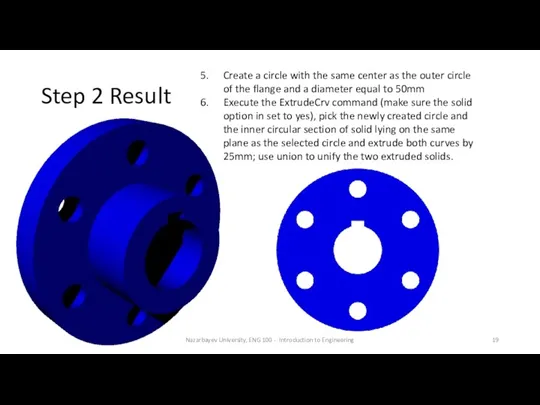
- 19. Step 2 Result Nazarbayev University, ENG 100 - Introduction to Engineering Create a circle with the
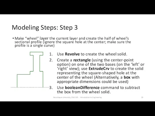
- 20. Modeling Steps: Step 3 Make “wheel” layer the current layer and create the half of wheel’s
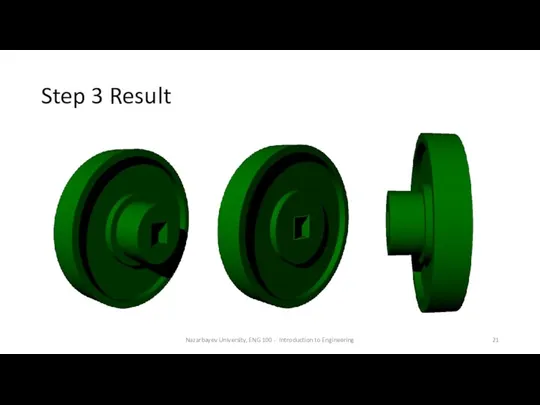
- 21. Step 3 Result Nazarbayev University, ENG 100 - Introduction to Engineering
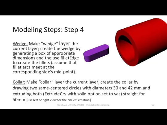
- 22. Modeling Steps: Step 4 Wedge: Make “wedge” layer the current layer; create the wedge by generating
- 23. Modeling Steps: Final step (Assembly) Nazarbayev University, ENG 100 - Introduction to Engineering
- 24. A simple circuit diagram Nazarbayev University, ENG 100 - Introduction to Engineering
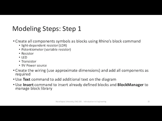
- 25. Modeling Steps: Step 1 Create all components symbols as blocks using Rhino’s block command light-dependent resistor
- 26. Step 1 Result Nazarbayev University, ENG 100 - Introduction to Engineering
- 27. Simplified Wind Turbine Blade Nazarbayev University, ENG 100 - Introduction to Engineering
- 28. Basic airfoil terminology Nazarbayev University, ENG 100 - Introduction to Engineering
- 29. Modeling Assumptions & input Airfoil type A shape: points in file airfoilA.txt Airfoil type B shape:
- 30. Modeling Steps: Step 1 Modify airfoilA.txt and airfoilB.txt to include the appropriate Rhino command (InterpCrv) to
- 31. Step 1 Result Nazarbayev University, ENG 100 - Introduction to Engineering
- 32. Modeling Steps: Step 2 Use ExtrudeCrv to model the part between L=5 and L=10 (solid option
- 33. Step 2 Result Nazarbayev University, ENG 100 - Introduction to Engineering Using the Zebra command you
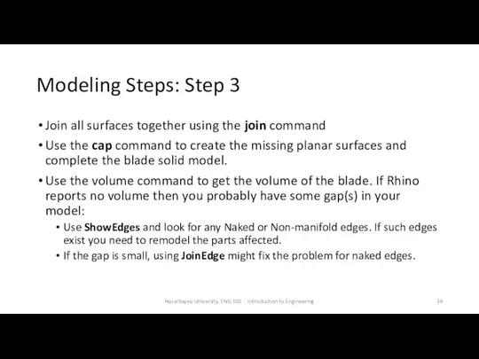
- 34. Modeling Steps: Step 3 Join all surfaces together using the join command Use the cap command
- 36. Скачать презентацию
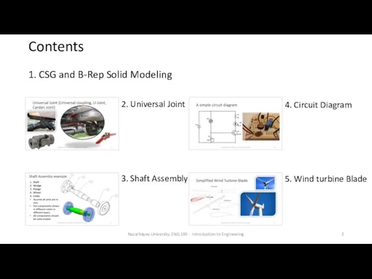
Contents
Nazarbayev University, ENG 100 - Introduction to Engineering
2. Universal Joint
3. Shaft
Contents
Nazarbayev University, ENG 100 - Introduction to Engineering
2. Universal Joint
3. Shaft
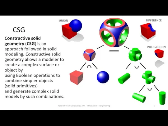
CSG
Constructive solid geometry (CSG) is an approach followed in solid modeling. Constructive solid
CSG
Constructive solid geometry (CSG) is an approach followed in solid modeling. Constructive solid
B-rep
The second and most popular approach in solid modeling and computer-aided design, is
B-rep
The second and most popular approach in solid modeling and computer-aided design, is
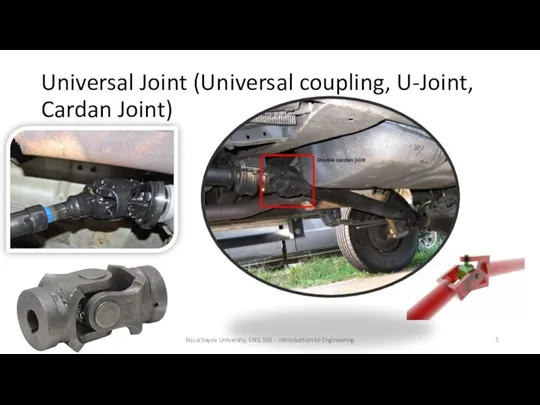
Universal Joint (Universal coupling, U-Joint, Cardan Joint)
Nazarbayev University, ENG 100 -
Universal Joint (Universal coupling, U-Joint, Cardan Joint)
Nazarbayev University, ENG 100 -
Nazarbayev University, ENG 100 - Introduction to Engineering
Nazarbayev University, ENG 100 - Introduction to Engineering
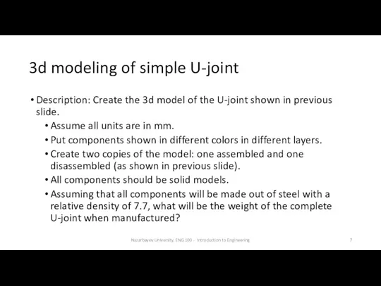
3d modeling of simple U-joint
Description: Create the 3d model of the
3d modeling of simple U-joint
Description: Create the 3d model of the
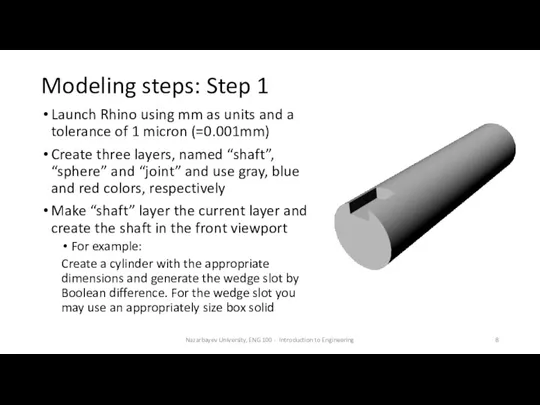
Modeling steps: Step 1
Launch Rhino using mm as units and a
Modeling steps: Step 1
Launch Rhino using mm as units and a
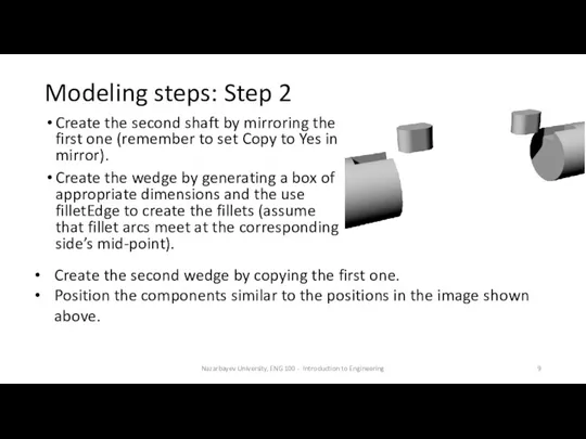
Modeling steps: Step 2
Create the second shaft by mirroring the first
Modeling steps: Step 2
Create the second shaft by mirroring the first
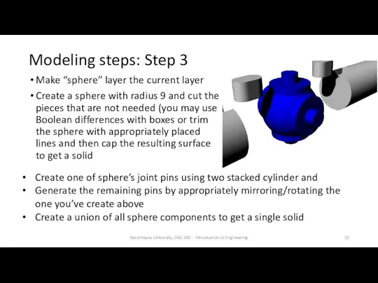
Modeling steps: Step 3
Make “sphere” layer the current layer
Create a sphere
Modeling steps: Step 3
Make “sphere” layer the current layer
Create a sphere
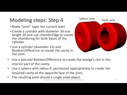
Modeling steps: Step 4
Make “joint” layer the current layer
Create a cylinder
Modeling steps: Step 4
Make “joint” layer the current layer
Create a cylinder
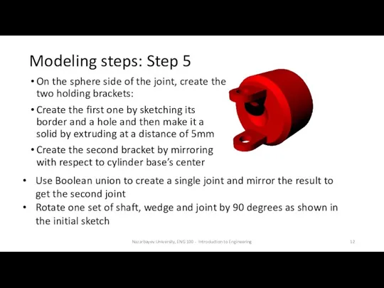
Modeling steps: Step 5
On the sphere side of the joint, create
Modeling steps: Step 5
On the sphere side of the joint, create
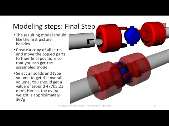
Modeling steps: Final Step
The resulting model should like the first picture
Modeling steps: Final Step
The resulting model should like the first picture
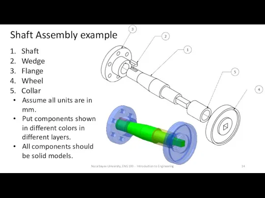
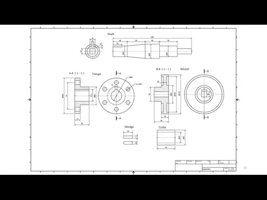
Shaft Assembly example
Nazarbayev University, ENG 100 - Introduction to Engineering
Shaft
Shaft Assembly example
Nazarbayev University, ENG 100 - Introduction to Engineering
Shaft
Nazarbayev University, ENG 100 - Introduction to Engineering
Nazarbayev University, ENG 100 - Introduction to Engineering
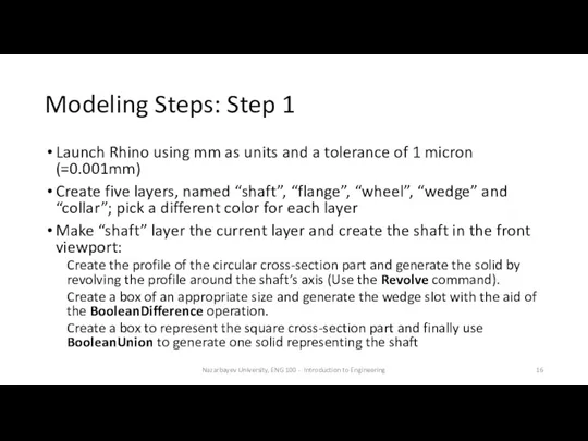
Modeling Steps: Step 1
Launch Rhino using mm as units and a
Modeling Steps: Step 1
Launch Rhino using mm as units and a
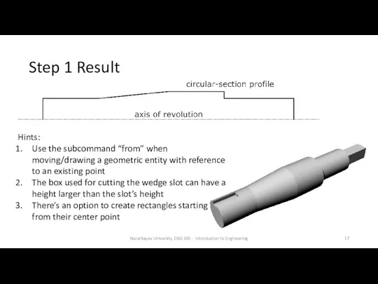
Step 1 Result
Nazarbayev University, ENG 100 - Introduction to Engineering
Hints:
Use the
Step 1 Result
Nazarbayev University, ENG 100 - Introduction to Engineering
Hints:
Use the
Modeling Steps: Step 2
Make “flange” layer the current layer and create
Modeling Steps: Step 2
Make “flange” layer the current layer and create
Step 2 Result
Nazarbayev University, ENG 100 - Introduction to Engineering
Create a
Step 2 Result
Nazarbayev University, ENG 100 - Introduction to Engineering
Create a
Modeling Steps: Step 3
Make “wheel” layer the current layer and create
Modeling Steps: Step 3
Make “wheel” layer the current layer and create
Step 3 Result
Nazarbayev University, ENG 100 - Introduction to Engineering
Step 3 Result
Nazarbayev University, ENG 100 - Introduction to Engineering
Modeling Steps: Step 4
Wedge: Make “wedge” layer the current layer; create
Modeling Steps: Step 4
Wedge: Make “wedge” layer the current layer; create
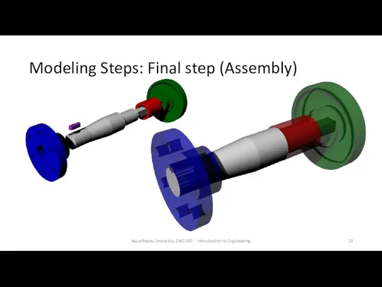
Modeling Steps: Final step (Assembly)
Nazarbayev University, ENG 100 - Introduction to
Modeling Steps: Final step (Assembly)
Nazarbayev University, ENG 100 - Introduction to
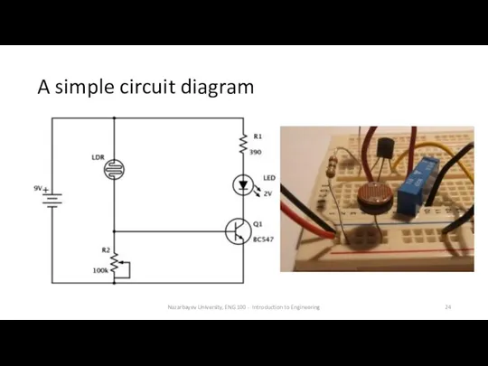
A simple circuit diagram
Nazarbayev University, ENG 100 - Introduction to Engineering
A simple circuit diagram
Nazarbayev University, ENG 100 - Introduction to Engineering
Modeling Steps: Step 1
Create all components symbols as blocks using Rhino’s
Modeling Steps: Step 1
Create all components symbols as blocks using Rhino’s
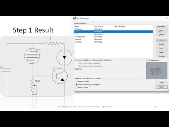
Step 1 Result
Nazarbayev University, ENG 100 - Introduction to Engineering
Step 1 Result
Nazarbayev University, ENG 100 - Introduction to Engineering
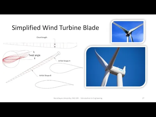
Simplified Wind Turbine Blade
Nazarbayev University, ENG 100 - Introduction to Engineering
Simplified Wind Turbine Blade
Nazarbayev University, ENG 100 - Introduction to Engineering
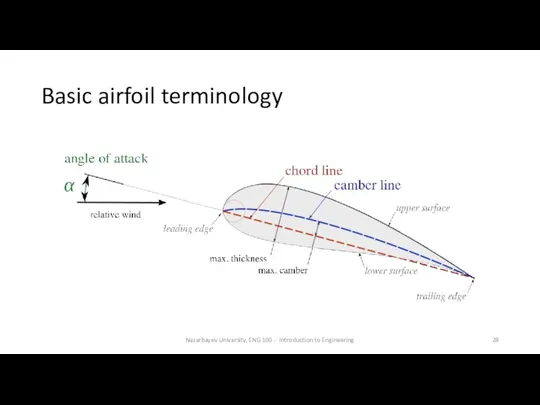
Basic airfoil terminology
Nazarbayev University, ENG 100 - Introduction to Engineering
Basic airfoil terminology
Nazarbayev University, ENG 100 - Introduction to Engineering
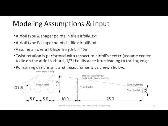
Modeling Assumptions & input
Airfoil type A shape: points in file airfoilA.txt
Airfoil
Modeling Assumptions & input
Airfoil type A shape: points in file airfoilA.txt
Airfoil
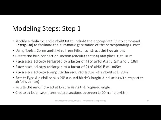
Modeling Steps: Step 1
Modify airfoilA.txt and airfoilB.txt to include the appropriate
Modeling Steps: Step 1
Modify airfoilA.txt and airfoilB.txt to include the appropriate
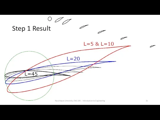
Step 1 Result
Nazarbayev University, ENG 100 - Introduction to Engineering
Step 1 Result
Nazarbayev University, ENG 100 - Introduction to Engineering
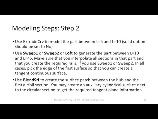
Modeling Steps: Step 2
Use ExtrudeCrv to model the part between L=5
Modeling Steps: Step 2
Use ExtrudeCrv to model the part between L=5
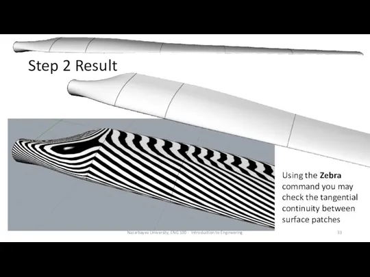
Step 2 Result
Nazarbayev University, ENG 100 - Introduction to Engineering
Using the
Step 2 Result
Nazarbayev University, ENG 100 - Introduction to Engineering
Using the
Modeling Steps: Step 3
Join all surfaces together using the join command
Use
Modeling Steps: Step 3
Join all surfaces together using the join command
Use
 Algebra relacyjna. Wprowadzenie do systemów baz danych
 Знакомство с ТРИК Студией
 Использование информационно-коммуникационных технологий в преподавании физики
 Метод побудови раціональної архітектури мережі 5G на основі існуючих 4G мереж
 Автоматизированные рабочие места автоматизированного управления (тема 9)
 Технологии 3Dпечати, применяемые на АО НПК Уралвагонзавод
 Анализ публикаций в этно-СМИ Московская немецкая газета. Итоговый исследовательский проект по дисциплине Этножурналистика
 Компьютерные презентации. Мультимедиа
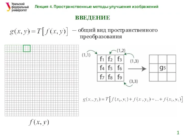 Пространственные методы улучшения изображений
 Интегрированный урок Математика - информатика
 How to install Java
 Нейронна мережа Джордана
 Разграничение прав доступа в сети. Общее дисковое пространство в локальной сети
 Массивы. Лекция 2
 Математичні функцій в С++
 Презентация Безопасный Интернет
 Информационная безопасность и кибербезопасность
 Лекция 2 – Основы языка C#
 Медиасистемы. Основы терминологического анализа. Основные типологические характеристики
 Управление памятью в ОСС
 Стандарты в области компьютерной графики
 1. Обработка символьной информации. Символьные переменные
 презентация Информационные технологии
 Представление (кодирование) чисел
 Графический дизайн
 Розробка системи обміну повідомленнями для Twitter, на базі мобільних технологій
 Кодирование графической информации
 BIM: Междисциплинарная координация