- GUI composer. Embedded development tools

Содержание
- 2. GUI Composer: See & Control Create GUI applications that provide: Visibility into what is happening in
- 3. When to use GUI Composer While debugging Create simple displays that allow you to quickly see
- 4. GUIs are Comprised of Widgets GUI Composer Applications are made up of HTML5 widgets Control widgets
- 5. Example Application: InstaSpin GUI application for demonstrating motor control development kit Widgets Knobs Graphs Meters Status
- 6. Customize how Widgets Look Most widgets can be customized to get the exact appearance that you
- 7. GUI Composer Builder Properties Projects Canvas Palette
- 8. Application Models Program Model CCS Debugger is used to translate symbols to addresses Writes to the
- 9. Program Model Symbol translation Symbols are translated to addresses by the CCS debugger Data display GUI
- 10. Streaming Model Data display Target application pushes data up to the GUI for display Data writes
- 11. Adjusting Data Format It is possible to adjust the value of data that is displayed Data
- 12. Types of Applications CCS Plug-in Feature within CCS Available from View menu within CCS Standalone application
- 13. Configuration View Appears when the standalone app starts up and shows the progress of the connection
- 14. GUI Composer Runtime GUI Composer applications need access to services (target read/write…) These services can be
- 15. Lab Requirements Software: Code Composer Studio v6.1.1.00022 GUI Composer (add-on in CCS) TivaWare for C series
- 16. Installation Instructions Download and install Code Composer Studio v6.1.1.00022 from http://processors.wiki.ti.com/index.php/Download_CCS Start CCS and click on
- 17. Tiva C LaunchPad: Hardware Setup Agenda … USB JTAG Connection
- 18. LAB 1: JTAG TRANSPORT LAB1A: CREATE AND USE DIAL WIDGET LAB1B: CREATE AND USE MORE WIDGETS
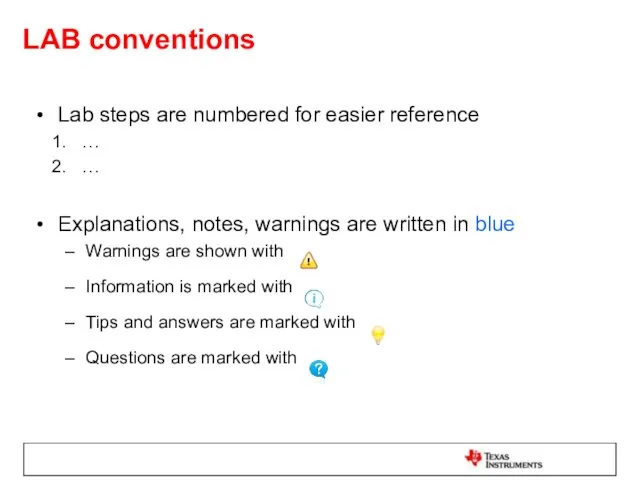
- 19. LAB conventions Lab steps are numbered for easier reference … … Explanations, notes, warnings are written
- 20. JTAG Transport: Exercise Summary Key Objectives Create a GUI that will create different widgets for controlling
- 21. LAB1A: CREATE AND USE DIAL WIDGET 15 MINUTES Open your lab materials and complete LAB 1A
- 22. Launch CCS Double click on the Code Composer Studio desktop icon Specify “GUI Composer Workshop” as
- 23. Import ‘blinky’ Project In the “Getting Started” page, click on Browse Examples Expand TivaWare_C_Series-2.1.0.12573->examples->boards->ek-tm4c123gxl->blinky, and select
- 24. Modify the Code Expand the project in the Project Explorer view to view its contents Double-click
- 25. Open GUI Composer Go to menu View -> GUI Composer Double-click on the GUI Composer tab
- 26. Create a New GUI Composer Project Click on the New Project button Name the project Lab1Blink
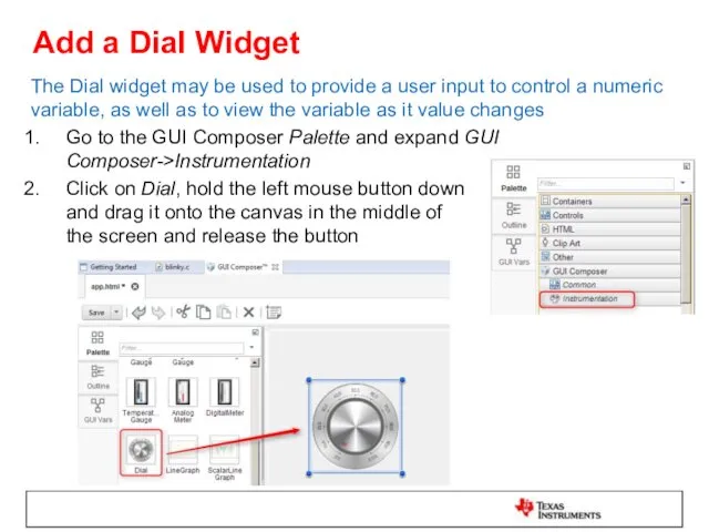
- 27. Add a Dial Widget The Dial widget may be used to provide a user input to
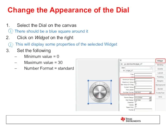
- 28. Change the Appearance of the Dial Select the Dial on the canvas There should be a
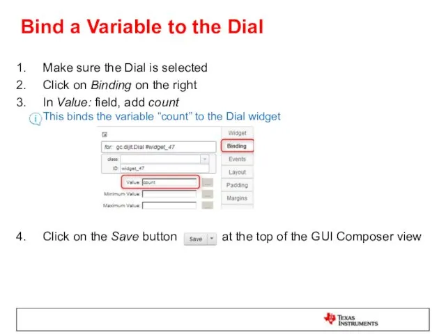
- 29. Bind a Variable to the Dial Make sure the Dial is selected Click on Binding on
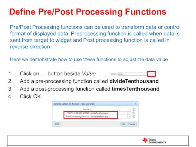
- 30. Define Pre/Post Processing Functions Pre/Post Processing functions can be used to transform data or control format
- 31. Define Pre/Post Processing Functions Double-click on app.js in the Projects area at the bottom left This
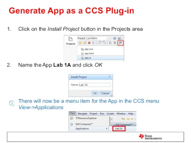
- 32. Generate App as a CCS Plug-in Click on the Install Project button in the Projects area
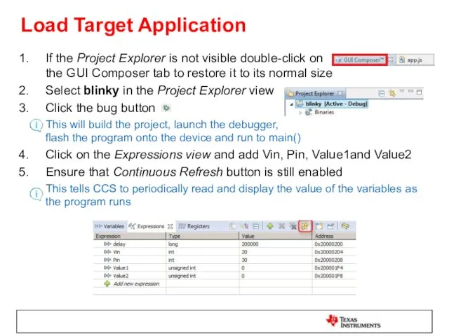
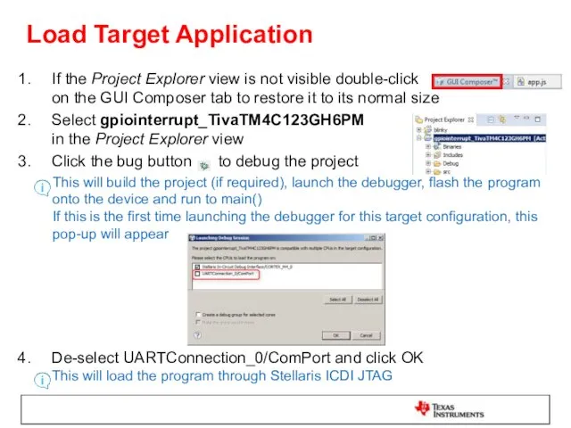
- 33. Load Target Application If the Project Explorer is not visible double-click on the GUI Composer tab
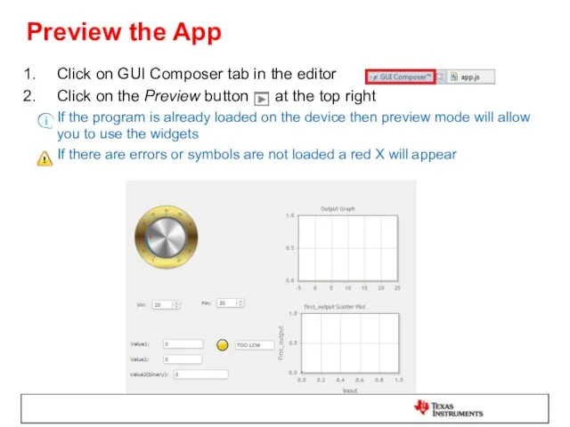
- 34. Preview the App Click on GUI Composer tab in the editor Click on the Preview button
- 35. Test the App using Preview Mode The App can be used either directly from Preview Mode
- 36. Test the App using Plug-in Go to menu View -> Applications -> Lab 1A to open
- 37. Clean Up Click the X on the Lab 1A tab to close the GUI composer app
- 38. LAB1B: CREATE AND USE MORE WIDGETS 30 MINUTES Open your lab materials and complete LAB 1B
- 39. Modify the Code This step modifies the program code to add a computation loop In Project
- 40. Add the following code at the top of the file after the declaration of variable delay
- 41. Add a Line Graph Widget The LineGraph widget is a graph that can show up to
- 42. Set the Properties of the Line Graph Select the LineGraph on the canvas There should be
- 43. Bind Variables to the Line Graph Make sure the Line Graph is selected Click on Binding
- 44. Add a Scatter Plot Widget The ScatterPlot widget is a graph that displays X-Y array data
- 45. Set the Properties of the Scatter Plot Select the Scatter Plot on the canvas There should
- 46. Bind Variables to the Scatter Plot Make sure the ScatterPlot is selected on the canvas Click
- 47. Add Label Widgets The Label widget is used to add text to the GUI application In
- 48. Add Number Spinner Widgets The NumberSpinner widget provides arrows to increment/decrement values and is useful to
- 49. Set Properties and Bindings for Number Spinners Select the NumberSpinner next to the Vin Label There
- 50. Set Properties and Bindings for Number Spinners Select the NumberSpinner next to the Pin Label There
- 51. Add more Label Widgets In the GUI Composer Palette, under GUI Composer->Common, click on Label, hold
- 52. Add TextBox Widgets The TextBox widget can be used to display a string or a number
- 53. Set Bindings for TextBoxes Select the first TextBox next to Label Value1 Click on Binding on
- 54. Set Bindings for TextBoxes Select the third TextBox next to Label Value2 (binary) Click on Binding
- 55. Set Bindings for TextBoxes In the converttoBinary function within app.js, change the code to: return parseInt(valueFromTarget,
- 56. Add MultiImage Widget The MultiImage widget can be used to display visual status information, such as
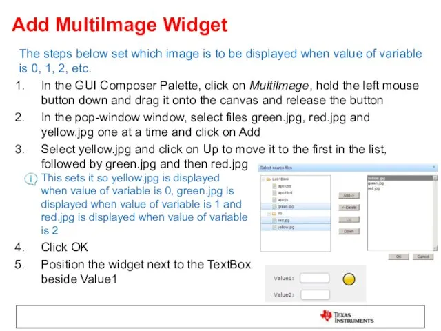
- 57. Add MultiImage Widget The steps below set which image is to be displayed when value of
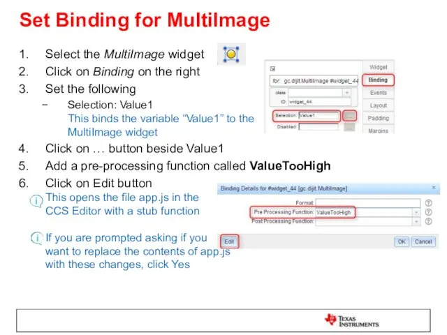
- 58. Set Binding for MultiImage Select the MultiImage widget Click on Binding on the right Set the
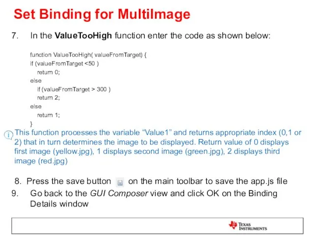
- 59. Set Binding for MultiImage In the ValueTooHigh function enter the code as shown below: function ValueTooHigh(
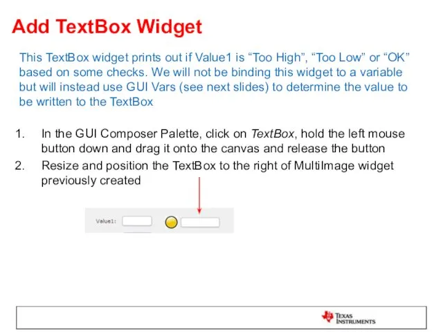
- 60. Add TextBox Widget This TextBox widget prints out if Value1 is “Too High”, “Too Low” or
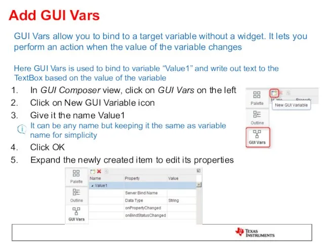
- 61. Add GUI Vars GUI Vars allow you to bind to a target variable without a widget.
- 62. Add GUI Vars For Server Bind Name, click on Value column and enter Value1 (this is
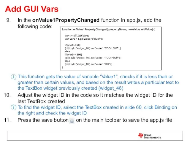
- 63. Add GUI Vars In the onValue1PropertyChanged function in app.js, add the following code: This function gets
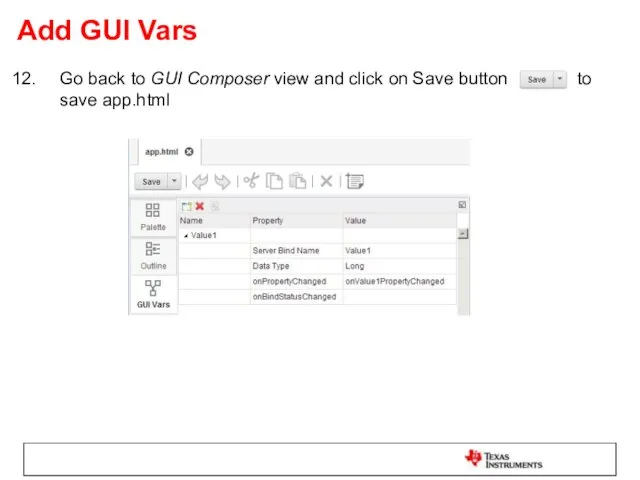
- 64. Add GUI Vars Go back to GUI Composer view and click on Save button to save
- 65. Load Target Application If the Project Explorer is not visible double-click on the GUI Composer tab
- 66. Preview the App Click on GUI Composer tab in the editor Click on the Preview button
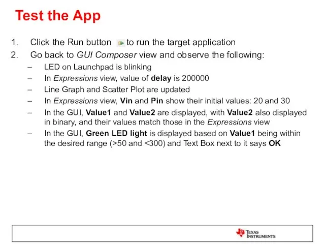
- 67. Test the App Click the Run button to run the target application Go back to GUI
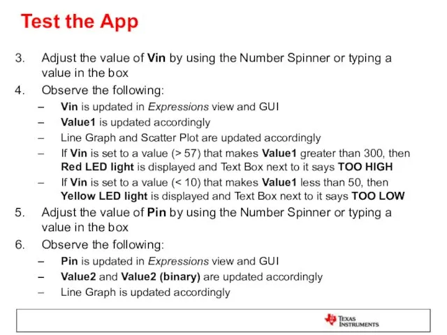
- 68. Test the App Adjust the value of Vin by using the Number Spinner or typing a
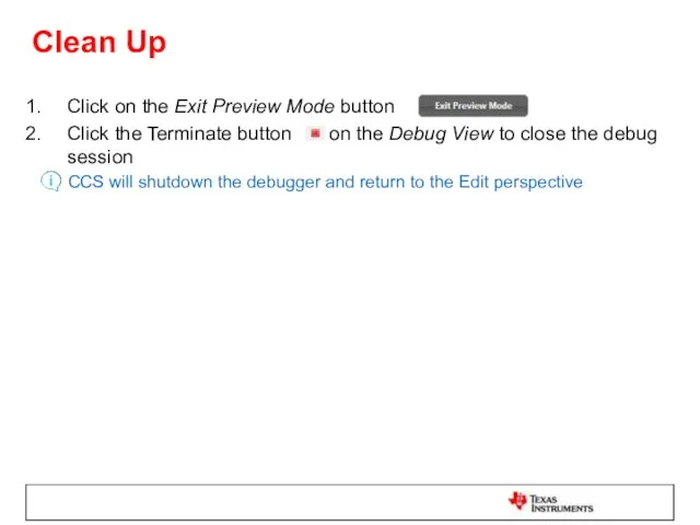
- 69. Clean Up Click on the Exit Preview Mode button Click the Terminate button on the Debug
- 70. Exporting the GUI Application Click on the GUI Composer view In the Projects area click on
- 71. Add App to GUI Composer Runtime Open a file explorer window Go to c:\ti Right click
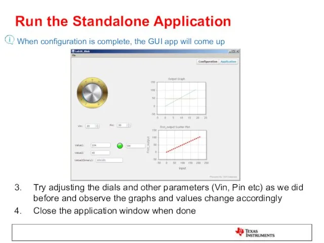
- 72. Run the Standalone Application Close CCS Double click on Launcher.exe located in c:\ti\guicomposer\webapps\Lab1B_Blink The splash screen
- 73. Run the Standalone Application When configuration is complete, the GUI app will come up Try adjusting
- 74. LAB 2: UART TRANSPORT
- 75. LAB conventions Lab steps are numbered for easier reference … … Explanations, notes, warnings are written
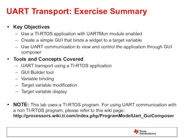
- 76. UART Transport: Exercise Summary Key Objectives Use a TI-RTOS application with UARTMon module enabled Create a
- 77. LAB 2: UART TRANSPORT EXAMPLE 20 MINUTES Open your lab materials and complete LAB 2
- 78. Launch CCS Double click on the Code Composer Studio desktop icon Specify “GUI Composer Workshop” as
- 79. Import and Build ‘GPIO Interrupt’ Project Go to menu View->Resource Explorer (Examples) Expand TI-RTOS for TivaC->Tiva
- 80. Import and Build ‘GPIO Interrupt’ Project In the right-pane, click on Step1 to Import the example
- 81. Review the RTOS configuration In Project Explorer view, expand the project gpiointerrupt_TivaTM4C123GH6PM Double-click on gpiointerrupt.cfg to
- 82. Add UART Communication to target config Find the COM Port number for your device using Device
- 83. Open GUI Composer Go to GUI Composer view if it is already open, else open the
- 84. Create a New GUI Composer Project If GUI Composer is being opened for the first time,
- 85. Add a Dial Widget The Dial widget may be used to provide a user input to
- 86. Change the Appearance of the Dial Select the Dial on the canvas There should be a
- 87. Bind a Variable to the Dial Make sure the Dial is selected Click on Binding on
- 88. Load Target Application If the Project Explorer view is not visible double-click on the GUI Composer
- 89. Load Symbols for UART Connection Once the program is running, load symbols for the UART connection
- 90. Preview the App Click on GUI Composer tab in the editor Click on the Preview button
- 91. Test the App Press the SW1 or SW2 buttons on the Launchpad With each button press,
- 92. Clean Up Click on the Exit Preview Mode button Click the Terminate button on the Debug
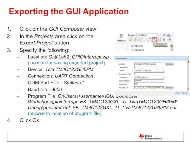
- 93. Exporting the GUI Application Click on the GUI Composer view In the Projects area click on
- 94. Add App to GUI Composer Runtime Open a file explorer window Go to c:\ti Right click
- 95. Run the Standalone Application Close CCS Power cycle the Launchpad Double click on Launcher.exe located in
- 96. Test the Standalone Application Press the SW1 or SW2 buttons on the Launchpad With each button
- 98. Скачать презентацию
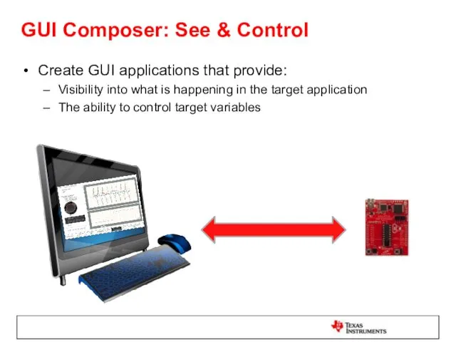
GUI Composer: See & Control
Create GUI applications that provide:
Visibility into what
GUI Composer: See & Control
Create GUI applications that provide:
Visibility into what
When to use GUI Composer
While debugging
Create simple displays that allow you
When to use GUI Composer
While debugging
Create simple displays that allow you
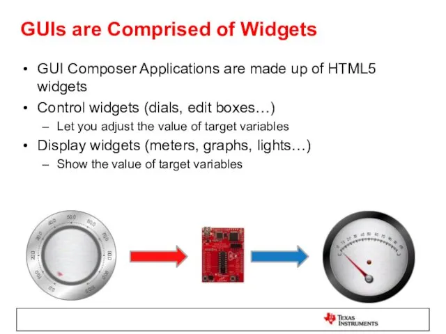
GUIs are Comprised of Widgets
GUI Composer Applications are made up of
GUIs are Comprised of Widgets
GUI Composer Applications are made up of
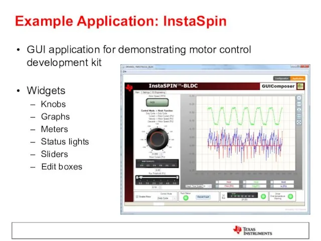
Example Application: InstaSpin
GUI application for demonstrating motor control development kit
Widgets
Knobs
Graphs
Meters
Status lights
Sliders
Edit
Example Application: InstaSpin
GUI application for demonstrating motor control development kit
Widgets
Knobs
Graphs
Meters
Status lights
Sliders
Edit
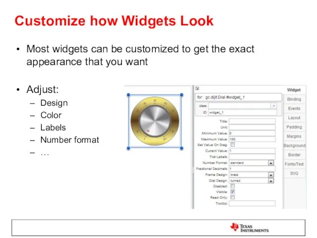
Customize how Widgets Look
Most widgets can be customized to get the
Customize how Widgets Look
Most widgets can be customized to get the
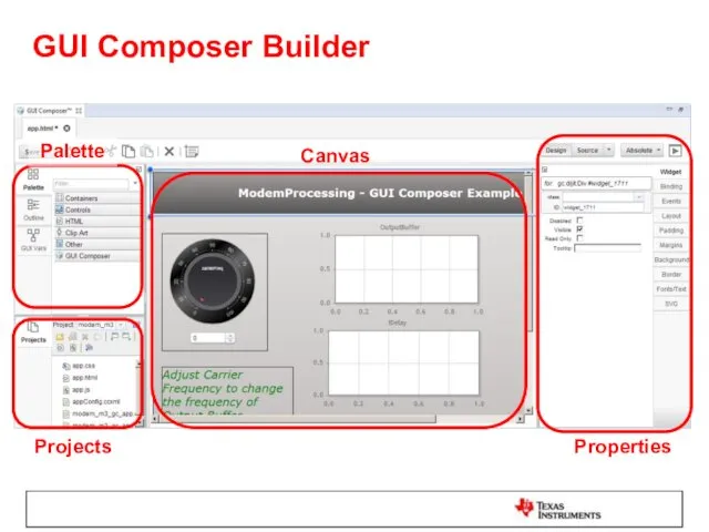
GUI Composer Builder
Properties
Projects
Canvas
Palette
GUI Composer Builder
Properties
Projects
Canvas
Palette
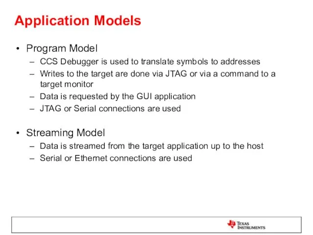
Application Models
Program Model
CCS Debugger is used to translate symbols to addresses
Writes
Application Models
Program Model
CCS Debugger is used to translate symbols to addresses
Writes
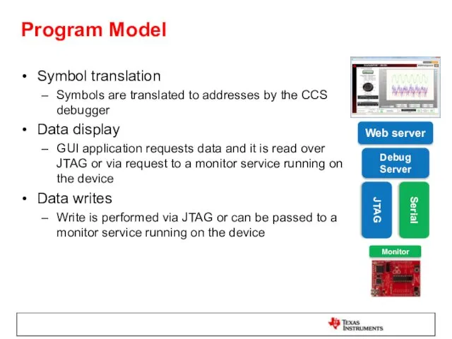
Program Model
Symbol translation
Symbols are translated to addresses by the CCS debugger
Data
Program Model
Symbol translation
Symbols are translated to addresses by the CCS debugger
Data
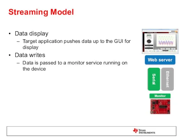
Streaming Model
Data display
Target application pushes data up to the GUI for
Streaming Model
Data display
Target application pushes data up to the GUI for
Adjusting Data Format
It is possible to adjust the value of data
Adjusting Data Format
It is possible to adjust the value of data
Types of Applications
CCS Plug-in
Feature within CCS
Available from View menu within CCS
Standalone
Types of Applications
CCS Plug-in
Feature within CCS
Available from View menu within CCS
Standalone
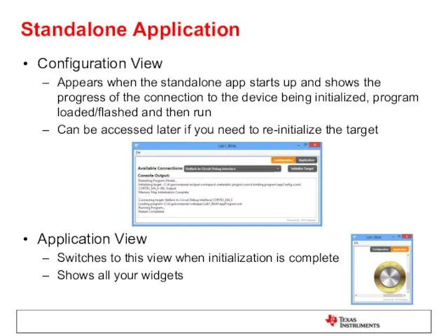
Configuration View
Appears when the standalone app starts up and shows the
Configuration View
Appears when the standalone app starts up and shows the
GUI Composer Runtime
GUI Composer applications need access to services (target read/write…)
These
GUI Composer Runtime
GUI Composer applications need access to services (target read/write…)
These
Lab Requirements
Software:
Code Composer Studio v6.1.1.00022
GUI Composer (add-on in CCS)
TivaWare for
Lab Requirements
Software:
Code Composer Studio v6.1.1.00022
GUI Composer (add-on in CCS)
TivaWare for
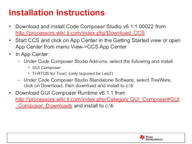
Installation Instructions
Download and install Code Composer Studio v6.1.1.00022 from
http://processors.wiki.ti.com/index.php/Download_CCS
Start
Installation Instructions
Download and install Code Composer Studio v6.1.1.00022 from
http://processors.wiki.ti.com/index.php/Download_CCS
Start
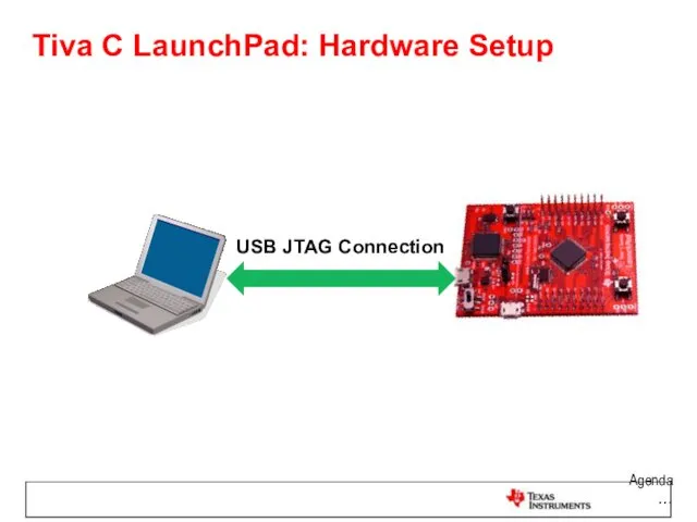
Tiva C LaunchPad: Hardware Setup
Agenda …
USB JTAG Connection
Tiva C LaunchPad: Hardware Setup
Agenda …
USB JTAG Connection
LAB 1: JTAG TRANSPORT
LAB1A: CREATE AND USE DIAL WIDGET
LAB1B: CREATE AND
LAB 1: JTAG TRANSPORT LAB1A: CREATE AND USE DIAL WIDGET LAB1B: CREATE AND

LAB conventions
Lab steps are numbered for easier reference
…
…
Explanations, notes, warnings are
LAB conventions
Lab steps are numbered for easier reference
…
…
Explanations, notes, warnings are
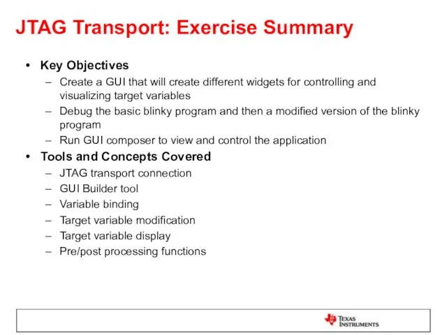
JTAG Transport: Exercise Summary
Key Objectives
Create a GUI that will create different
JTAG Transport: Exercise Summary
Key Objectives
Create a GUI that will create different
LAB1A: CREATE AND USE DIAL WIDGET
15 MINUTES
Open your lab materials and
LAB1A: CREATE AND USE DIAL WIDGET
15 MINUTES
Open your lab materials and

Launch CCS
Double click on the Code Composer Studio desktop icon
Specify “GUI
Launch CCS
Double click on the Code Composer Studio desktop icon
Specify “GUI
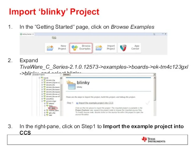
Import ‘blinky’ Project
In the “Getting Started” page, click on Browse Examples
Expand
Import ‘blinky’ Project
In the “Getting Started” page, click on Browse Examples
Expand
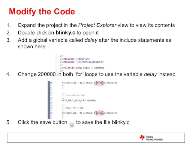
Modify the Code
Expand the project in the Project Explorer view to
Modify the Code
Expand the project in the Project Explorer view to
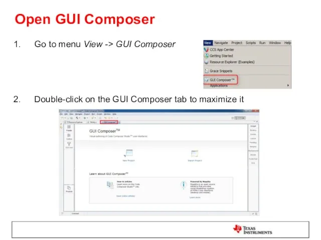
Open GUI Composer
Go to menu View -> GUI Composer
Double-click on the
Open GUI Composer
Go to menu View -> GUI Composer
Double-click on the
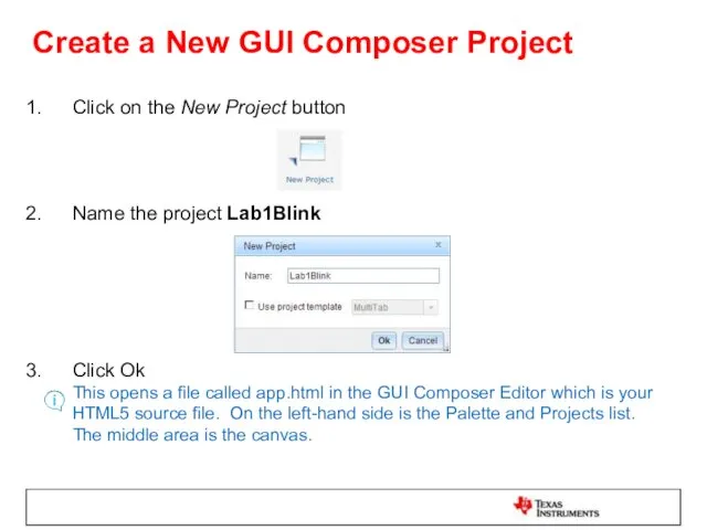
Create a New GUI Composer Project
Click on the New Project button
Name
Create a New GUI Composer Project
Click on the New Project button
Name
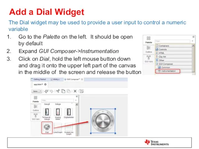
Add a Dial Widget
The Dial widget may be used to provide
Add a Dial Widget
The Dial widget may be used to provide
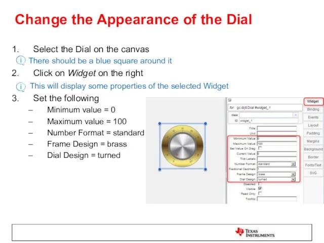
Change the Appearance of the Dial
Select the Dial on the canvas
Change the Appearance of the Dial
Select the Dial on the canvas
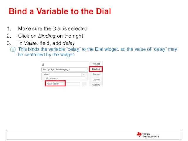
Bind a Variable to the Dial
Make sure the Dial is selected
Click
Bind a Variable to the Dial
Make sure the Dial is selected
Click
Define Pre/Post Processing Functions
Pre/Post Processing functions can be used to transform
Define Pre/Post Processing Functions
Pre/Post Processing functions can be used to transform

Define Pre/Post Processing Functions
Double-click on app.js in the Projects area at
Define Pre/Post Processing Functions
Double-click on app.js in the Projects area at
Generate App as a CCS Plug-in
Click on the Install Project button
Generate App as a CCS Plug-in
Click on the Install Project button
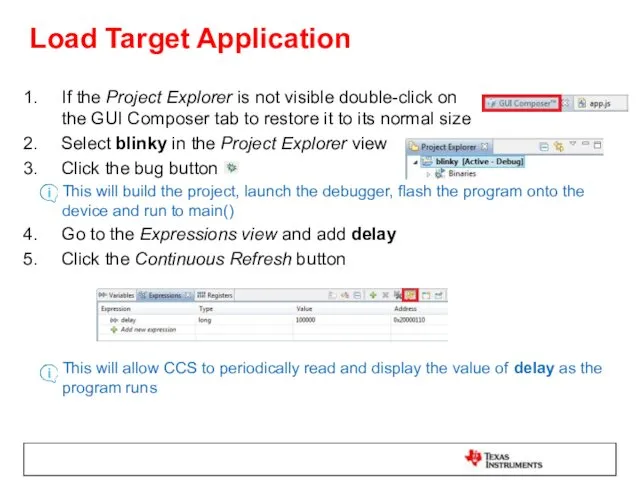
Load Target Application
If the Project Explorer is not visible double-click on
Load Target Application
If the Project Explorer is not visible double-click on
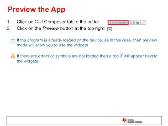
Preview the App
Click on GUI Composer tab in the editor
Click on
Preview the App
Click on GUI Composer tab in the editor
Click on
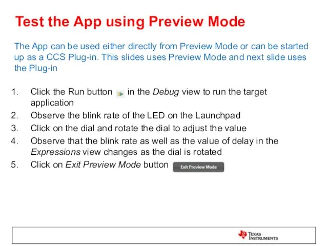
Test the App using Preview Mode
The App can be used either
Test the App using Preview Mode
The App can be used either
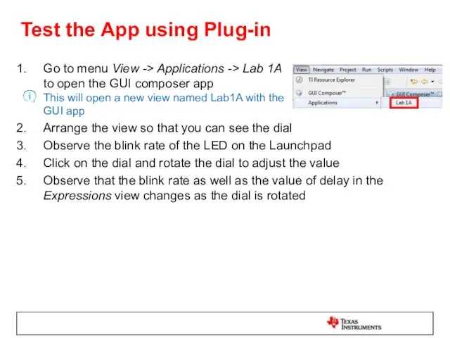
Test the App using Plug-in
Go to menu View -> Applications ->
Test the App using Plug-in
Go to menu View -> Applications ->
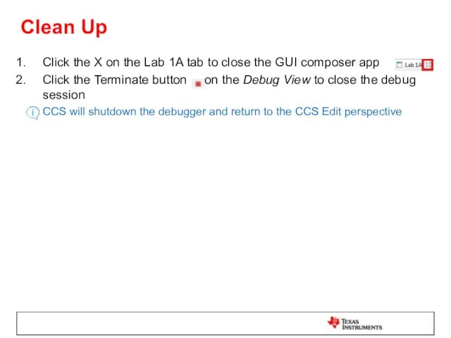
Clean Up
Click the X on the Lab 1A tab to close
Clean Up
Click the X on the Lab 1A tab to close
LAB1B: CREATE AND USE MORE WIDGETS
30 MINUTES
Open your lab materials and
LAB1B: CREATE AND USE MORE WIDGETS
30 MINUTES
Open your lab materials and
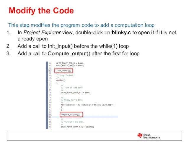
Modify the Code
This step modifies the program code to add a
Modify the Code
This step modifies the program code to add a
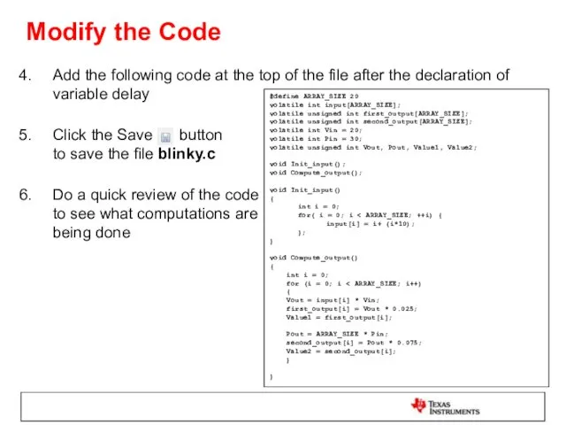
Add the following code at the top of the file after
Add the following code at the top of the file after
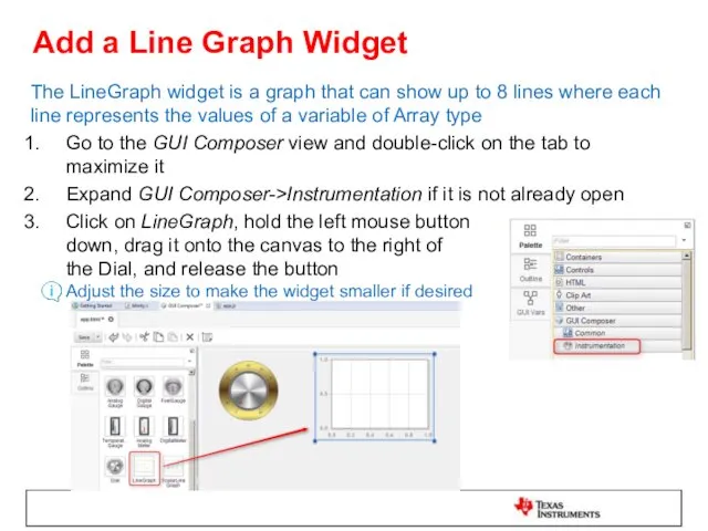
Add a Line Graph Widget
The LineGraph widget is a graph that
Add a Line Graph Widget
The LineGraph widget is a graph that
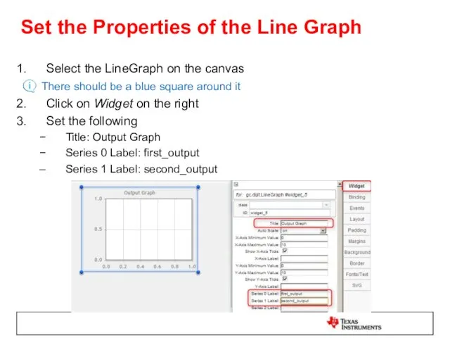
Set the Properties of the Line Graph
Select the LineGraph on the
Set the Properties of the Line Graph
Select the LineGraph on the
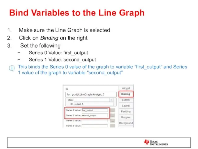
Bind Variables to the Line Graph
Make sure the Line Graph is
Bind Variables to the Line Graph
Make sure the Line Graph is
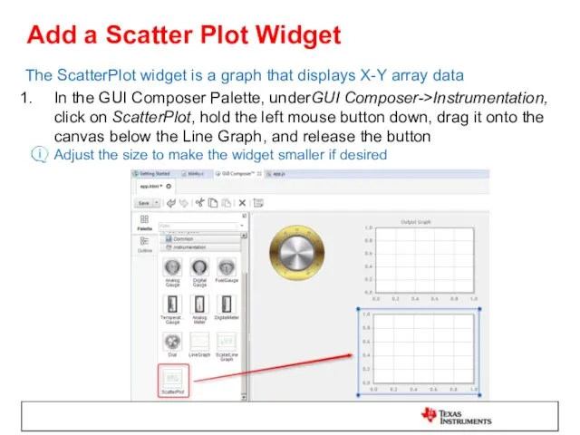
Add a Scatter Plot Widget
The ScatterPlot widget is a graph that
Add a Scatter Plot Widget
The ScatterPlot widget is a graph that
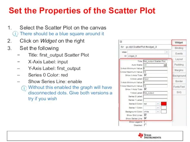
Set the Properties of the Scatter Plot
Select the Scatter Plot on
Set the Properties of the Scatter Plot
Select the Scatter Plot on
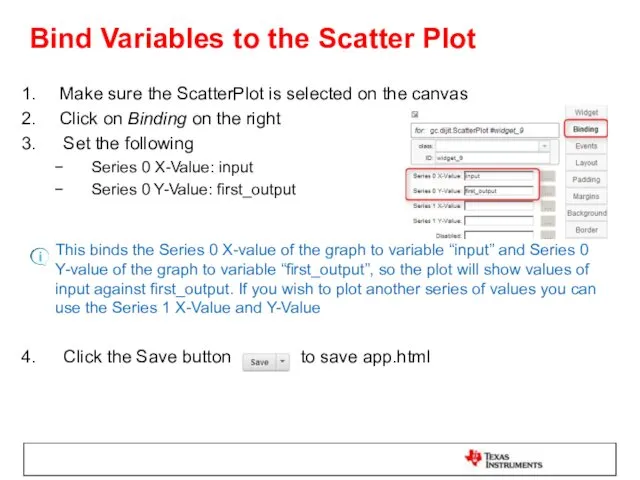
Bind Variables to the Scatter Plot
Make sure the ScatterPlot is selected
Bind Variables to the Scatter Plot
Make sure the ScatterPlot is selected
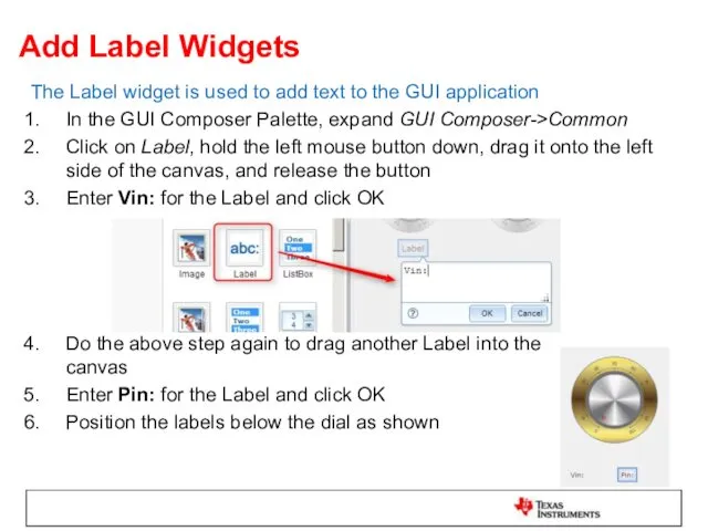
Add Label Widgets
The Label widget is used to add text to
Add Label Widgets
The Label widget is used to add text to
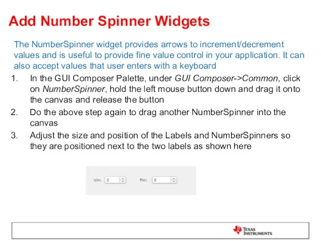
Add Number Spinner Widgets
The NumberSpinner widget provides arrows to increment/decrement values
Add Number Spinner Widgets
The NumberSpinner widget provides arrows to increment/decrement values
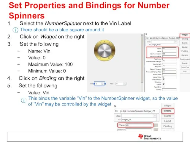
Set Properties and Bindings for Number Spinners
Select the NumberSpinner next to
Set Properties and Bindings for Number Spinners
Select the NumberSpinner next to
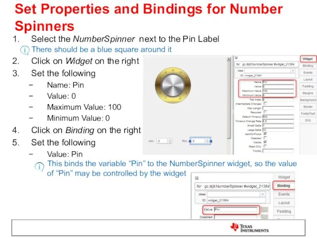
Set Properties and Bindings for Number Spinners
Select the NumberSpinner next to
Set Properties and Bindings for Number Spinners
Select the NumberSpinner next to
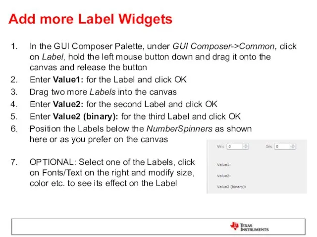
Add more Label Widgets
In the GUI Composer Palette, under GUI Composer->Common,
Add more Label Widgets
In the GUI Composer Palette, under GUI Composer->Common,
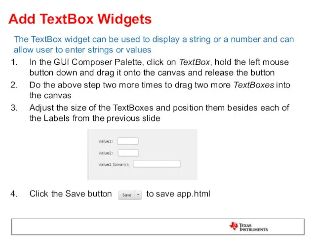
Add TextBox Widgets
The TextBox widget can be used to display a
Add TextBox Widgets
The TextBox widget can be used to display a
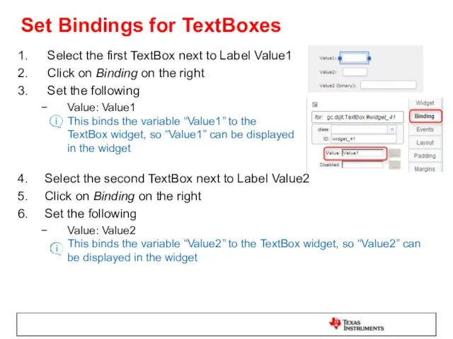
Set Bindings for TextBoxes
Select the first TextBox next to Label Value1
Click
Set Bindings for TextBoxes
Select the first TextBox next to Label Value1
Click
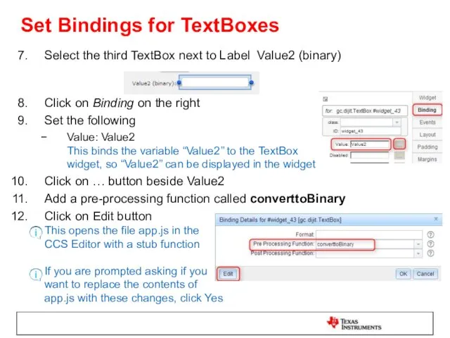
Set Bindings for TextBoxes
Select the third TextBox next to Label Value2
Set Bindings for TextBoxes
Select the third TextBox next to Label Value2
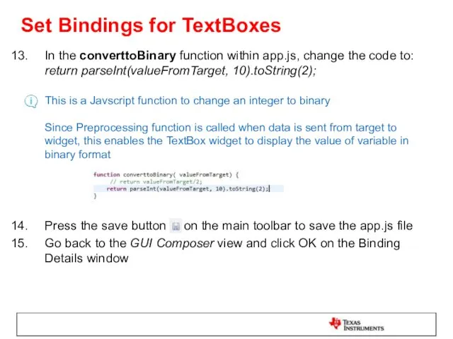
Set Bindings for TextBoxes
In the converttoBinary function within app.js, change the
Set Bindings for TextBoxes
In the converttoBinary function within app.js, change the
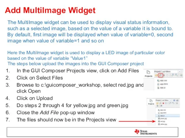
Add MultiImage Widget
The MultiImage widget can be used to display visual
Add MultiImage Widget
The MultiImage widget can be used to display visual
Add MultiImage Widget
The steps below set which image is to be
Add MultiImage Widget
The steps below set which image is to be
Set Binding for MultiImage
Select the MultiImage widget
Click on Binding on the
Set Binding for MultiImage
Select the MultiImage widget
Click on Binding on the
Set Binding for MultiImage
In the ValueTooHigh function enter the code as
Set Binding for MultiImage
In the ValueTooHigh function enter the code as
Add TextBox Widget
This TextBox widget prints out if Value1 is “Too
Add TextBox Widget
This TextBox widget prints out if Value1 is “Too
Add GUI Vars
GUI Vars allow you to bind to a target
Add GUI Vars
GUI Vars allow you to bind to a target
Add GUI Vars
For Server Bind Name, click on Value column and
Add GUI Vars
For Server Bind Name, click on Value column and
Add GUI Vars
In the onValue1PropertyChanged function in app.js, add the following
Add GUI Vars
In the onValue1PropertyChanged function in app.js, add the following
Add GUI Vars
Go back to GUI Composer view and click on
Add GUI Vars
Go back to GUI Composer view and click on
Load Target Application
If the Project Explorer is not visible double-click on
Load Target Application
If the Project Explorer is not visible double-click on
Preview the App
Click on GUI Composer tab in the editor
Click on
Preview the App
Click on GUI Composer tab in the editor
Click on
Test the App
Click the Run button to run the target application
Go
Test the App
Click the Run button to run the target application
Go
Test the App
Adjust the value of Vin by using the Number
Test the App
Adjust the value of Vin by using the Number
Clean Up
Click on the Exit Preview Mode button
Click the Terminate
Clean Up
Click on the Exit Preview Mode button
Click the Terminate
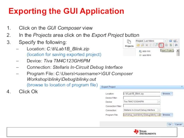
Exporting the GUI Application
Click on the GUI Composer view
In the Projects
Exporting the GUI Application
Click on the GUI Composer view
In the Projects
Add App to GUI Composer Runtime
Open a file explorer window
Go to
Add App to GUI Composer Runtime
Open a file explorer window
Go to
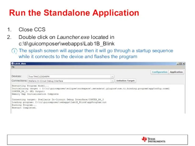
Run the Standalone Application
Close CCS
Double click on Launcher.exe located in c:\ti\guicomposer\webapps\Lab1B_Blink
The
Run the Standalone Application
Close CCS
Double click on Launcher.exe located in c:\ti\guicomposer\webapps\Lab1B_Blink
The
Run the Standalone Application
When configuration is complete, the GUI app will
Run the Standalone Application
When configuration is complete, the GUI app will
LAB 2: UART TRANSPORT
LAB 2: UART TRANSPORT
LAB conventions
Lab steps are numbered for easier reference
…
…
Explanations, notes, warnings are
LAB conventions
Lab steps are numbered for easier reference
…
…
Explanations, notes, warnings are
UART Transport: Exercise Summary
Key Objectives
Use a TI-RTOS application with UARTMon module
UART Transport: Exercise Summary
Key Objectives
Use a TI-RTOS application with UARTMon module
LAB 2: UART TRANSPORT EXAMPLE
20 MINUTES
Open your lab materials and complete
LAB 2: UART TRANSPORT EXAMPLE
20 MINUTES
Open your lab materials and complete
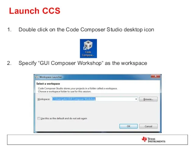
Launch CCS
Double click on the Code Composer Studio desktop icon
Specify “GUI
Launch CCS
Double click on the Code Composer Studio desktop icon
Specify “GUI
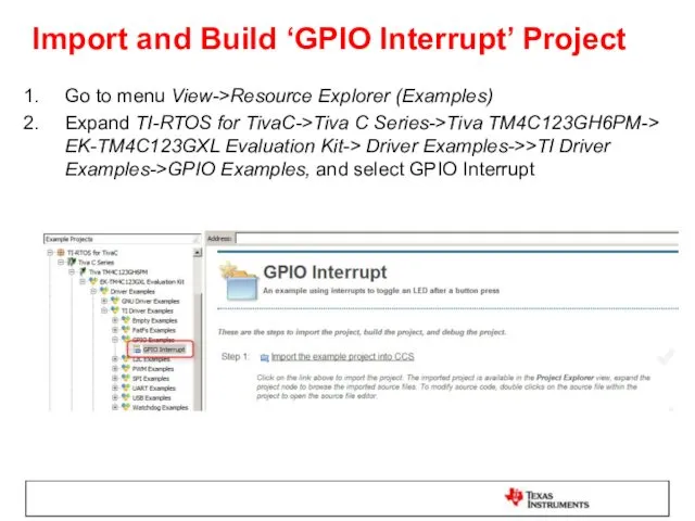
Import and Build ‘GPIO Interrupt’ Project
Go to menu View->Resource Explorer (Examples)
Expand
Import and Build ‘GPIO Interrupt’ Project
Go to menu View->Resource Explorer (Examples)
Expand
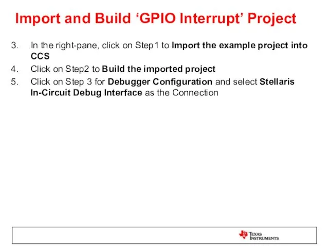
Import and Build ‘GPIO Interrupt’ Project
In the right-pane, click on Step1
Import and Build ‘GPIO Interrupt’ Project
In the right-pane, click on Step1
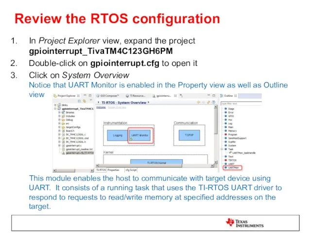
Review the RTOS configuration
In Project Explorer view, expand the project gpiointerrupt_TivaTM4C123GH6PM
Review the RTOS configuration
In Project Explorer view, expand the project gpiointerrupt_TivaTM4C123GH6PM
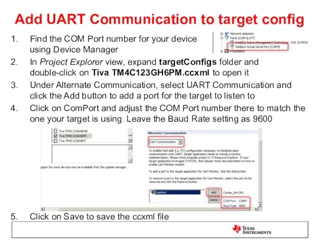
Add UART Communication to target config
Find the COM Port number for
Add UART Communication to target config
Find the COM Port number for
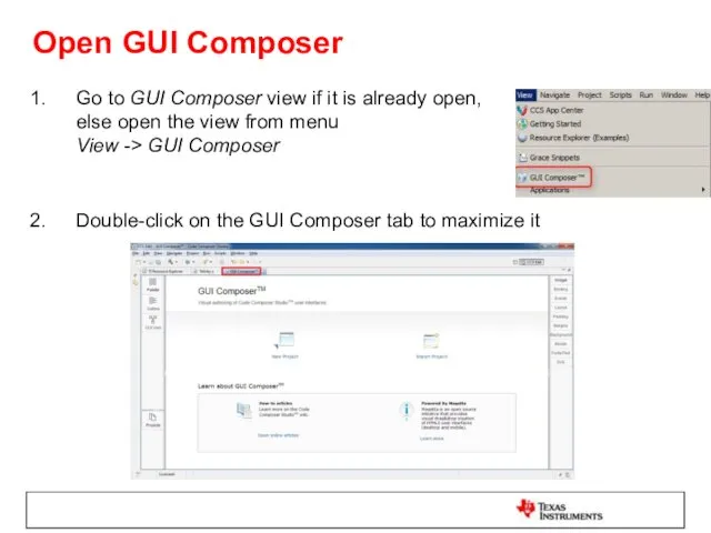
Open GUI Composer
Go to GUI Composer view if it is already
Open GUI Composer
Go to GUI Composer view if it is already
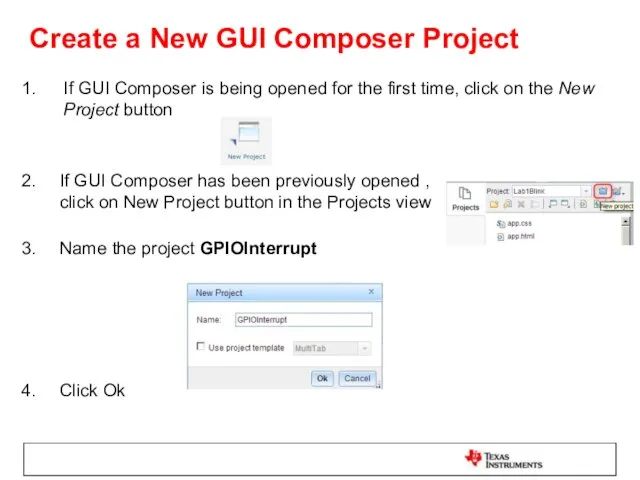
Create a New GUI Composer Project
If GUI Composer is being opened
Create a New GUI Composer Project
If GUI Composer is being opened
Add a Dial Widget
The Dial widget may be used to provide
Add a Dial Widget
The Dial widget may be used to provide
Change the Appearance of the Dial
Select the Dial on the canvas
Change the Appearance of the Dial
Select the Dial on the canvas
Bind a Variable to the Dial
Make sure the Dial is selected
Click
Bind a Variable to the Dial
Make sure the Dial is selected
Click
Load Target Application
If the Project Explorer view is not visible double-click
Load Target Application
If the Project Explorer view is not visible double-click
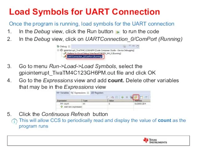
Load Symbols for UART Connection
Once the program is running, load symbols
Load Symbols for UART Connection
Once the program is running, load symbols
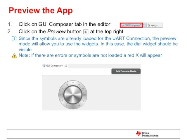
Preview the App
Click on GUI Composer tab in the editor
Click on
Preview the App
Click on GUI Composer tab in the editor
Click on
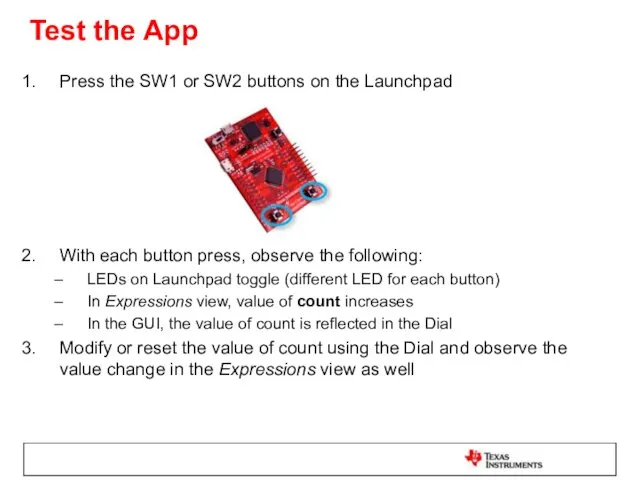
Test the App
Press the SW1 or SW2 buttons on the Launchpad
With
Test the App
Press the SW1 or SW2 buttons on the Launchpad
With
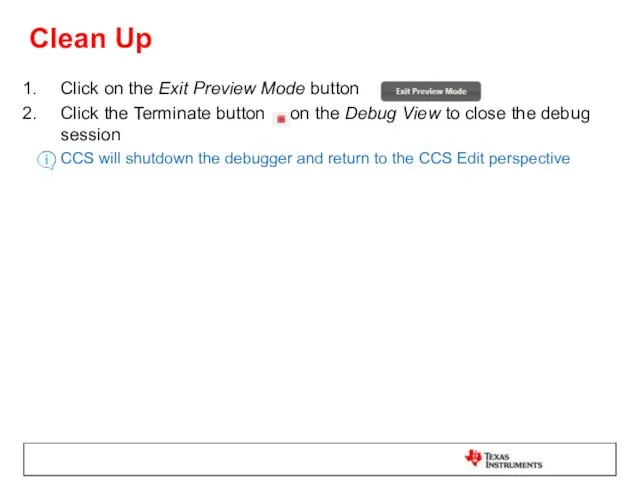
Clean Up
Click on the Exit Preview Mode button
Click the Terminate
Clean Up
Click on the Exit Preview Mode button
Click the Terminate
Exporting the GUI Application
Click on the GUI Composer view
In the Projects
Exporting the GUI Application
Click on the GUI Composer view
In the Projects
Add App to GUI Composer Runtime
Open a file explorer window
Go to
Add App to GUI Composer Runtime
Open a file explorer window
Go to
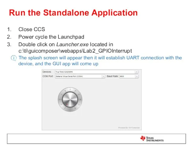
Run the Standalone Application
Close CCS
Power cycle the Launchpad
Double click on Launcher.exe
Run the Standalone Application
Close CCS
Power cycle the Launchpad
Double click on Launcher.exe
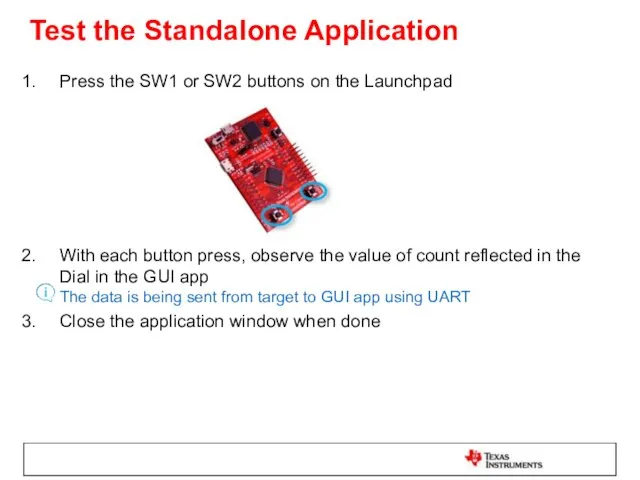
Test the Standalone Application
Press the SW1 or SW2 buttons on the
Test the Standalone Application
Press the SW1 or SW2 buttons on the
 Применение UML при разработке программного обеспечения
 Лекция №5. Количество информации и избыточность
 Введение в WEB-разработку
 History of creation Facebook
 Программирование на языке Python
 Новости недели в РФ
 Искусственный интеллект. Межуниверситетский проект
 Программирование на языке Java
 Организация защиты информационной системы предприятия от несанкционированного доступа на основе применения СКУД
 Лекция 1. Основы компьютерных сетей. История развития
 Единый государственный экзамен. Часть В
 Презентация-игра Продолжи ряд Диск
 Равносильные логические выражения
 Информация Свойства информации
 Системология. Системы и их элементы
 Встроенные функции. Функциональное программирование в Python. Лекция 5
 The project mass media
 Атрибуты deftemplate
 Логическое проектирование базы данных
 Основы логики
 Python.Основы Циклы While. For. Лекция 3.2
 Техніка безпеки. Електронна пошта. Урок 1
 Сообщество adidas runners и RunClubKirov в Strava
 9 класс Презентации к урокам
 Цифровое депо
 Введение в Matlab
 Язык программирования PROLOG
 Методы шифрования