- Memory management. Implementation issues & segmentation

Содержание
- 2. Team Instructor Giancarlo Succi Teaching Assistants (Vladimir Ivanov) Luiz Araujo (also Tutorial Instructor) Nikita Lozhnikov Nikita
- 3. Sources These slides have been adapted from the original slides of the adopted book: Tanenbaum &
- 4. Implementation Issues Involvement with Paging Page Fault Handling Instruction Backup Locking Pages in Memory Backing Store
- 5. OS Involvement with Paging (1) Four situations for paging-related work: Process creation Process execution Page fault
- 6. OS Involvement with Paging (2) Process creation: Determine how large the program and data will be
- 7. OS Involvement with Paging (3) Process execution: Reset the MMU for the new process and flush
- 8. OS Involvement with Paging (4) Page fault: Read out hardware registers to determine which virtual address
- 9. OS Involvement with Paging (5) Process termination: Release the page table, its pages, and the disk
- 10. Page Fault Handling (1) Sequence of events on a page fault: The hardware traps to kernel,
- 11. Page Fault Handling (2) If frame selected (to be replaced) is dirty, page is scheduled for
- 12. Page Fault Handling (3) Faulting instruction is backed up to state it had when it began
- 13. Instruction Backup (1) When a program references a page that is not in memory, the instruction
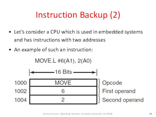
- 14. Instruction Backup (2) Let’s consider a CPU which is used in embedded systems and has instructions
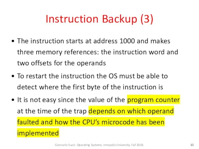
- 15. Instruction Backup (3) The instruction starts at address 1000 and makes three memory references: the instruction
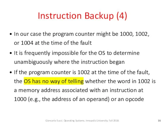
- 16. Instruction Backup (4) In our case the program counter might be 1000, 1002, or 1004 at
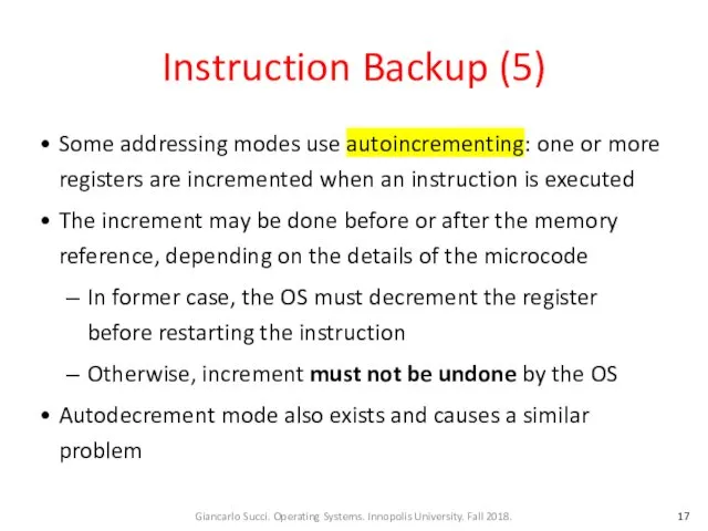
- 17. Instruction Backup (5) Some addressing modes use autoincrementing: one or more registers are incremented when an
- 18. Instruction Backup (6) A possible solution is to have a hidden internal register into which the
- 19. Locking Pages in Memory (1) Consider a process that has just issued a system call to
- 20. Locking Pages in Memory (2) If the paging algorithm is global, there is a small, but
- 21. Locking Pages in Memory (3) One solution to this problem is to lock pages engaged in
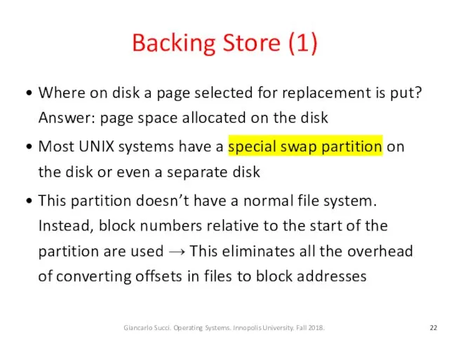
- 22. Backing Store (1) Where on disk a page selected for replacement is put? Answer: page space
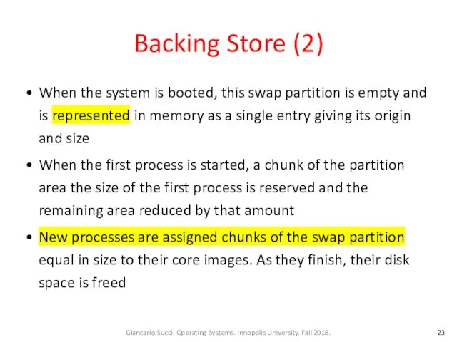
- 23. Backing Store (2) When the system is booted, this swap partition is empty and is represented
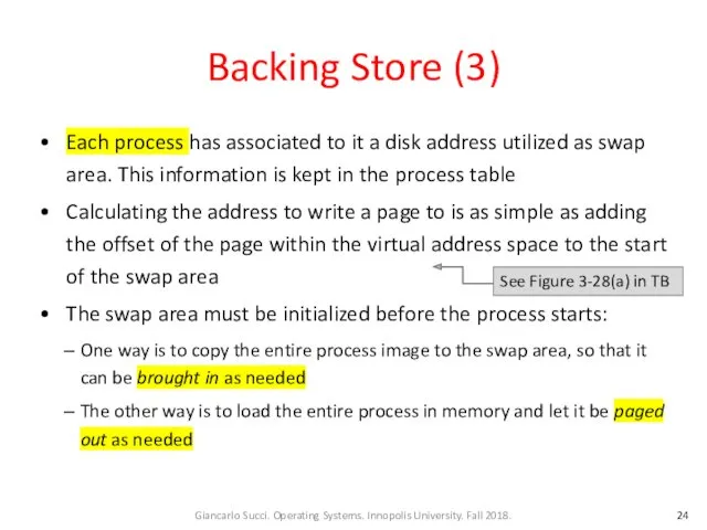
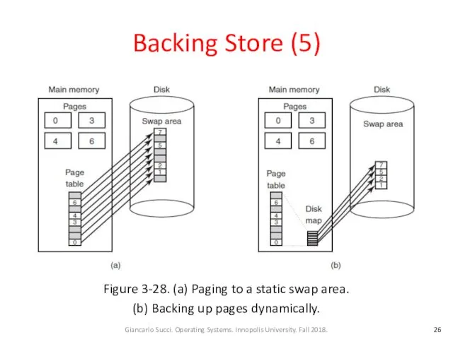
- 24. Backing Store (3) Each process has associated to it a disk address utilized as swap area.
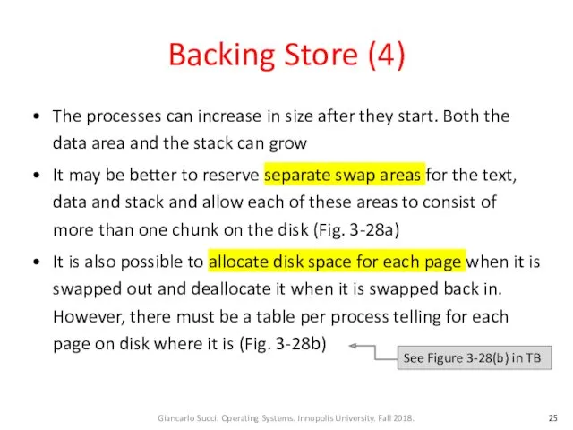
- 25. Backing Store (4) The processes can increase in size after they start. Both the data area
- 26. Backing Store (5) Figure 3-28. (a) Paging to a static swap area. (b) Backing up pages
- 27. Backing Store (6) Having a fixed swap partition is not always possible. In this case, one
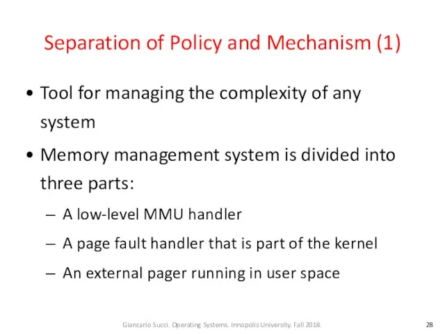
- 28. Separation of Policy and Mechanism (1) Tool for managing the complexity of any system Memory management
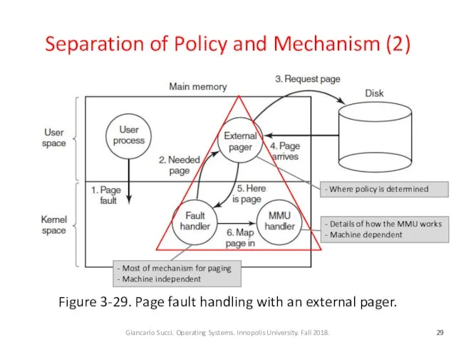
- 29. Separation of Policy and Mechanism (2) Figure 3-29. Page fault handling with an external pager. -
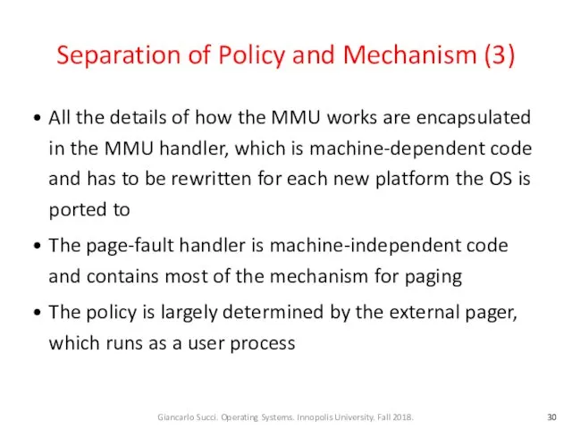
- 30. Separation of Policy and Mechanism (3) All the details of how the MMU works are encapsulated
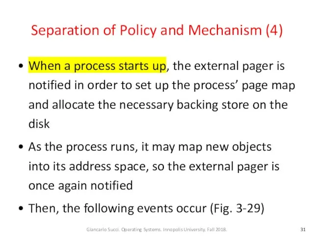
- 31. Separation of Policy and Mechanism (4) When a process starts up, the external pager is notified
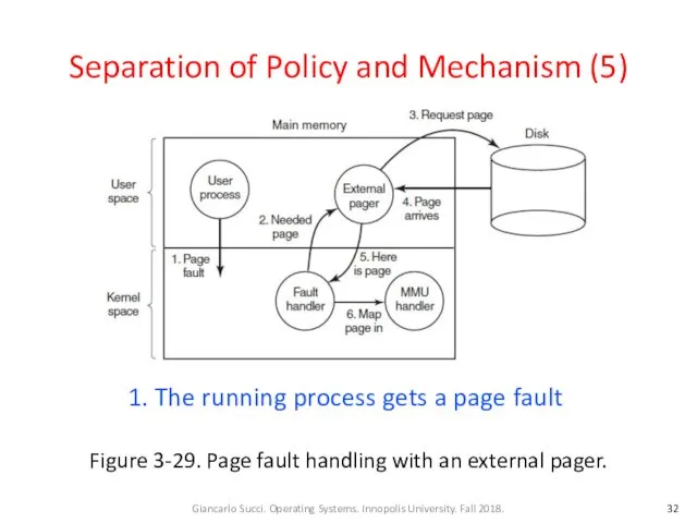
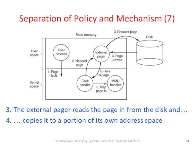
- 32. Separation of Policy and Mechanism (5) Figure 3-29. Page fault handling with an external pager. 1.
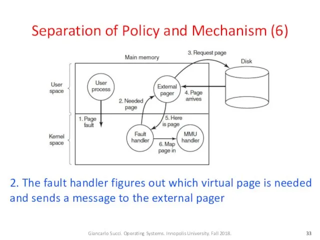
- 33. Separation of Policy and Mechanism (6) 2. The fault handler figures out which virtual page is
- 34. Separation of Policy and Mechanism (7) 3. The external pager reads the page in from the
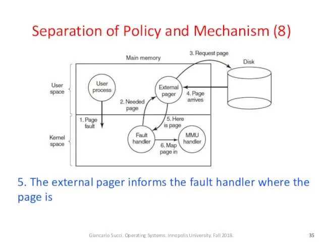
- 35. Separation of Policy and Mechanism (8) 5. The external pager informs the fault handler where the
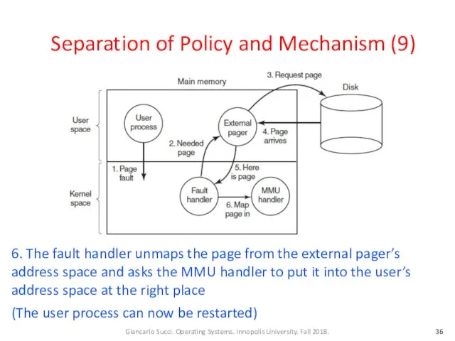
- 36. Separation of Policy and Mechanism (9) 6. The fault handler unmaps the page from the external
- 37. Separation of Policy and Mechanism (10) The page replacement algorithm can be put in the external
- 38. Separation of Policy and Mechanism (11) The main advantage of this implementation is more modular code
- 39. Segmentation (1) Examples of several tables generated by compiler: The source text being saved for the
- 40. Segmentation (2) Figure 3-30. In a one-dimensional address space with growing tables, one table may bump
- 41. Segmentation (3) What is needed is a way of freeing the programmer from having to manage
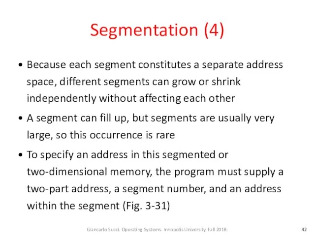
- 42. Segmentation (4) Because each segment constitutes a separate address space, different segments can grow or shrink
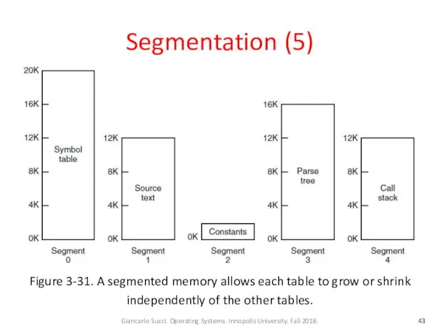
- 43. Segmentation (5) Figure 3-31. A segmented memory allows each table to grow or shrink independently of
- 44. Segmentation (6) A segment is a logical entity that might contain a procedure, or an array,
- 45. Segmentation (7) Advantages of segments (cont.): If the procedure in segment n is subsequently modified and
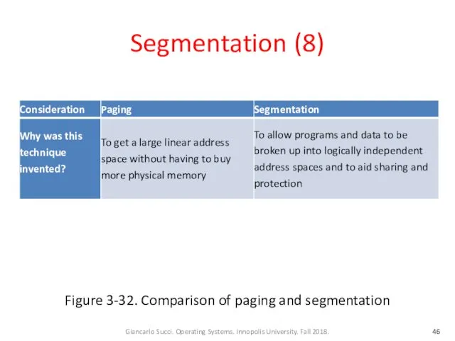
- 46. Segmentation (8) Figure 3-32. Comparison of paging and segmentation
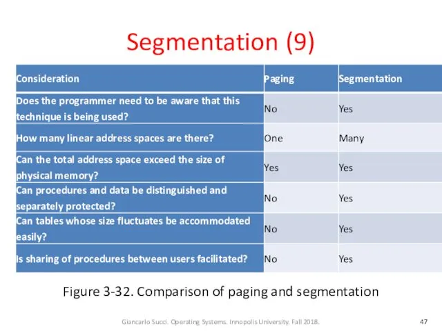
- 47. Segmentation (9) Figure 3-32. Comparison of paging and segmentation
- 48. Implementation of Pure Segmentation (1) Consider a piece of memory containing five segments (Fig. 3-33a) If
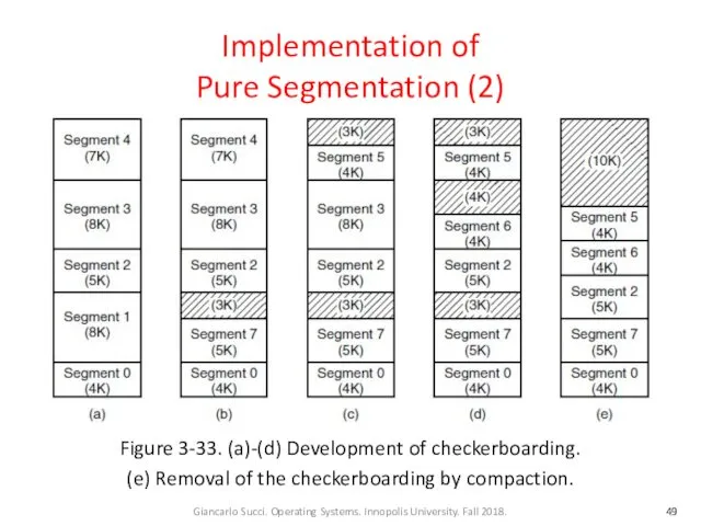
- 49. Implementation of Pure Segmentation (2) Figure 3-33. (a)-(d) Development of checkerboarding. (e) Removal of the checkerboarding
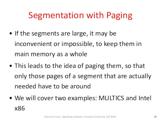
- 50. Segmentation with Paging If the segments are large, it may be inconvenient or impossible, to keep
- 51. Segmentation with Paging: MULTICS (1) MULTICS ran on the Honeywell 6000 machines and their descendants and
- 52. Segmentation with Paging: MULTICS (2) Each MULTICS program had a segment table, with one descriptor per
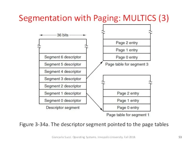
- 53. Segmentation with Paging: MULTICS (3) Figure 3-34a. The descriptor segment pointed to the page tables
- 54. Segmentation with Paging: MULTICS (4) Physical addresses were 24 bits and pages were aligned on 64-byte
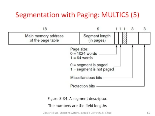
- 55. Segmentation with Paging: MULTICS (5) Figure 3-34. A segment descriptor. The numbers are the field lengths
- 56. Segmentation with Paging: MULTICS (6) Each segment was an ordinary virtual address space and was paged
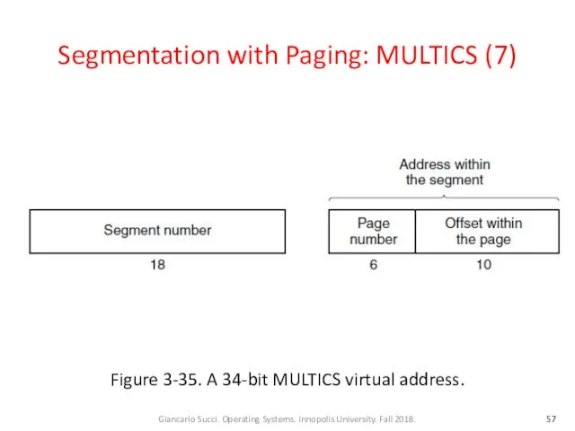
- 57. Segmentation with Paging: MULTICS (7) Figure 3-35. A 34-bit MULTICS virtual address.
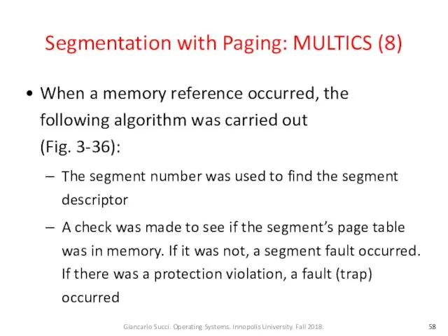
- 58. Segmentation with Paging: MULTICS (8) When a memory reference occurred, the following algorithm was carried out
- 59. Segmentation with Paging: MULTICS (9) Memory reference with segments (cont.): The page table entry for the
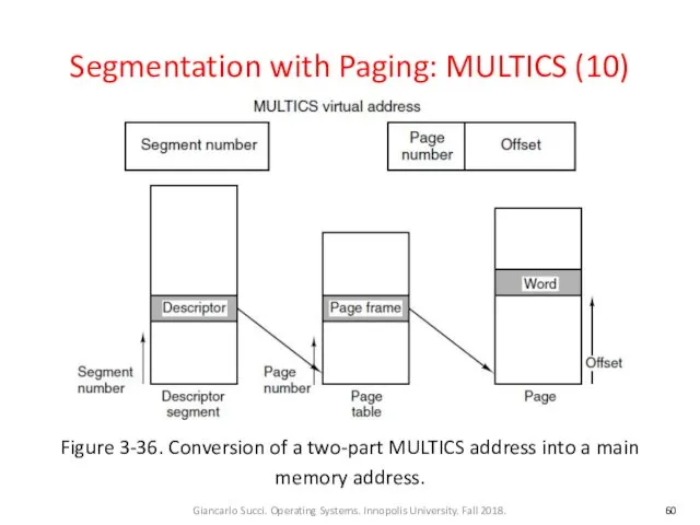
- 60. Segmentation with Paging: MULTICS (10) Figure 3-36. Conversion of a two-part MULTICS address into a main
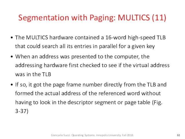
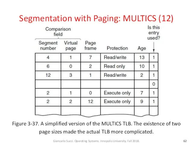
- 61. Segmentation with Paging: MULTICS (11) The MULTICS hardware contained a 16-word high-speed TLB that could search
- 62. Segmentation with Paging: MULTICS (12) Figure 3-37. A simplified version of the MULTICS TLB. The existence
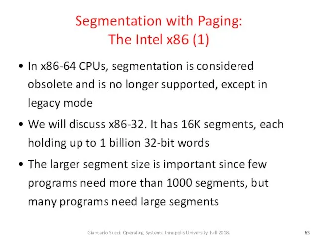
- 63. Segmentation with Paging: The Intel x86 (1) In x86-64 CPUs, segmentation is considered obsolete and is
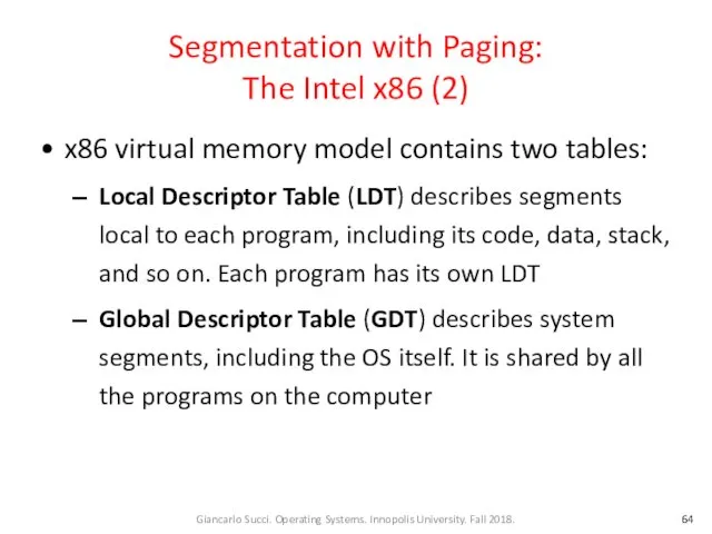
- 64. Segmentation with Paging: The Intel x86 (2) x86 virtual memory model contains two tables: Local Descriptor
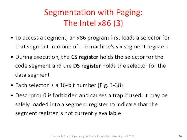
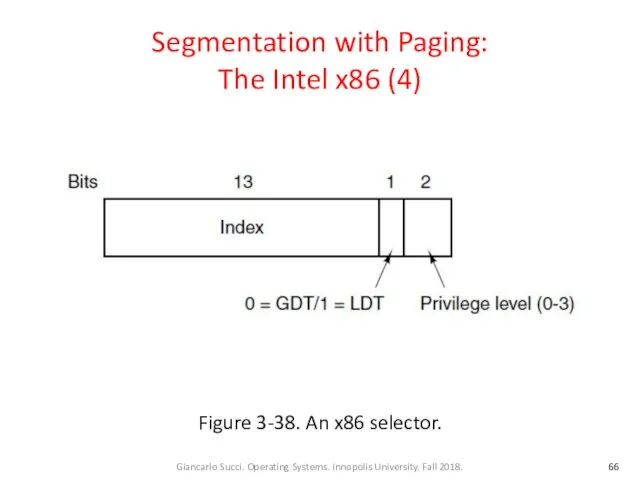
- 65. Segmentation with Paging: The Intel x86 (3) To access a segment, an x86 program first loads
- 66. Segmentation with Paging: The Intel x86 (4) Figure 3-38. An x86 selector.
- 67. Segmentation with Paging: The Intel x86 (5) At the time a selector is loaded into a
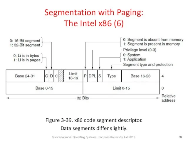
- 68. Segmentation with Paging: The Intel x86 (6) Figure 3-39. x86 code segment descriptor. Data segments differ
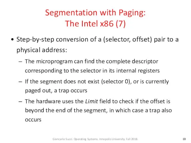
- 69. Segmentation with Paging: The Intel x86 (7) Step-by-step conversion of a (selector, offset) pair to a
- 70. Segmentation with Paging: The Intel x86 (7) Conversion (cont.): If the Gbit (Granularity) field is 0,
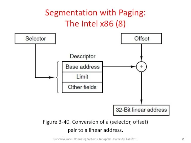
- 71. Segmentation with Paging: The Intel x86 (8) Figure 3-40. Conversion of a (selector, offset) pair to
- 72. Segmentation with Paging: The Intel x86 (9) Conversion (cont.): If paging is enabled, the linear address
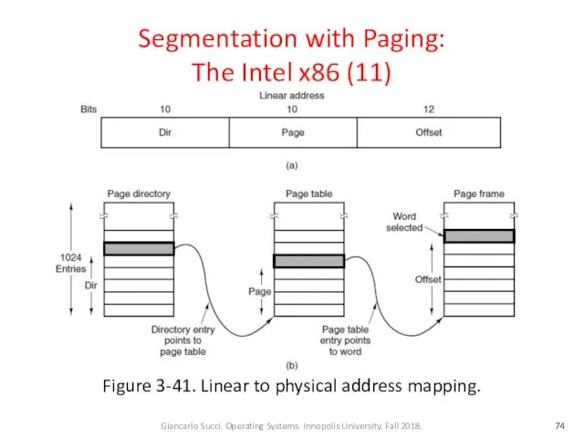
- 73. Segmentation with Paging: The Intel x86 (10) Conversion (cont.): The Dir field of a linear address
- 74. Segmentation with Paging: The Intel x86 (11) Figure 3-41. Linear to physical address mapping.
- 75. Week 09 – Lecture 1 End
- 77. Скачать презентацию
Team
Instructor
Giancarlo Succi
Teaching Assistants
(Vladimir Ivanov)
Luiz Araujo (also Tutorial Instructor)
Nikita Lozhnikov
Nikita Bogomazov
Team
Instructor
Giancarlo Succi
Teaching Assistants
(Vladimir Ivanov)
Luiz Araujo (also Tutorial Instructor)
Nikita Lozhnikov
Nikita Bogomazov
Sources
These slides have been adapted from the original slides of the
Sources
These slides have been adapted from the original slides of the
Implementation Issues
Involvement with Paging
Page Fault Handling
Instruction Backup
Locking Pages in Memory
Backing Store
Separation
Implementation Issues
Involvement with Paging
Page Fault Handling
Instruction Backup
Locking Pages in Memory
Backing Store
Separation
OS Involvement with Paging (1)
Four situations for paging-related work:
Process creation
Process execution
Page
OS Involvement with Paging (1)
Four situations for paging-related work:
Process creation
Process execution
Page
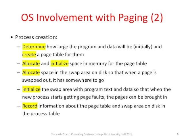
OS Involvement with Paging (2)
Process creation:
Determine how large the program and
OS Involvement with Paging (2)
Process creation:
Determine how large the program and
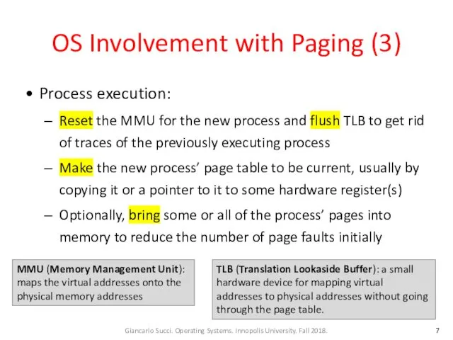
OS Involvement with Paging (3)
Process execution:
Reset the MMU for the new
OS Involvement with Paging (3)
Process execution:
Reset the MMU for the new
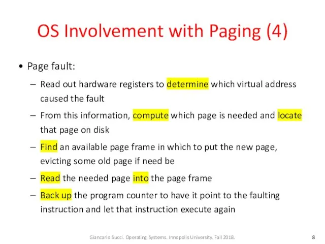
OS Involvement with Paging (4)
Page fault:
Read out hardware registers to determine
OS Involvement with Paging (4)
Page fault:
Read out hardware registers to determine
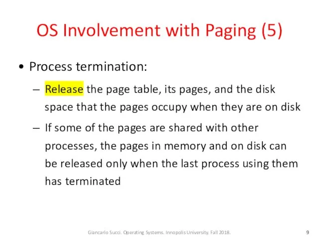
OS Involvement with Paging (5)
Process termination:
Release the page table, its pages,
OS Involvement with Paging (5)
Process termination:
Release the page table, its pages,
Page Fault Handling (1)
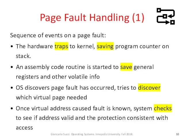
Sequence of events on a page fault:
The hardware
Page Fault Handling (1)
Sequence of events on a page fault:
The hardware
Page Fault Handling (2)
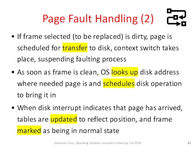
If frame selected (to be replaced) is dirty,
Page Fault Handling (2)
If frame selected (to be replaced) is dirty,
Page Fault Handling (3)
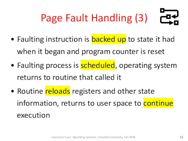
Faulting instruction is backed up to state it
Page Fault Handling (3)
Faulting instruction is backed up to state it
Instruction Backup (1)
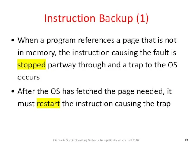
When a program references a page that is not
Instruction Backup (1)
When a program references a page that is not
Instruction Backup (2)
Let’s consider a CPU which is used in embedded
Instruction Backup (2)
Let’s consider a CPU which is used in embedded
Instruction Backup (3)
The instruction starts at address 1000 and makes three
Instruction Backup (3)
The instruction starts at address 1000 and makes three
Instruction Backup (4)
In our case the program counter might be 1000,
Instruction Backup (4)
In our case the program counter might be 1000,
Instruction Backup (5)
Some addressing modes use autoincrementing: one or more registers
Instruction Backup (5)
Some addressing modes use autoincrementing: one or more registers
Instruction Backup (6)
A possible solution is to have a hidden internal
Instruction Backup (6)
A possible solution is to have a hidden internal
Locking Pages in Memory (1)
Consider a process that has just issued
Locking Pages in Memory (1)
Consider a process that has just issued
Locking Pages in Memory (2)
If the paging algorithm is global, there
Locking Pages in Memory (2)
If the paging algorithm is global, there
Locking Pages in Memory (3)
One solution to this problem is to
Locking Pages in Memory (3)
One solution to this problem is to
Backing Store (1)
Where on disk a page selected for replacement is
Backing Store (1)
Where on disk a page selected for replacement is
Backing Store (2)
When the system is booted, this swap partition is
Backing Store (2)
When the system is booted, this swap partition is
Backing Store (3)
Each process has associated to it a disk address
Backing Store (3)
Each process has associated to it a disk address
Backing Store (4)
The processes can increase in size after they start.
Backing Store (4)
The processes can increase in size after they start.
Backing Store (5)
Figure 3-28. (a) Paging to a static swap area.
Backing Store (5)
Figure 3-28. (a) Paging to a static swap area.
Backing Store (6)
Having a fixed swap partition is not always possible.
Backing Store (6)
Having a fixed swap partition is not always possible.
Separation of Policy and Mechanism (1)
Tool for managing the complexity of
Separation of Policy and Mechanism (1)
Tool for managing the complexity of
Separation of Policy and Mechanism (2)
Figure 3-29. Page fault handling with
Separation of Policy and Mechanism (2)
Figure 3-29. Page fault handling with
Separation of Policy and Mechanism (3)
All the details of how the
Separation of Policy and Mechanism (3)
All the details of how the
Separation of Policy and Mechanism (4)
When a process starts up, the
Separation of Policy and Mechanism (4)
When a process starts up, the
Separation of Policy and Mechanism (5)
Figure 3-29. Page fault handling with
Separation of Policy and Mechanism (5)
Figure 3-29. Page fault handling with
Separation of Policy and Mechanism (6)
2. The fault handler figures out
Separation of Policy and Mechanism (6)
2. The fault handler figures out
Separation of Policy and Mechanism (7)
3. The external pager reads the
Separation of Policy and Mechanism (7)
3. The external pager reads the
Separation of Policy and Mechanism (8)
5. The external pager informs the
Separation of Policy and Mechanism (8)
5. The external pager informs the
Separation of Policy and Mechanism (9)
6. The fault handler unmaps the
Separation of Policy and Mechanism (9)
6. The fault handler unmaps the
Separation of Policy and Mechanism (10)
The page replacement algorithm can be
Separation of Policy and Mechanism (10)
The page replacement algorithm can be
Separation of Policy and Mechanism (11)
The main advantage of this implementation
Separation of Policy and Mechanism (11)
The main advantage of this implementation
Segmentation (1)
Examples of several tables generated by compiler:
The source text being
Segmentation (1)
Examples of several tables generated by compiler:
The source text being
Segmentation (2)
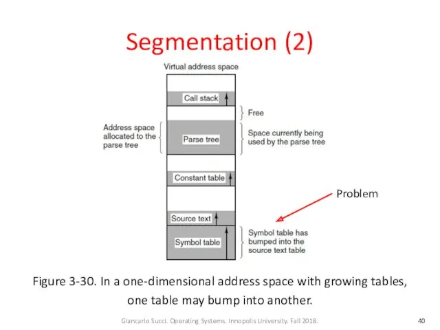
Figure 3-30. In a one-dimensional address space with growing tables,
Segmentation (2)
Figure 3-30. In a one-dimensional address space with growing tables,
Segmentation (3)
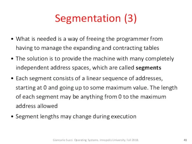
What is needed is a way of freeing the programmer
Segmentation (3)
What is needed is a way of freeing the programmer
Segmentation (4)
Because each segment constitutes a separate address space, different segments
Segmentation (4)
Because each segment constitutes a separate address space, different segments
Segmentation (5)
Figure 3-31. A segmented memory allows each table to grow
Segmentation (5)
Figure 3-31. A segmented memory allows each table to grow
Segmentation (6)
A segment is a logical entity that might contain a
Segmentation (6)
A segment is a logical entity that might contain a
Segmentation (7)
Advantages of segments (cont.):
If the procedure in segment n is
Segmentation (7)
Advantages of segments (cont.):
If the procedure in segment n is
Segmentation (8)
Figure 3-32. Comparison of paging and segmentation
Segmentation (8)
Figure 3-32. Comparison of paging and segmentation
Segmentation (9)
Figure 3-32. Comparison of paging and segmentation
Segmentation (9)
Figure 3-32. Comparison of paging and segmentation
Implementation of
Pure Segmentation (1)
Consider a piece of memory containing five
Implementation of
Pure Segmentation (1)
Consider a piece of memory containing five
Implementation of
Pure Segmentation (2)
Figure 3-33. (a)-(d) Development of checkerboarding.
(e)
Implementation of
Pure Segmentation (2)
Figure 3-33. (a)-(d) Development of checkerboarding. (e)
Segmentation with Paging
If the segments are large, it may be inconvenient
Segmentation with Paging
If the segments are large, it may be inconvenient
Segmentation with Paging: MULTICS (1)
MULTICS ran on the Honeywell 6000 machines
Segmentation with Paging: MULTICS (1)
MULTICS ran on the Honeywell 6000 machines
Segmentation with Paging: MULTICS (2)
Each MULTICS program had a segment table,
Segmentation with Paging: MULTICS (2)
Each MULTICS program had a segment table,
Segmentation with Paging: MULTICS (3)
Figure 3-34a. The descriptor segment pointed to
Segmentation with Paging: MULTICS (3)
Figure 3-34a. The descriptor segment pointed to
Segmentation with Paging: MULTICS (4)
Physical addresses were 24 bits and pages
Segmentation with Paging: MULTICS (4)
Physical addresses were 24 bits and pages
Segmentation with Paging: MULTICS (5)
Figure 3-34. A segment descriptor.
The numbers
Segmentation with Paging: MULTICS (5)
Figure 3-34. A segment descriptor.
The numbers
Segmentation with Paging: MULTICS (6)
Each segment was an ordinary virtual address
Segmentation with Paging: MULTICS (6)
Each segment was an ordinary virtual address
Segmentation with Paging: MULTICS (7)
Figure 3-35. A 34-bit MULTICS virtual address.
Segmentation with Paging: MULTICS (7)
Figure 3-35. A 34-bit MULTICS virtual address.
Segmentation with Paging: MULTICS (8)
When a memory reference occurred, the following
Segmentation with Paging: MULTICS (8)
When a memory reference occurred, the following
Segmentation with Paging: MULTICS (9)
Memory reference with segments (cont.):
The page table
Segmentation with Paging: MULTICS (9)
Memory reference with segments (cont.):
The page table
Segmentation with Paging: MULTICS (10)
Figure 3-36. Conversion of a two-part MULTICS
Segmentation with Paging: MULTICS (10)
Figure 3-36. Conversion of a two-part MULTICS
Segmentation with Paging: MULTICS (11)
The MULTICS hardware contained a 16-word high-speed
Segmentation with Paging: MULTICS (11)
The MULTICS hardware contained a 16-word high-speed
Segmentation with Paging: MULTICS (12)
Figure 3-37. A simplified version of the
Segmentation with Paging: MULTICS (12)
Figure 3-37. A simplified version of the
Segmentation with Paging:
The Intel x86 (1)
In x86-64 CPUs, segmentation is
Segmentation with Paging:
The Intel x86 (1)
In x86-64 CPUs, segmentation is
Segmentation with Paging:
The Intel x86 (2)
x86 virtual memory model contains
Segmentation with Paging:
The Intel x86 (2)
x86 virtual memory model contains
Segmentation with Paging:
The Intel x86 (3)
To access a segment, an
Segmentation with Paging:
The Intel x86 (3)
To access a segment, an
Segmentation with Paging:
The Intel x86 (4)
Figure 3-38. An x86 selector.
Segmentation with Paging:
The Intel x86 (4)
Figure 3-38. An x86 selector.
Segmentation with Paging:
The Intel x86 (5)
At the time a selector
Segmentation with Paging:
The Intel x86 (5)
At the time a selector
Segmentation with Paging:
The Intel x86 (6)
Figure 3-39. x86 code segment
Segmentation with Paging:
The Intel x86 (6)
Figure 3-39. x86 code segment
Segmentation with Paging:
The Intel x86 (7)
Step-by-step conversion of a (selector,
Segmentation with Paging:
The Intel x86 (7)
Step-by-step conversion of a (selector,
Segmentation with Paging:
The Intel x86 (7)
Conversion (cont.):
If the Gbit (Granularity)
Segmentation with Paging:
The Intel x86 (7)
Conversion (cont.):
If the Gbit (Granularity)
Segmentation with Paging:
The Intel x86 (8)
Figure 3-40. Conversion of a
Segmentation with Paging:
The Intel x86 (8)
Figure 3-40. Conversion of a
Segmentation with Paging:
The Intel x86 (9)
Conversion (cont.):
If paging is enabled,
Segmentation with Paging:
The Intel x86 (9)
Conversion (cont.):
If paging is enabled,
Segmentation with Paging:
The Intel x86 (10)
Conversion (cont.):
The Dir field of
Segmentation with Paging:
The Intel x86 (10)
Conversion (cont.):
The Dir field of
Segmentation with Paging:
The Intel x86 (11)
Figure 3-41. Linear to physical
Segmentation with Paging:
The Intel x86 (11)
Figure 3-41. Linear to physical
Week 09 – Lecture 1
End
Week 09 – Lecture 1
End
 Информационные технологии в науке и образовании
 Разработка и создание приложения на Delphi Расписание занятий техникума
 Информационная система
 Проектная технология на уроках информатики
 Разработка и установка мобильного приложения
 Графика. Графический режим
 Бит чётности
 Занятия 9-10. Требования с точки зрения РКЗ
 Медицинские информационные системы классификация, цели, принципы использования, достоинства, недостатки, основные пути развития
 Показатели защищенности средств вычислительной техники. Основы информационной безопасности
 Интернет-сленг
 Новые информационные технологии. Понятие информационной технологии как составной части информатики
 Примеры онтологий (онтология вин и пищи)
 Моделирование, как метод познания. Типы информационных моделей
 Решение логических задач табличным способом
 Система программирования - система для разработки новых программ на конкретном языке программирования
 Среда программирования на ЯП Паскаль
 Отчет Работа с современным инновационным учебным оборудованием
 Задача коммивояжера
 Использование информационно-коммуникационных технологий на уроках английского языка
 Защита персональных данных. Угрозы в области технической защиты информации. Оценка рисков
 Техническая оптимизация сайта. Ошибки кода и верстки
 Основные понятия базы данных
 Професія - графічний дизайнер
 Представление чисел в компьютере
 السلام عليكم ايها المشاهدون
 Техзадание к сайту
 урок информатики на тему: Устройства ввода-вывода информации. 8 класс