- Module 9: The Transport Layer

Содержание
- 2. Instructor Materials – Module 9 Planning Guide This PowerPoint deck is divided in two parts: Instructor
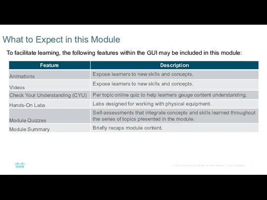
- 3. What to Expect in this Module To facilitate learning, the following features within the GUI may
- 4. Check Your Understanding Check Your Understanding activities are designed to let students quickly determine if they
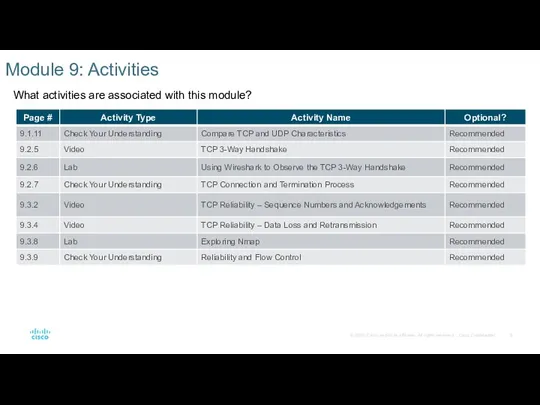
- 5. Module 9: Activities What activities are associated with this module?
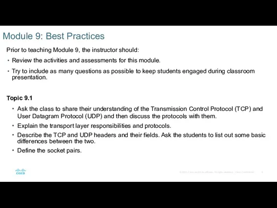
- 6. Module 9: Best Practices Prior to teaching Module 9, the instructor should: Review the activities and
- 7. Module 9: Best Practices (Contd.) Topic 9.2 Explain the TCP server processes to the class. Describe
- 8. CyberOps Associate v1.0 Module 9: The Transport Layer
- 9. Module Objectives Module Title: The Transport Layer Module Objective: Explain how transport layer protocols support network
- 10. 9.1 Transport Layer Characteristics
- 11. The Transport Layer Role of the Transport Layer The transport layer is responsible for logical communications
- 12. The Transport Layer Transport Layer Responsibilities The transport layer has many responsibilities. Tracking Individual Conversations Each
- 13. The Transport Layer Transport Layer Responsibilities (Contd.) Segmenting Data and Reassembling Segments It is the transport
- 14. The Transport Layer Transport Layer Responsibilities (Contd.) Add Header Information The transport layer protocol also adds
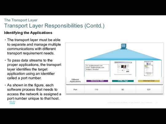
- 15. The Transport Layer Transport Layer Responsibilities (Contd.) Identifying the Applications The transport layer must be able
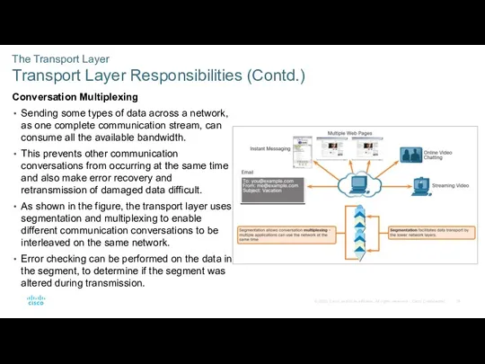
- 16. The Transport Layer Transport Layer Responsibilities (Contd.) Conversation Multiplexing Sending some types of data across a
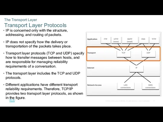
- 17. The Transport Layer Transport Layer Protocols IP is concerned only with the structure, addressing, and routing
- 18. The Transport Layer Transmission Control Protocol (TCP) TCP is considered a reliable, full-featured transport layer protocol,
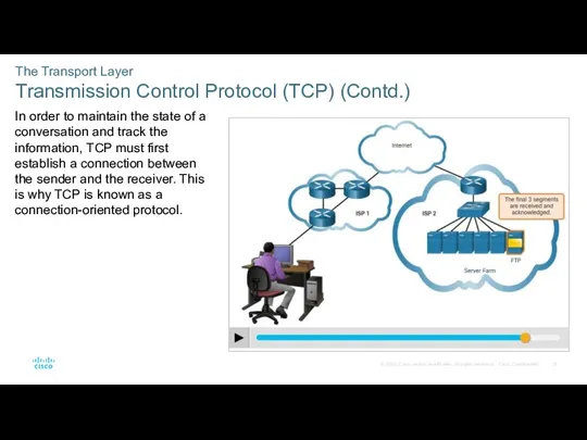
- 19. The Transport Layer Transmission Control Protocol (TCP) (Contd.) In order to maintain the state of a
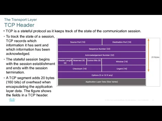
- 20. The Transport Layer TCP Header TCP is a stateful protocol as it keeps track of the
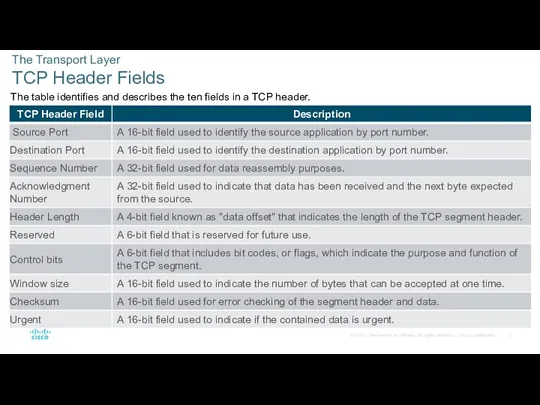
- 21. The Transport Layer TCP Header Fields The table identifies and describes the ten fields in a
- 22. The Transport Layer User Datagram Protocol (UDP) UDP is a simpler transport layer protocol than TCP.
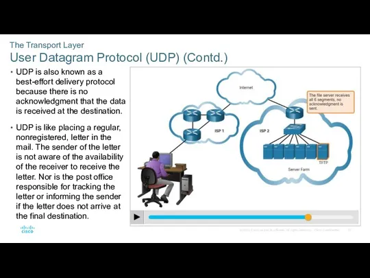
- 23. The Transport Layer User Datagram Protocol (UDP) (Contd.) UDP is also known as a best-effort delivery
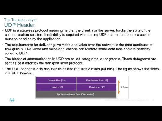
- 24. The Transport Layer UDP Header UDP is a stateless protocol meaning neither the client, nor the
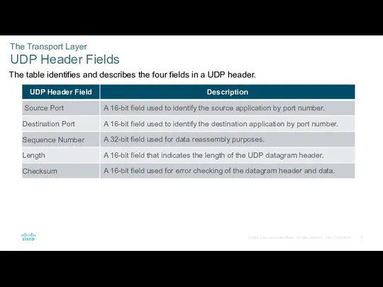
- 25. The Transport Layer UDP Header Fields The table identifies and describes the four fields in a
- 26. The Transport Layer Socket Pairs The source and destination ports are placed within the segment. The
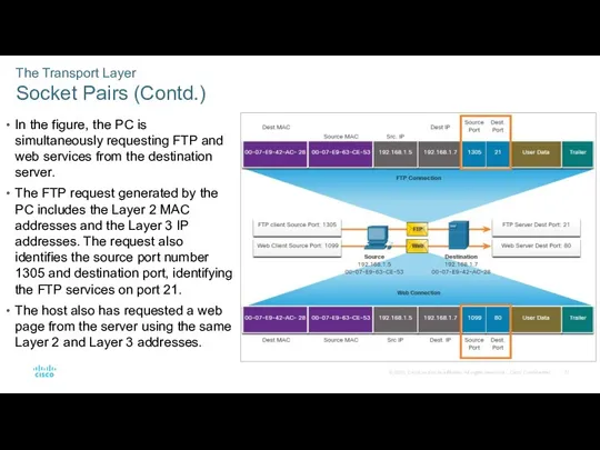
- 27. The Transport Layer Socket Pairs (Contd.) In the figure, the PC is simultaneously requesting FTP and
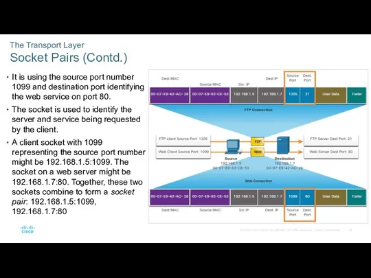
- 28. The Transport Layer Socket Pairs (Contd.) It is using the source port number 1099 and destination
- 29. 9.2 Transport Layer Session Establishment
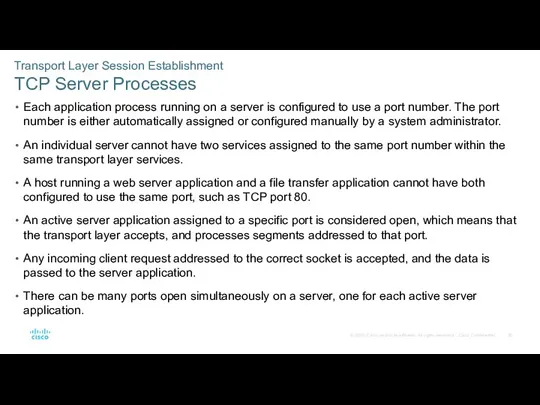
- 30. Transport Layer Session Establishment TCP Server Processes Each application process running on a server is configured
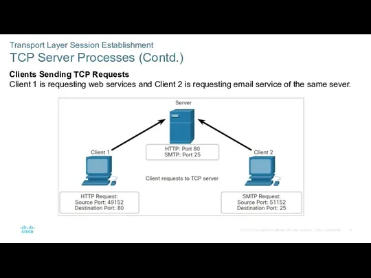
- 31. Transport Layer Session Establishment TCP Server Processes (Contd.) Clients Sending TCP Requests Client 1 is requesting
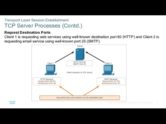
- 32. Transport Layer Session Establishment TCP Server Processes (Contd.) Request Destination Ports Client 1 is requesting web
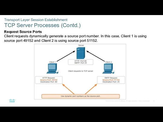
- 33. Transport Layer Session Establishment TCP Server Processes (Contd.) Request Source Ports Client requests dynamically generate a
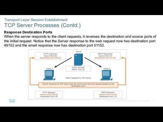
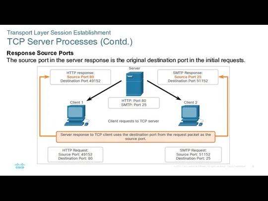
- 34. Transport Layer Session Establishment TCP Server Processes (Contd.) Response Destination Ports When the server responds to
- 35. Transport Layer Session Establishment TCP Server Processes (Contd.) Response Source Ports The source port in the
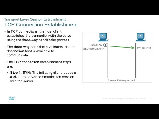
- 36. Transport Layer Session Establishment TCP Connection Establishment In TCP connections, the host client establishes the connection
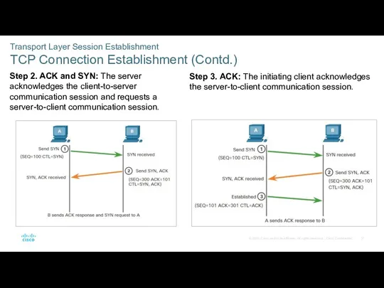
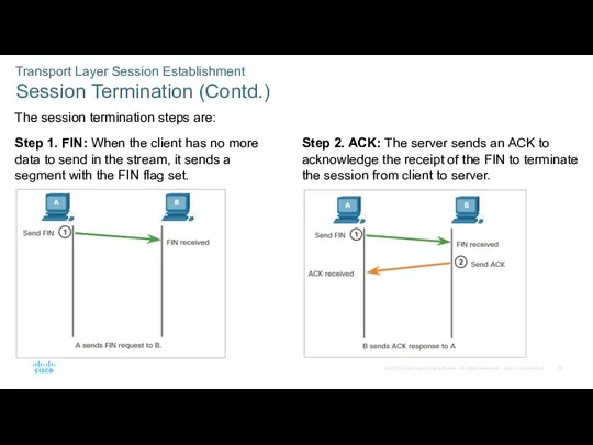
- 37. Transport Layer Session Establishment TCP Connection Establishment (Contd.) Step 2. ACK and SYN: The server acknowledges
- 38. Transport Layer Session Establishment Session Termination To close a connection, the Finish (FIN) control flag must
- 39. Transport Layer Session Establishment Session Termination (Contd.) The session termination steps are: Step 1. FIN: When
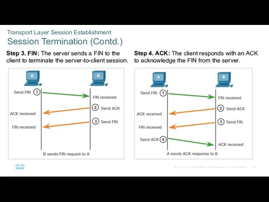
- 40. Transport Layer Session Establishment Session Termination (Contd.) Step 3. FIN: The server sends a FIN to
- 41. Transport Layer Session Establishment TCP Three-way Handshake Analysis Hosts maintain state, track each data segment within
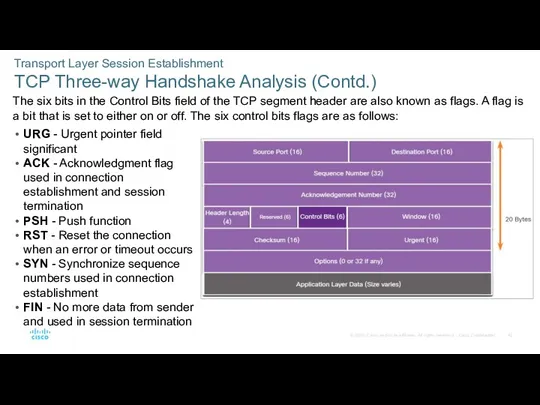
- 42. Transport Layer Session Establishment TCP Three-way Handshake Analysis (Contd.) The six bits in the Control Bits
- 43. Transport Layer Session Establishment Video – TCP 3-Way Handshake Watch the video to learn more of
- 44. Transport Layer Session Establishment Lab – Using Wireshark to Observe the TCP 3-Way Handshake In this
- 45. 9.3 Transport Layer Reliability
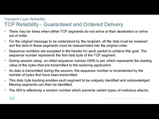
- 46. Transport Layer Reliability TCP Reliability - Guaranteed and Ordered Delivery There may be times when either
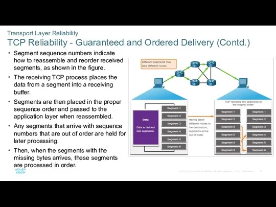
- 47. Transport Layer Reliability TCP Reliability - Guaranteed and Ordered Delivery (Contd.) Segment sequence numbers indicate how
- 48. Transport Layer Reliability Video - TCP Reliability – Sequence Numbers and Acknowledgements One of the functions
- 49. Transport Layer Reliability TCP Reliability - Data Loss and Retransmission TCP provides methods of managing the
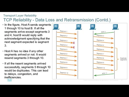
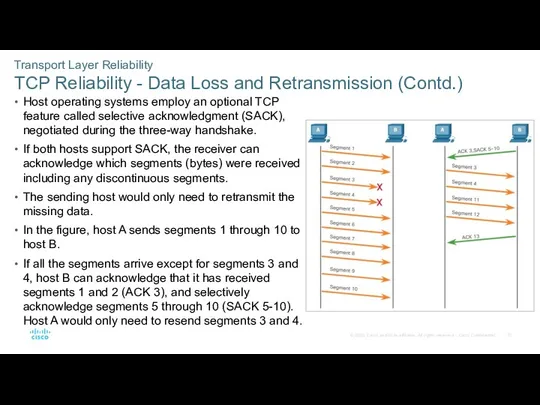
- 50. Transport Layer Reliability TCP Reliability - Data Loss and Retransmission (Contd.) In the figure, Host A
- 51. Transport Layer Reliability TCP Reliability - Data Loss and Retransmission (Contd.) Host operating systems employ an
- 52. Transport Layer Reliability Video - TCP Reliability - Data Loss and Retransmission Click Play in the
- 53. Transport Layer Reliability TCP Flow Control - Window Size and Acknowledgments TCP also provides mechanisms for
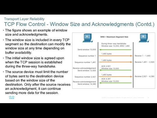
- 54. Transport Layer Reliability TCP Flow Control - Window Size and Acknowledgments (Contd.) The figure shows an
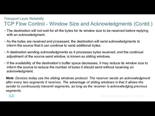
- 55. Transport Layer Reliability TCP Flow Control - Window Size and Acknowledgments (Contd.) The destination will not
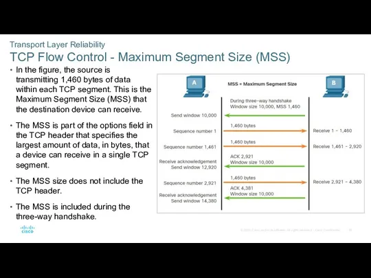
- 56. Transport Layer Reliability TCP Flow Control - Maximum Segment Size (MSS) In the figure, the source
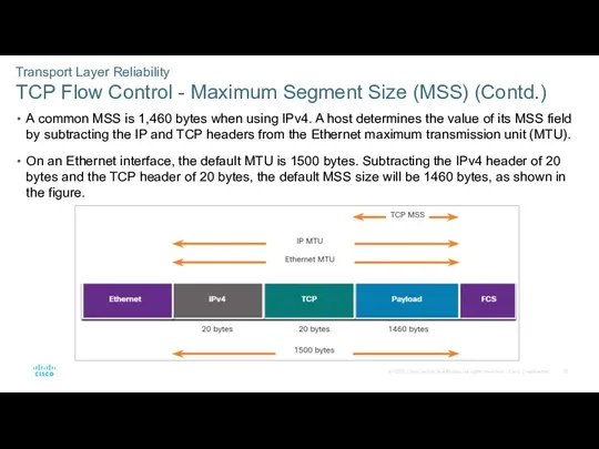
- 57. Transport Layer Reliability TCP Flow Control - Maximum Segment Size (MSS) (Contd.) A common MSS is
- 58. Transport Layer Reliability TCP Flow Control - Congestion Avoidance When congestion occurs on a network, it
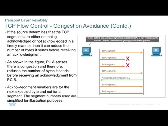
- 59. Transport Layer Reliability TCP Flow Control - Congestion Avoidance (Contd.) If the source determines that the
- 60. Transport Layer Reliability Lab – Exploring Nmap Port scanning is usually part of a reconnaissance attack.
- 61. 9.4 The Transport Layer Summary
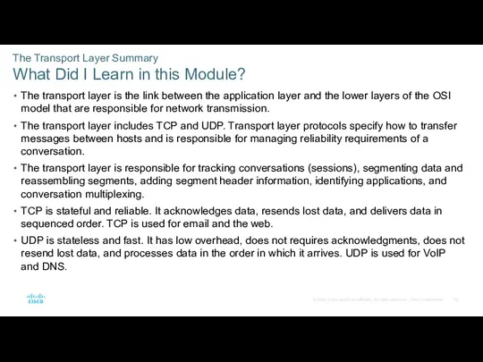
- 62. The Transport Layer Summary What Did I Learn in this Module? The transport layer is the
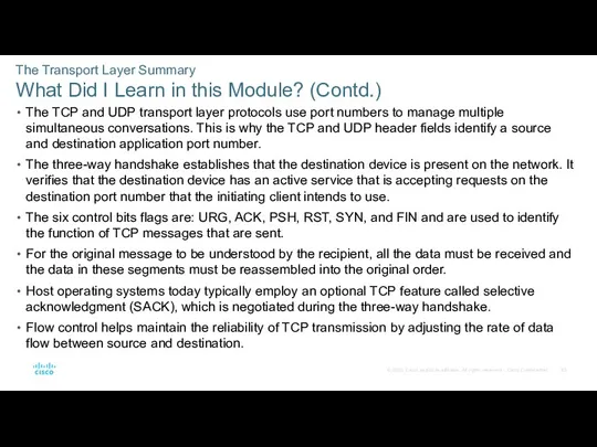
- 63. The Transport Layer Summary What Did I Learn in this Module? (Contd.) The TCP and UDP
- 64. Module 9 New Terms and Commands
- 66. Скачать презентацию
Instructor Materials – Module 9 Planning Guide
This PowerPoint deck is divided
Instructor Materials – Module 9 Planning Guide
This PowerPoint deck is divided
What to Expect in this Module
To facilitate learning, the following features
What to Expect in this Module
To facilitate learning, the following features

Check Your Understanding
Check Your Understanding activities are designed to let students
Check Your Understanding
Check Your Understanding activities are designed to let students
Module 9: Activities
What activities are associated with this module?
Module 9: Activities
What activities are associated with this module?
Module 9: Best Practices
Prior to teaching Module 9, the instructor should:
Review
Module 9: Best Practices
Prior to teaching Module 9, the instructor should:
Review
Module 9: Best Practices (Contd.)
Topic 9.2
Explain the TCP server processes to
Module 9: Best Practices (Contd.)
Topic 9.2
Explain the TCP server processes to
CyberOps Associate v1.0
Module 9: The Transport Layer
CyberOps Associate v1.0
Module 9: The Transport Layer
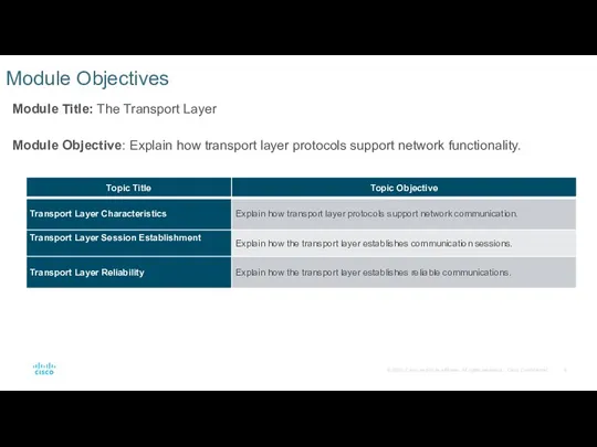
Module Objectives
Module Title: The Transport Layer
Module Objective: Explain how transport layer
Module Objectives
Module Title: The Transport Layer
Module Objective: Explain how transport layer
9.1 Transport Layer Characteristics
9.1 Transport Layer Characteristics
The Transport Layer
Role of the Transport Layer
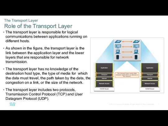
The transport layer is responsible
The Transport Layer
Role of the Transport Layer
The transport layer is responsible
The Transport Layer
Transport Layer Responsibilities
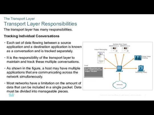
The transport layer has many responsibilities.
Tracking Individual
The Transport Layer
Transport Layer Responsibilities
The transport layer has many responsibilities.
Tracking Individual
The Transport Layer
Transport Layer Responsibilities (Contd.)
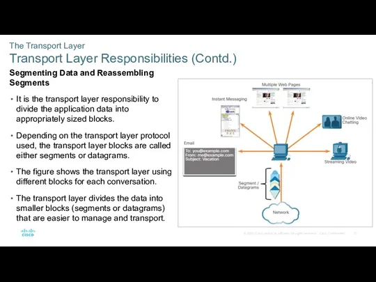
Segmenting Data and Reassembling Segments
It is
The Transport Layer
Transport Layer Responsibilities (Contd.)
Segmenting Data and Reassembling Segments
It is
The Transport Layer
Transport Layer Responsibilities (Contd.)
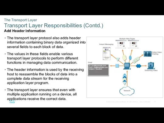
Add Header Information
The transport layer protocol
The Transport Layer
Transport Layer Responsibilities (Contd.)
Add Header Information
The transport layer protocol
The Transport Layer
Transport Layer Responsibilities (Contd.)
Identifying the Applications
The transport layer must
The Transport Layer
Transport Layer Responsibilities (Contd.)
Identifying the Applications
The transport layer must
The Transport Layer
Transport Layer Responsibilities (Contd.)
Conversation Multiplexing
Sending some types of data
The Transport Layer
Transport Layer Responsibilities (Contd.)
Conversation Multiplexing
Sending some types of data
The Transport Layer
Transport Layer Protocols
IP is concerned only with the structure,
The Transport Layer
Transport Layer Protocols
IP is concerned only with the structure,
The Transport Layer
Transmission Control Protocol (TCP)
TCP is considered a reliable, full-featured
The Transport Layer
Transmission Control Protocol (TCP)
TCP is considered a reliable, full-featured
The Transport Layer
Transmission Control Protocol (TCP) (Contd.)
In order to maintain the
The Transport Layer
Transmission Control Protocol (TCP) (Contd.)
In order to maintain the
The Transport Layer
TCP Header
TCP is a stateful protocol as it keeps
The Transport Layer
TCP Header
TCP is a stateful protocol as it keeps
The Transport Layer
TCP Header Fields
The table identifies and describes the ten
The Transport Layer
TCP Header Fields
The table identifies and describes the ten
The Transport Layer
User Datagram Protocol (UDP)
UDP is a simpler transport layer
The Transport Layer
User Datagram Protocol (UDP)
UDP is a simpler transport layer
The Transport Layer
User Datagram Protocol (UDP) (Contd.)
UDP is also known as
The Transport Layer
User Datagram Protocol (UDP) (Contd.)
UDP is also known as
The Transport Layer
UDP Header
UDP is a stateless protocol meaning neither the
The Transport Layer
UDP Header
UDP is a stateless protocol meaning neither the
The Transport Layer
UDP Header Fields
The table identifies and describes the four
The Transport Layer
UDP Header Fields
The table identifies and describes the four
The Transport Layer
Socket Pairs
The source and destination ports are placed within
The Transport Layer
Socket Pairs
The source and destination ports are placed within
The Transport Layer
Socket Pairs (Contd.)
In the figure, the PC is simultaneously
The Transport Layer
Socket Pairs (Contd.)
In the figure, the PC is simultaneously
The Transport Layer
Socket Pairs (Contd.)
It is using the source port number
The Transport Layer
Socket Pairs (Contd.)
It is using the source port number
9.2 Transport Layer Session Establishment
9.2 Transport Layer Session Establishment
Transport Layer Session Establishment
TCP Server Processes
Each application process running on a
Transport Layer Session Establishment
TCP Server Processes
Each application process running on a
Transport Layer Session Establishment
TCP Server Processes (Contd.)
Clients Sending TCP Requests
Client 1
Transport Layer Session Establishment
TCP Server Processes (Contd.)
Clients Sending TCP Requests
Client 1
Transport Layer Session Establishment
TCP Server Processes (Contd.)
Request Destination Ports
Client 1 is
Transport Layer Session Establishment
TCP Server Processes (Contd.)
Request Destination Ports
Client 1 is
Transport Layer Session Establishment
TCP Server Processes (Contd.)
Request Source Ports
Client requests dynamically
Transport Layer Session Establishment
TCP Server Processes (Contd.)
Request Source Ports
Client requests dynamically
Transport Layer Session Establishment
TCP Server Processes (Contd.)
Response Destination Ports
When the server
Transport Layer Session Establishment
TCP Server Processes (Contd.)
Response Destination Ports
When the server
Transport Layer Session Establishment
TCP Server Processes (Contd.)
Response Source Ports
The source port
Transport Layer Session Establishment
TCP Server Processes (Contd.)
Response Source Ports
The source port
Transport Layer Session Establishment
TCP Connection Establishment
In TCP connections, the host client
Transport Layer Session Establishment
TCP Connection Establishment
In TCP connections, the host client
Transport Layer Session Establishment
TCP Connection Establishment (Contd.)
Step 2. ACK and SYN:
Transport Layer Session Establishment
TCP Connection Establishment (Contd.)
Step 2. ACK and SYN:
Transport Layer Session Establishment
Session Termination
To close a connection, the Finish (FIN)
Transport Layer Session Establishment
Session Termination
To close a connection, the Finish (FIN)
Transport Layer Session Establishment
Session Termination (Contd.)
The session termination steps are:
Step 1.
Transport Layer Session Establishment
Session Termination (Contd.)
The session termination steps are:
Step 1.
Transport Layer Session Establishment
Session Termination (Contd.)
Step 3. FIN: The server sends
Transport Layer Session Establishment
Session Termination (Contd.)
Step 3. FIN: The server sends
Transport Layer Session Establishment
TCP Three-way Handshake Analysis
Hosts maintain state, track each
Transport Layer Session Establishment
TCP Three-way Handshake Analysis
Hosts maintain state, track each
Transport Layer Session Establishment
TCP Three-way Handshake Analysis (Contd.)
The six bits in
Transport Layer Session Establishment
TCP Three-way Handshake Analysis (Contd.)
The six bits in
Transport Layer Session Establishment
Video – TCP 3-Way Handshake
Watch the video to
Transport Layer Session Establishment
Video – TCP 3-Way Handshake
Watch the video to
Transport Layer Session Establishment
Lab – Using Wireshark to Observe the TCP
Transport Layer Session Establishment Lab – Using Wireshark to Observe the TCP
9.3 Transport Layer Reliability
9.3 Transport Layer Reliability
Transport Layer Reliability
TCP Reliability - Guaranteed and Ordered Delivery
There may be
Transport Layer Reliability
TCP Reliability - Guaranteed and Ordered Delivery
There may be
Transport Layer Reliability
TCP Reliability - Guaranteed and Ordered Delivery (Contd.)
Segment sequence
Transport Layer Reliability
TCP Reliability - Guaranteed and Ordered Delivery (Contd.)
Segment sequence
Transport Layer Reliability
Video - TCP Reliability – Sequence Numbers and Acknowledgements
One
Transport Layer Reliability
Video - TCP Reliability – Sequence Numbers and Acknowledgements
One
Transport Layer Reliability
TCP Reliability - Data Loss and Retransmission
TCP provides methods
Transport Layer Reliability
TCP Reliability - Data Loss and Retransmission
TCP provides methods
Transport Layer Reliability
TCP Reliability - Data Loss and Retransmission (Contd.)
In the
Transport Layer Reliability
TCP Reliability - Data Loss and Retransmission (Contd.)
In the
Transport Layer Reliability
TCP Reliability - Data Loss and Retransmission (Contd.)
Host operating
Transport Layer Reliability
TCP Reliability - Data Loss and Retransmission (Contd.)
Host operating
Transport Layer Reliability
Video - TCP Reliability - Data Loss and Retransmission
Click
Transport Layer Reliability
Video - TCP Reliability - Data Loss and Retransmission
Click
Transport Layer Reliability
TCP Flow Control - Window Size and Acknowledgments
TCP also
Transport Layer Reliability
TCP Flow Control - Window Size and Acknowledgments
TCP also
Transport Layer Reliability
TCP Flow Control - Window Size and Acknowledgments (Contd.)
The
Transport Layer Reliability
TCP Flow Control - Window Size and Acknowledgments (Contd.)
The
Transport Layer Reliability
TCP Flow Control - Window Size and Acknowledgments (Contd.)
The
Transport Layer Reliability
TCP Flow Control - Window Size and Acknowledgments (Contd.)
The
Transport Layer Reliability
TCP Flow Control - Maximum Segment Size (MSS)
In the
Transport Layer Reliability
TCP Flow Control - Maximum Segment Size (MSS)
In the
Transport Layer Reliability
TCP Flow Control - Maximum Segment Size (MSS) (Contd.)
A
Transport Layer Reliability
TCP Flow Control - Maximum Segment Size (MSS) (Contd.)
A

Transport Layer Reliability
TCP Flow Control - Congestion Avoidance
When congestion occurs on
Transport Layer Reliability
TCP Flow Control - Congestion Avoidance
When congestion occurs on
Transport Layer Reliability
TCP Flow Control - Congestion Avoidance (Contd.)
If the source
Transport Layer Reliability
TCP Flow Control - Congestion Avoidance (Contd.)
If the source
Transport Layer Reliability
Lab – Exploring Nmap
Port scanning is usually part of
Transport Layer Reliability
Lab – Exploring Nmap
Port scanning is usually part of
9.4 The Transport Layer Summary
9.4 The Transport Layer Summary
The Transport Layer Summary
What Did I Learn in this Module?
The transport
The Transport Layer Summary
What Did I Learn in this Module?
The transport
The Transport Layer Summary
What Did I Learn in this Module? (Contd.)
The
The Transport Layer Summary
What Did I Learn in this Module? (Contd.)
The
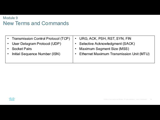
Module 9
New Terms and Commands
Module 9
New Terms and Commands
 Проблемы анализа данных в медико-биологических исследованиях. StatSoft Russia
 Autodesk inventor система автоматизированного проектирования. Работа в режиме Экскиз. Основные группы команд
 Файлы и файловые структуры. Компьютер как универсальное устройство для работы с информацией. Информатика. 7 класс
 Математический аппарат для проектирования компьютерных сетей. Нахождение эйлеровых циклов и путей
 Алгоритмы и модели трассировки проводных соединений в ЭА. Лекция 4
 Возможности динамических (электронных) таблиц
 Программирование многоядерных архитектур
 Электронный учебный курс
 Урок Двоичная система счисления
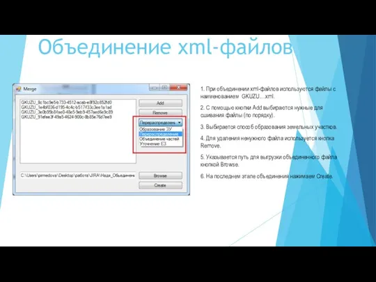 Инструкция к PackMerge
 СМИ. Газета. Журналы. Радио. Телевидение. Интернет
 Создание газеты в программе Microsoft Office Publisher
 Основные компоненты языка Ассемблер
 Функциональное тестирование
 Что представляет собой термин мультимедиа технология?
 1С-Рарус: Управление санаторнокурортным комплексом,
 Классификация ИТ. Структура АИТ
 О проведении в октябре 2019 г. переписи населения
 Безопасность в интернете
 Информационные ресурсы интернета
 Защита от несанкционированного доступа к информации
 Облачные технологии в образовании
 Информационная безопасность. Общие принципы. (Лекция 2)
 Графический редактор
 Внеклассное мероприятие по информатике. Анаграммы
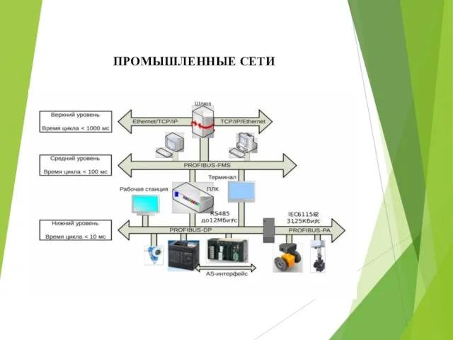 Промышленные сети
 История развития компьютеров
 Switch - оператор множественного выбора