- Network Layer: The Control Plane

Содержание
- 2. Chapter 5: network layer control plane chapter goals: understand principles behind network control plane traditional routing
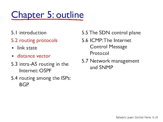
- 3. 5.1 introduction 5.2 routing protocols link state distance vector 5.3 intra-AS routing in the Internet: OSPF
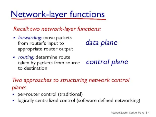
- 4. Network-layer functions forwarding: move packets from router’s input to appropriate router output data plane control plane
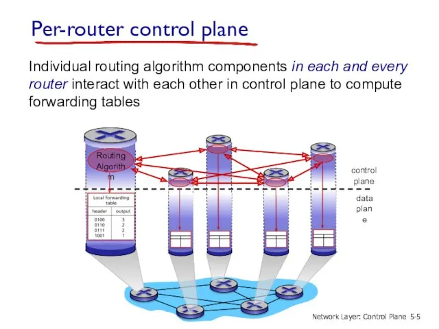
- 5. Per-router control plane Individual routing algorithm components in each and every router interact with each other
- 6. Logically centralized control plane A distinct (typically remote) controller interacts with local control agents (CAs) in
- 7. 5.1 introduction 5.2 routing protocols link state distance vector 5.3 intra-AS routing in the Internet: OSPF
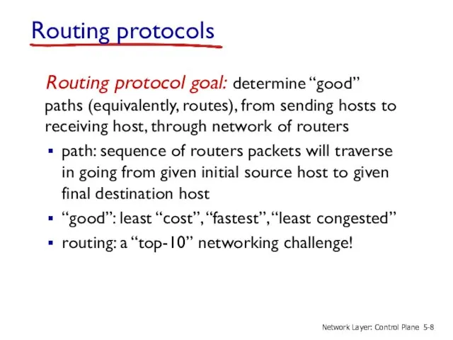
- 8. Routing protocols Routing protocol goal: determine “good” paths (equivalently, routes), from sending hosts to receiving host,
- 9. graph: G = (N,E) N = set of routers = { u, v, w, x, y,
- 10. Graph abstraction: costs c(x,x’) = cost of link (x,x’) e.g., c(w,z) = 5 cost could always
- 11. Routing algorithm classification Q: global or decentralized information? global: all routers have complete topology, link cost
- 12. 5.1 introduction 5.2 routing protocols link state distance vector 5.3 intra-AS routing in the Internet: OSPF
- 13. A link-state routing algorithm Dijkstra’s algorithm net topology, link costs known to all nodes accomplished via
- 14. Dijsktra’s algorithm 1 Initialization: 2 N' = {u} 3 for all nodes v 4 if v
- 15. Dijkstra’s algorithm: example Step N' D(v) p(v) 0 1 2 3 4 5 D(w) p(w) D(x)
- 16. Dijkstra’s algorithm: another example Step 0 1 2 3 4 5 N' u ux uxy uxyv
- 17. Dijkstra’s algorithm: example (2) resulting shortest-path tree from u: resulting forwarding table in u: 5- Network
- 18. Dijkstra’s algorithm, discussion algorithm complexity: n nodes each iteration: need to check all nodes, w, not
- 19. 5.1 introduction 5.2 routing protocols link state distance vector 5.3 intra-AS routing in the Internet: OSPF
- 20. Distance vector algorithm Bellman-Ford equation (dynamic programming) let dx(y) := cost of least-cost path from x
- 21. Bellman-Ford example clearly, dv(z) = 5, dx(z) = 3, dw(z) = 3 du(z) = min {
- 22. Distance vector algorithm Dx(y) = estimate of least cost from x to y x maintains distance
- 23. key idea: from time-to-time, each node sends its own distance vector estimate to neighbors when x
- 24. iterative, asynchronous: each local iteration caused by: local link cost change DV update message from neighbor
- 25. x y z x y z 0 2 7 ∞ ∞ ∞ ∞ ∞ ∞ from
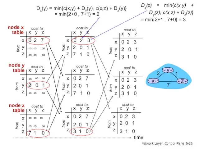
- 26. x y z x y z 0 2 3 from cost to x y z x
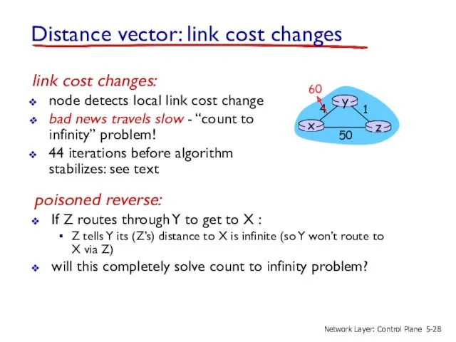
- 27. Distance vector: link cost changes link cost changes: node detects local link cost change updates routing
- 28. Distance vector: link cost changes link cost changes: node detects local link cost change bad news
- 29. Comparison of LS and DV algorithms message complexity LS: with n nodes, E links, O(nE) msgs
- 30. 5.1 introduction 5.2 routing protocols link state distance vector 5.3 intra-AS routing in the Internet: OSPF
- 31. Making routing scalable scale: with billions of destinations: can’t store all destinations in routing tables! routing
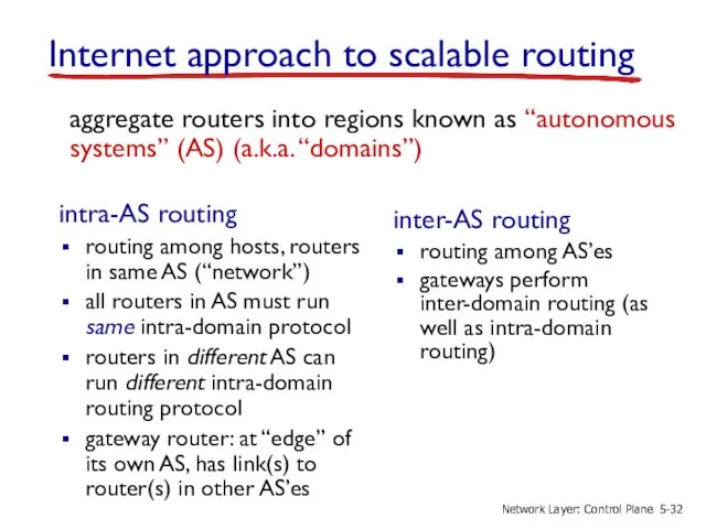
- 32. aggregate routers into regions known as “autonomous systems” (AS) (a.k.a. “domains”) inter-AS routing routing among AS’es
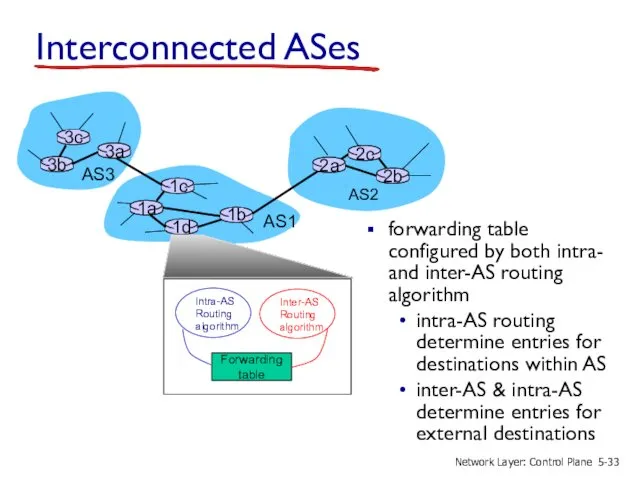
- 33. Interconnected ASes forwarding table configured by both intra- and inter-AS routing algorithm intra-AS routing determine entries
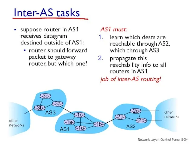
- 34. Inter-AS tasks suppose router in AS1 receives datagram destined outside of AS1: router should forward packet
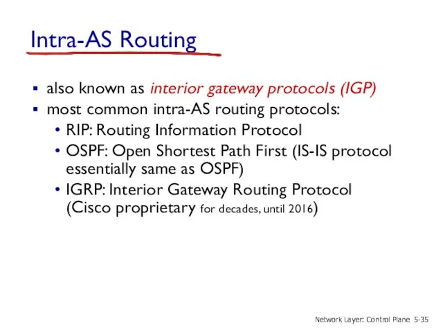
- 35. Intra-AS Routing also known as interior gateway protocols (IGP) most common intra-AS routing protocols: RIP: Routing
- 36. OSPF (Open Shortest Path First) “open”: publicly available uses link-state algorithm link state packet dissemination topology
- 37. OSPF “advanced” features security: all OSPF messages authenticated (to prevent malicious intrusion) multiple same-cost paths allowed
- 38. Hierarchical OSPF boundary router backbone router area 1 area 2 area 3 backbone area border routers
- 39. two-level hierarchy: local area, backbone. link-state advertisements only in area each nodes has detailed area topology;
- 40. 5.1 introduction 5.2 routing protocols link state distance vector 5.3 intra-AS routing in the Internet: OSPF
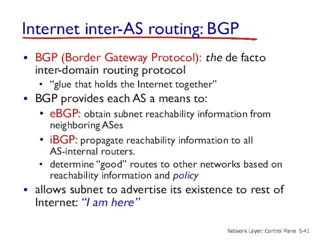
- 41. Internet inter-AS routing: BGP BGP (Border Gateway Protocol): the de facto inter-domain routing protocol “glue that
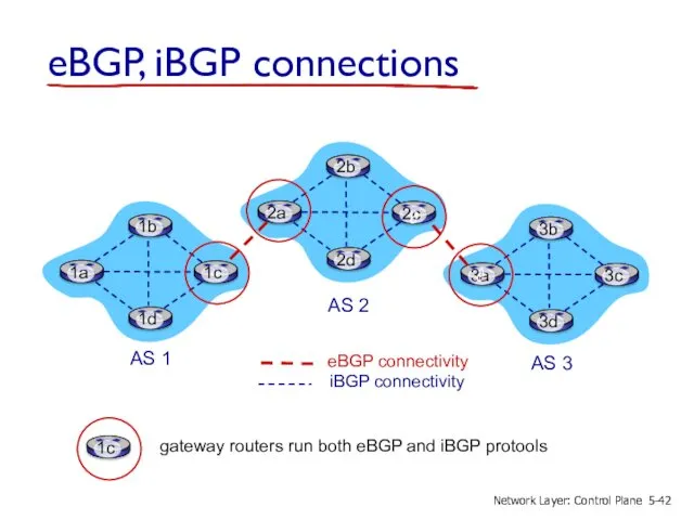
- 42. eBGP, iBGP connections AS 2 AS 3 AS 1 5- Network Layer: Control Plane
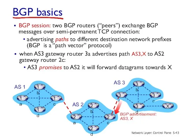
- 43. BGP basics when AS3 gateway router 3a advertises path AS3,X to AS2 gateway router 2c: AS3
- 44. Path attributes and BGP routes advertised prefix includes BGP attributes prefix + attributes = “route” two
- 45. BGP path advertisement Based on AS2 policy, AS2 router 2c accepts path AS3,X, propagates (via iBGP)
- 46. BGP path advertisement AS1 gateway router 1c learns path AS2,AS3,X from 2a AS2 AS3 AS1 gateway
- 47. BGP messages BGP messages exchanged between peers over TCP connection BGP messages: OPEN: opens TCP connection
- 48. BGP, OSPF, forwarding table entries recall: 1a, 1b, 1c learn about dest X via iBGP from
- 49. BGP, OSPF, forwarding table entries recall: 1a, 1b, 1c learn about dest X via iBGP from
- 50. BGP route selection router may learn about more than one route to destination AS, selects route
- 51. Hot Potato Routing 2d learns (via iBGP) it can route to X via 2a or 2c
- 52. A advertises path Aw to B and to C B chooses not to advertise BAw to
- 53. BGP: achieving policy via advertisements A,B,C are provider networks X,W,Y are customer (of provider networks) X
- 54. Why different Intra-, Inter-AS routing ? policy: inter-AS: admin wants control over how its traffic routed,
- 55. 5.1 introduction 5.2 routing protocols link state distance vector 5.3 intra-AS routing in the Internet: OSPF
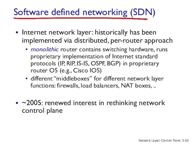
- 56. Software defined networking (SDN) Internet network layer: historically has been implemented via distributed, per-router approach monolithic
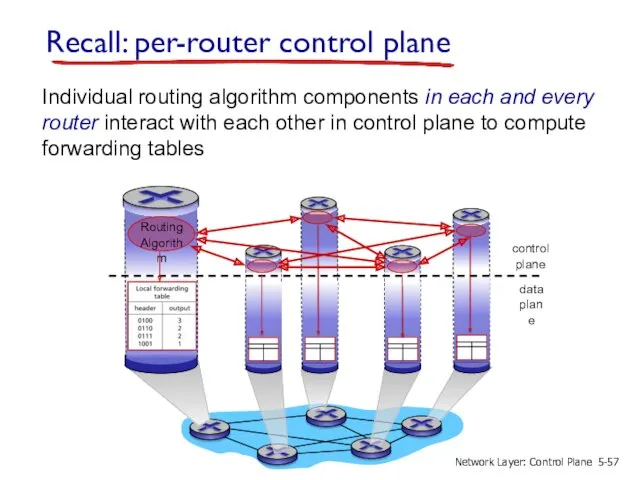
- 57. Recall: per-router control plane Individual routing algorithm components in each and every router interact with each
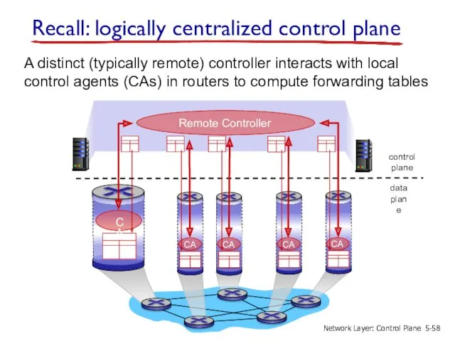
- 58. Recall: logically centralized control plane A distinct (typically remote) controller interacts with local control agents (CAs)
- 59. Software defined networking (SDN) Why a logically centralized control plane? easier network management: avoid router misconfigurations,
- 60. Vertically integrated Closed, proprietary Slow innovation Small industry Specialized Operating System Specialized Hardware Specialized Applications Horizontal
- 61. Traffic engineering: difficult traditional routing Q: what if network operator wants u-to-z traffic to flow along
- 62. Traffic engineering: difficult Q: what if network operator wants to split u-to-z traffic along uvwz and
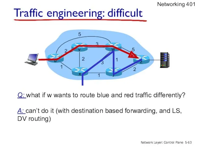
- 63. 2 2 1 3 1 1 2 5 3 5 Traffic engineering: difficult Q: what if
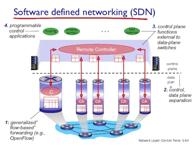
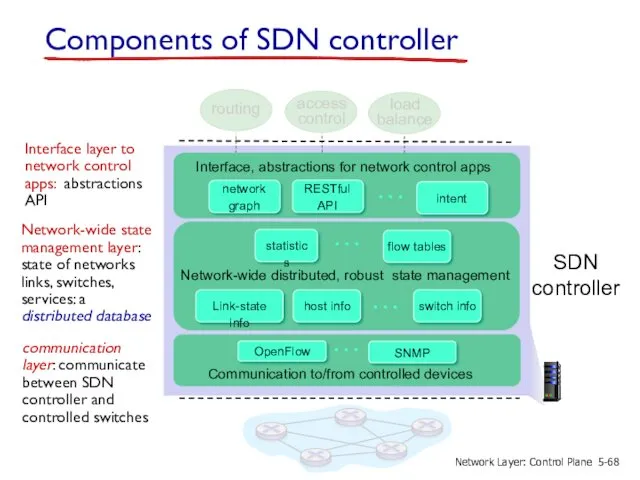
- 64. Software defined networking (SDN) 3. control plane functions external to data-plane switches … routing access control
- 65. SDN perspective: data plane switches Data plane switches fast, simple, commodity switches implementing generalized data-plane forwarding
- 66. SDN perspective: SDN controller SDN controller (network OS): maintain network state information interacts with network control
- 67. SDN perspective: control applications network-control apps: “brains” of control: implement control functions using lower-level services, API
- 68. Network-wide distributed, robust state management Communication to/from controlled devices … … … … Interface, abstractions for
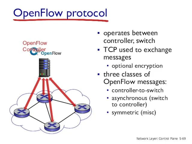
- 69. OpenFlow protocol operates between controller, switch TCP used to exchange messages optional encryption three classes of
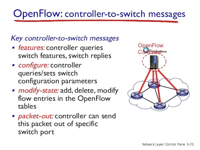
- 70. OpenFlow: controller-to-switch messages Key controller-to-switch messages features: controller queries switch features, switch replies configure: controller queries/sets
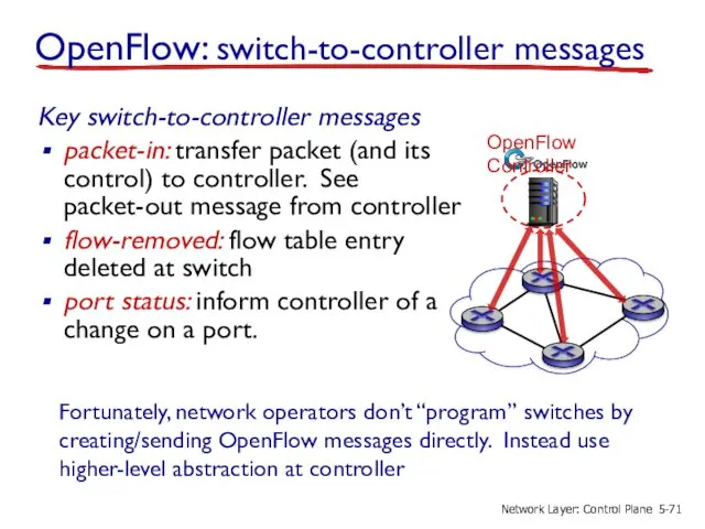
- 71. OpenFlow: switch-to-controller messages Key switch-to-controller messages packet-in: transfer packet (and its control) to controller. See packet-out
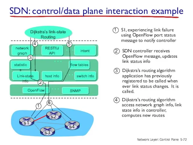
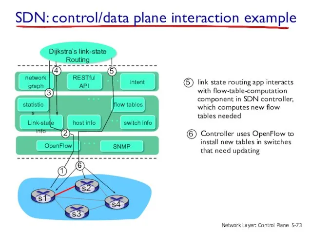
- 72. … … … … Dijkstra’s link-state Routing SDN: control/data plane interaction example 5- Network Layer: Control
- 73. … … … … Dijkstra’s link-state Routing SDN: control/data plane interaction example 5- Network Layer: Control
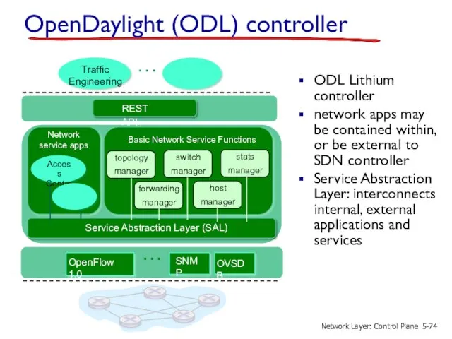
- 74. Basic Network Service Functions … Network service apps OpenDaylight (ODL) controller ODL Lithium controller network apps
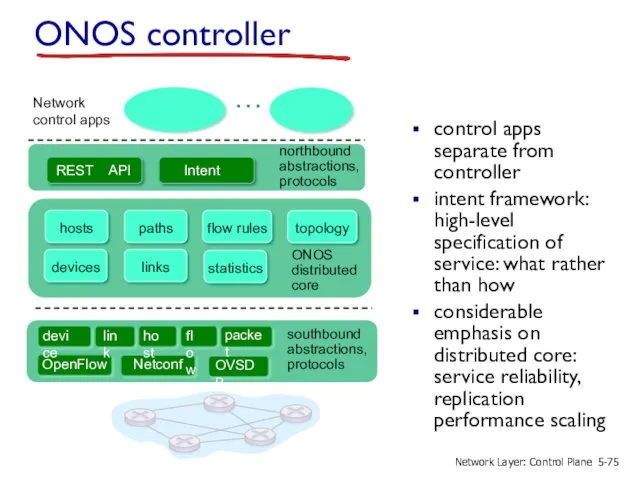
- 75. Network control apps … ONOS distributed core southbound abstractions, protocols northbound abstractions, protocols ONOS controller control
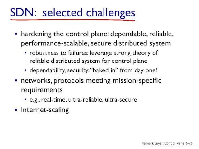
- 76. SDN: selected challenges hardening the control plane: dependable, reliable, performance-scalable, secure distributed system robustness to failures:
- 77. 5.1 introduction 5.2 routing protocols link state distance vector 5.3 intra-AS routing in the Internet: OSPF
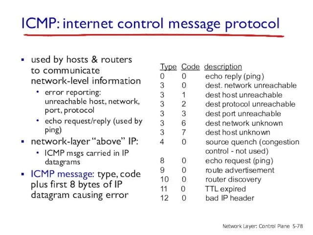
- 78. ICMP: internet control message protocol used by hosts & routers to communicate network-level information error reporting:
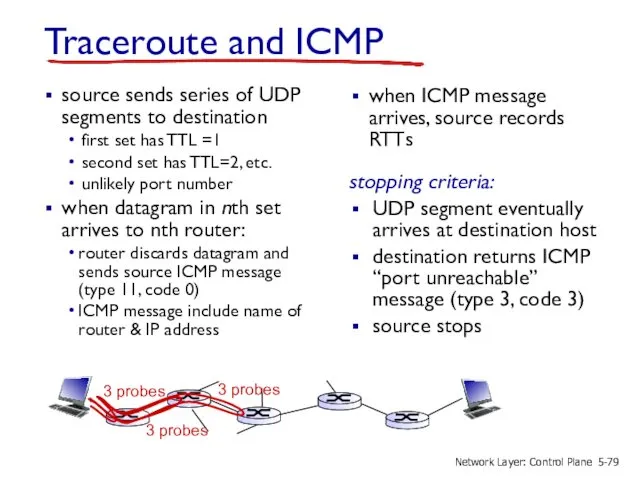
- 79. Traceroute and ICMP source sends series of UDP segments to destination first set has TTL =1
- 80. 5.1 introduction 5.2 routing protocols link state distance vector 5.3 intra-AS routing in the Internet: OSPF
- 81. What is network management? autonomous systems (aka “network”): 1000s of interacting hardware/software components other complex systems
- 82. Infrastructure for network management managed device managed device managed device managed device definitions: managed devices contain
- 83. SNMP protocol Two ways to convey MIB info, commands: managed device managed device request/response mode trap
- 84. SNMP protocol: message types GetRequest GetNextRequest GetBulkRequest manager-to-agent: “get me data” (data instance, next data in
- 85. SNMP protocol: message formats …. PDU type (0-3) Request ID Error Status (0-5) Error Index Name
- 87. Скачать презентацию
Chapter 5: network layer control plane
chapter goals: understand principles behind network
Chapter 5: network layer control plane
chapter goals: understand principles behind network
5.1 introduction
5.2 routing protocols
link state
distance vector
5.3 intra-AS routing in the Internet:
5.1 introduction
5.2 routing protocols
link state
distance vector
5.3 intra-AS routing in the Internet:
Network-layer functions
forwarding: move packets from router’s input to appropriate router output
data
Network-layer functions
forwarding: move packets from router’s input to appropriate router output
data
Per-router control plane
Individual routing algorithm components in each and every router
Per-router control plane
Individual routing algorithm components in each and every router
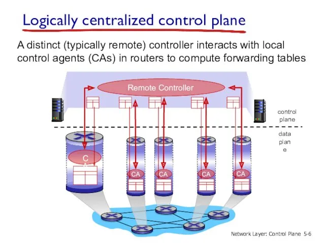
Logically centralized control plane
A distinct (typically remote) controller interacts with local
Logically centralized control plane
A distinct (typically remote) controller interacts with local

5.1 introduction
5.2 routing protocols
link state
distance vector
5.3 intra-AS routing in the Internet:
5.1 introduction
5.2 routing protocols
link state
distance vector
5.3 intra-AS routing in the Internet:
Routing protocols
Routing protocol goal: determine “good” paths (equivalently, routes), from sending
Routing protocols
Routing protocol goal: determine “good” paths (equivalently, routes), from sending
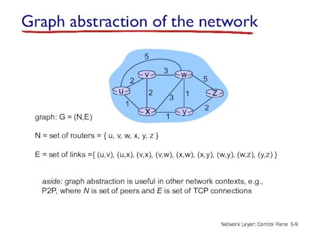
graph: G = (N,E)
N = set of routers = { u,
graph: G = (N,E)
N = set of routers = { u,
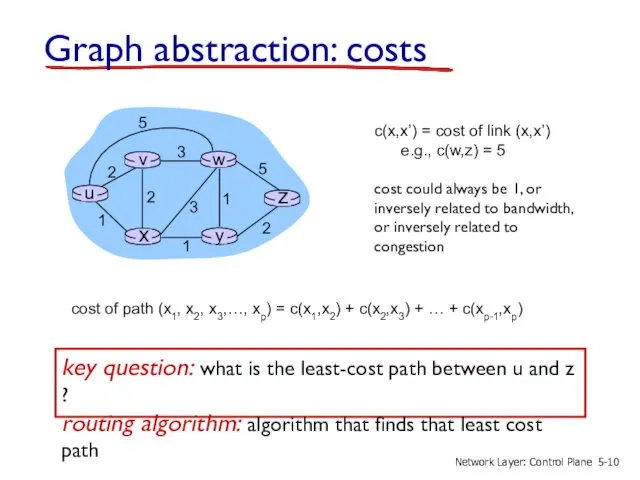
Graph abstraction: costs
c(x,x’) = cost of link (x,x’)
e.g., c(w,z) =
Graph abstraction: costs
c(x,x’) = cost of link (x,x’)
e.g., c(w,z) =
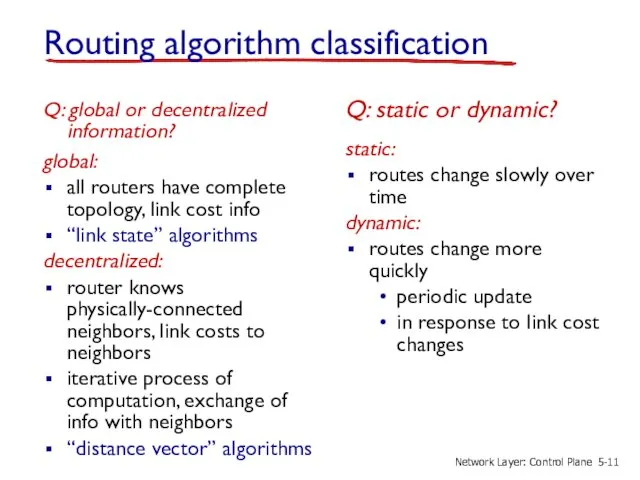
Routing algorithm classification
Q: global or decentralized information?
global:
all routers have complete topology,
Routing algorithm classification
Q: global or decentralized information?
global:
all routers have complete topology,

5.1 introduction
5.2 routing protocols
link state
distance vector
5.3 intra-AS routing in the Internet:
5.1 introduction
5.2 routing protocols
link state
distance vector
5.3 intra-AS routing in the Internet:
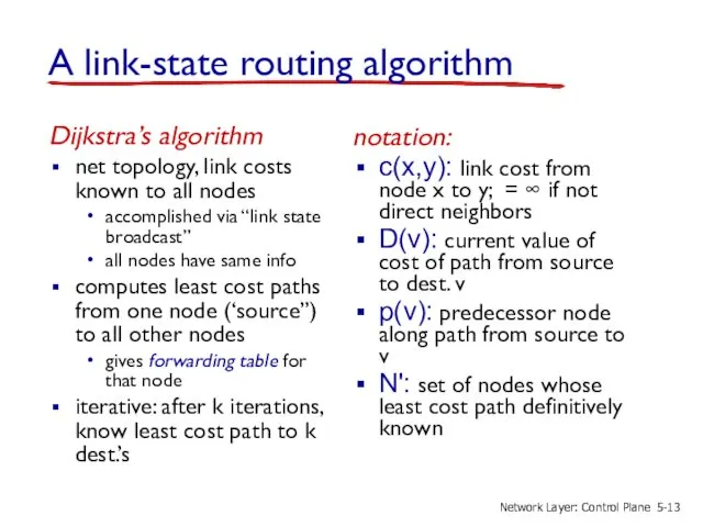
A link-state routing algorithm
Dijkstra’s algorithm
net topology, link costs known to all
A link-state routing algorithm
Dijkstra’s algorithm
net topology, link costs known to all
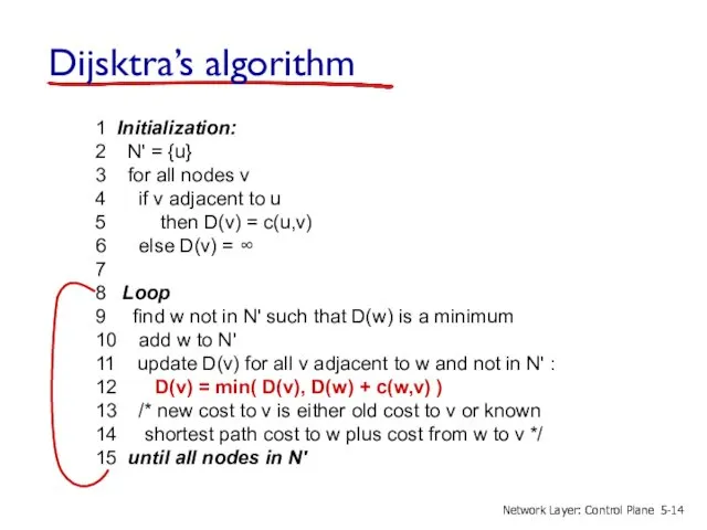
Dijsktra’s algorithm
1 Initialization:
2 N' = {u}
3 for all nodes
Dijsktra’s algorithm
1 Initialization:
2 N' = {u}
3 for all nodes
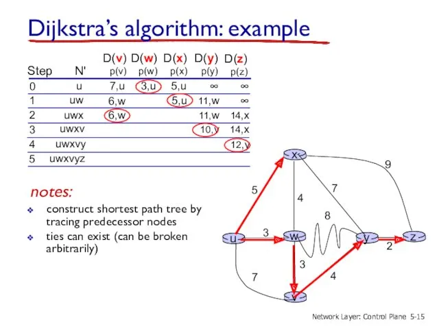
Dijkstra’s algorithm: example
Step
N'
D(v)
p(v)
0
1
2
3
4
5
D(w)
p(w)
D(x)
p(x)
D(y)
p(y)
D(z)
p(z)
u
uw
uwx
uwxv
uwxvy
12,y
notes:
construct shortest path tree by tracing predecessor nodes
ties
Dijkstra’s algorithm: example
Step
N'
D(v)
p(v)
0
1
2
3
4
5
D(w)
p(w)
D(x)
p(x)
D(y)
p(y)
D(z)
p(z)
u
uw
uwx
uwxv
uwxvy
12,y
notes:
construct shortest path tree by tracing predecessor nodes
ties
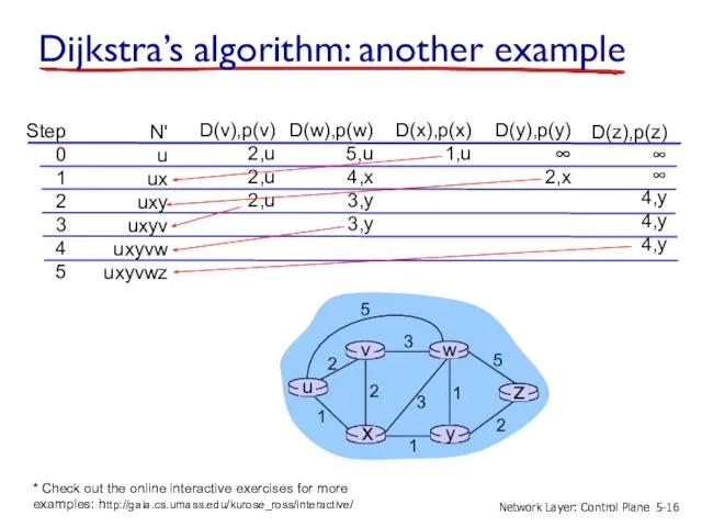
Dijkstra’s algorithm: another example
Step
0
1
2
3
4
5
N'
u
ux
uxy
uxyv
uxyvw
uxyvwz
D(v),p(v)
2,u
2,u
2,u
D(w),p(w)
5,u
4,x
3,y
3,y
D(x),p(x)
1,u
D(y),p(y)
∞
2,x
D(z),p(z)
∞
∞
4,y
4,y
4,y
5-
Network Layer: Control Plane
* Check out
Dijkstra’s algorithm: another example
Step
0
1
2
3
4
5
N'
u
ux
uxy
uxyv
uxyvw
uxyvwz
D(v),p(v)
2,u
2,u
2,u
D(w),p(w)
5,u
4,x
3,y
3,y
D(x),p(x)
1,u
D(y),p(y)
∞
2,x
D(z),p(z)
∞
∞
4,y
4,y
4,y
5-
Network Layer: Control Plane
* Check out
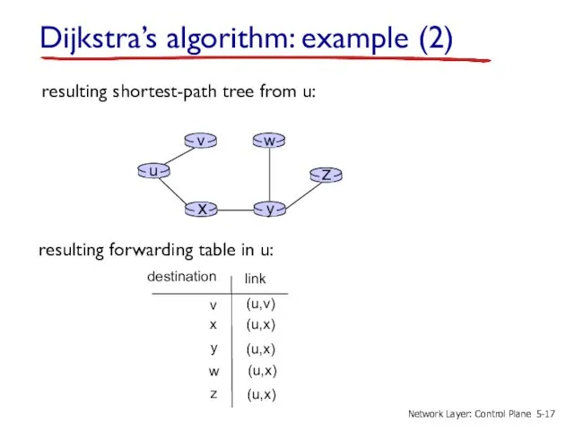
Dijkstra’s algorithm: example (2)
resulting shortest-path tree from u:
resulting forwarding table
Dijkstra’s algorithm: example (2)
resulting shortest-path tree from u:
resulting forwarding table
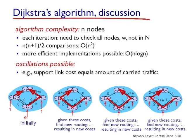
Dijkstra’s algorithm, discussion
algorithm complexity: n nodes
each iteration: need to check all
Dijkstra’s algorithm, discussion
algorithm complexity: n nodes
each iteration: need to check all
5.1 introduction
5.2 routing protocols
link state
distance vector
5.3 intra-AS routing in the Internet:
5.1 introduction
5.2 routing protocols
link state
distance vector
5.3 intra-AS routing in the Internet:
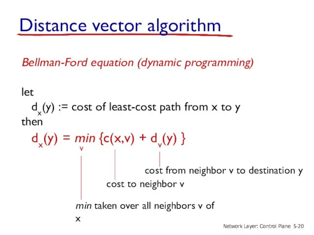
Distance vector algorithm
Bellman-Ford equation (dynamic programming)
let
dx(y) := cost of
Distance vector algorithm
Bellman-Ford equation (dynamic programming)
let
dx(y) := cost of
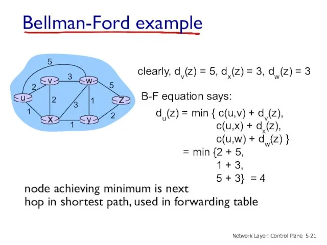
Bellman-Ford example
clearly, dv(z) = 5, dx(z) = 3, dw(z) =
Bellman-Ford example
clearly, dv(z) = 5, dx(z) = 3, dw(z) =
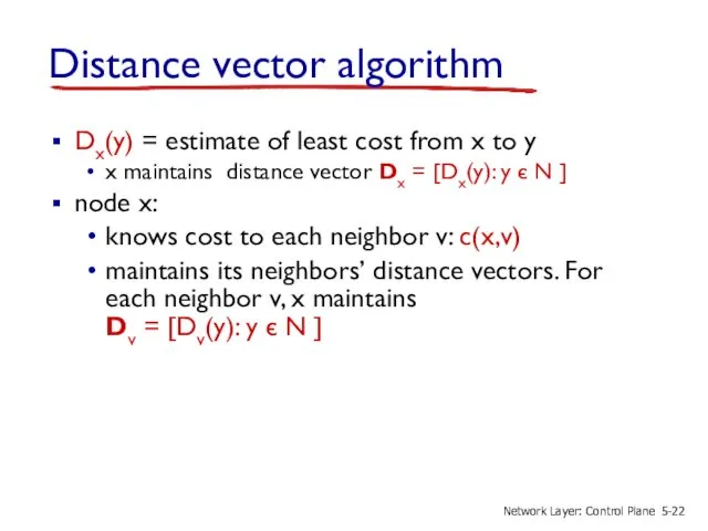
Distance vector algorithm
Dx(y) = estimate of least cost from x
Distance vector algorithm
Dx(y) = estimate of least cost from x
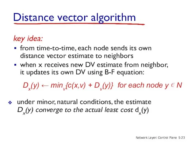
key idea:
from time-to-time, each node sends its own distance vector
key idea:
from time-to-time, each node sends its own distance vector
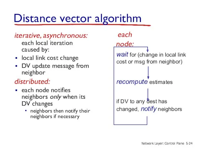
iterative, asynchronous: each local iteration caused by:
local link cost change
iterative, asynchronous: each local iteration caused by:
local link cost change
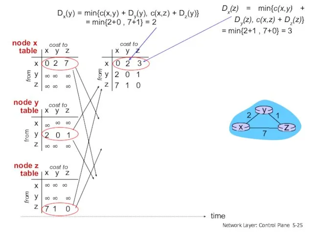
x y z
x
y
z
0 2 7
∞
∞
∞
∞
∞
∞
from
cost to
from
from
x y z
x
y
z
0
x y z
x
y
z
∞
∞
∞
∞
∞
cost to
x
x y z
x
y
z
0 2 7
∞
∞
∞
∞
∞
∞
from
cost to
from
from
x y z
x
y
z
0
x y z
x
y
z
∞
∞
∞
∞
∞
cost to
x
x y z
x
y
z
0 2 3
from
cost to
x y z
x
y
z
0 2 7
from
cost to
x
x y z
x
y
z
0 2 3
from
cost to
x y z
x
y
z
0 2 7
from
cost to
x
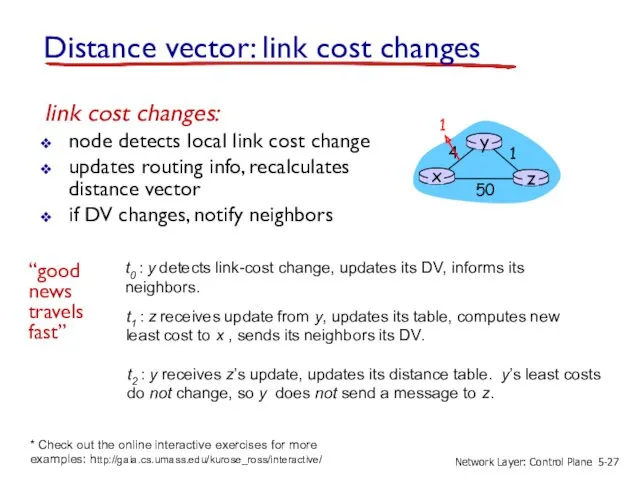
Distance vector: link cost changes
link cost changes:
node detects local link cost
Distance vector: link cost changes
link cost changes:
node detects local link cost
Distance vector: link cost changes
link cost changes:
node detects local link cost
Distance vector: link cost changes
link cost changes:
node detects local link cost
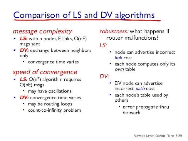
Comparison of LS and DV algorithms
message complexity
LS: with n nodes, E
Comparison of LS and DV algorithms
message complexity
LS: with n nodes, E
5.1 introduction
5.2 routing protocols
link state
distance vector
5.3 intra-AS routing in the Internet:
5.1 introduction
5.2 routing protocols
link state
distance vector
5.3 intra-AS routing in the Internet:
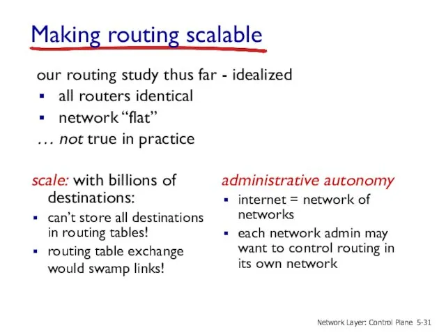
Making routing scalable
scale: with billions of destinations:
can’t store all destinations in
Making routing scalable
scale: with billions of destinations:
can’t store all destinations in
aggregate routers into regions known as “autonomous systems” (AS) (a.k.a. “domains”)
inter-AS
aggregate routers into regions known as “autonomous systems” (AS) (a.k.a. “domains”)
inter-AS
Interconnected ASes
forwarding table configured by both intra- and inter-AS routing algorithm
intra-AS
Interconnected ASes
forwarding table configured by both intra- and inter-AS routing algorithm
intra-AS
Inter-AS tasks
suppose router in AS1 receives datagram destined outside of AS1:
router
Inter-AS tasks
suppose router in AS1 receives datagram destined outside of AS1:
router
Intra-AS Routing
also known as interior gateway protocols (IGP)
most common intra-AS routing
Intra-AS Routing
also known as interior gateway protocols (IGP)
most common intra-AS routing
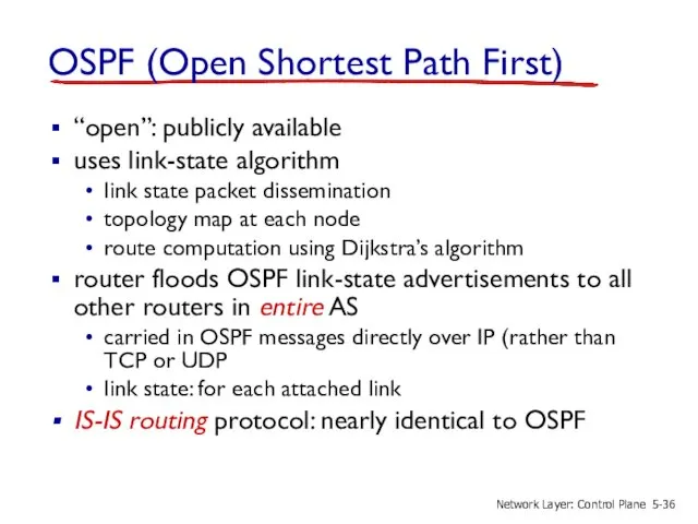
OSPF (Open Shortest Path First)
“open”: publicly available
uses link-state algorithm
link state
OSPF (Open Shortest Path First)
“open”: publicly available
uses link-state algorithm
link state
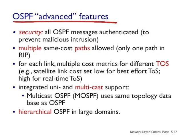
OSPF “advanced” features
security: all OSPF messages authenticated (to prevent malicious intrusion)
OSPF “advanced” features
security: all OSPF messages authenticated (to prevent malicious intrusion)
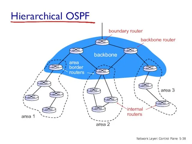
Hierarchical OSPF
boundary router
backbone router
area 1
area 2
area 3
backbone
area
border
routers
internal
routers
5-
Network Layer: Control Plane
Hierarchical OSPF
boundary router
backbone router
area 1
area 2
area 3
backbone
area
border
routers
internal
routers
5-
Network Layer: Control Plane
two-level hierarchy: local area, backbone.
link-state advertisements only in area
each nodes
two-level hierarchy: local area, backbone.
link-state advertisements only in area
each nodes
5.1 introduction
5.2 routing protocols
link state
distance vector
5.3 intra-AS routing in the Internet:
5.1 introduction
5.2 routing protocols
link state
distance vector
5.3 intra-AS routing in the Internet:
Internet inter-AS routing: BGP
BGP (Border Gateway Protocol): the de facto inter-domain
Internet inter-AS routing: BGP
BGP (Border Gateway Protocol): the de facto inter-domain
eBGP, iBGP connections
AS 2
AS 3
AS 1
5-
Network Layer: Control Plane
eBGP, iBGP connections
AS 2
AS 3
AS 1
5-
Network Layer: Control Plane
BGP basics
when AS3 gateway router 3a advertises path AS3,X to AS2
BGP basics
when AS3 gateway router 3a advertises path AS3,X to AS2
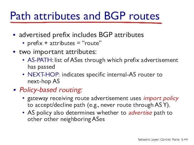
Path attributes and BGP routes
advertised prefix includes BGP attributes
prefix +
Path attributes and BGP routes
advertised prefix includes BGP attributes
prefix +
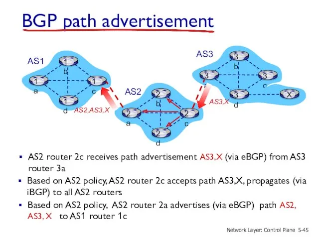
BGP path advertisement
Based on AS2 policy, AS2 router 2c accepts path
BGP path advertisement
Based on AS2 policy, AS2 router 2c accepts path
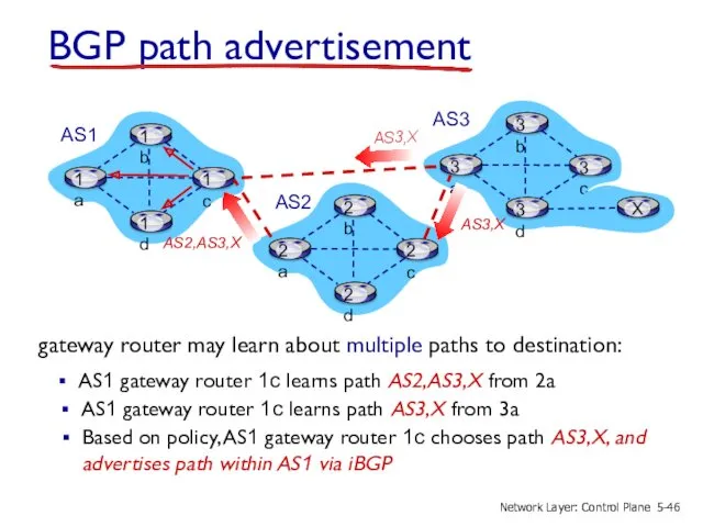
BGP path advertisement
AS1 gateway router 1c learns path AS2,AS3,X from 2a
AS2
AS3
AS1
gateway
BGP path advertisement
AS1 gateway router 1c learns path AS2,AS3,X from 2a
AS2
AS3
AS1
gateway
BGP messages
BGP messages exchanged between peers over TCP connection
BGP messages:
OPEN: opens
BGP messages
BGP messages exchanged between peers over TCP connection
BGP messages:
OPEN: opens
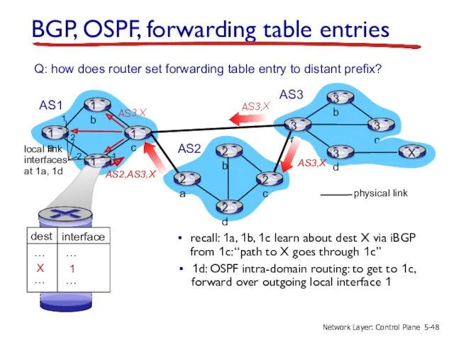
BGP, OSPF, forwarding table entries
recall: 1a, 1b, 1c learn about dest
BGP, OSPF, forwarding table entries
recall: 1a, 1b, 1c learn about dest
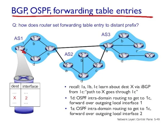
BGP, OSPF, forwarding table entries
recall: 1a, 1b, 1c learn about dest
BGP, OSPF, forwarding table entries
recall: 1a, 1b, 1c learn about dest
BGP route selection
router may learn about more than one route to
BGP route selection
router may learn about more than one route to
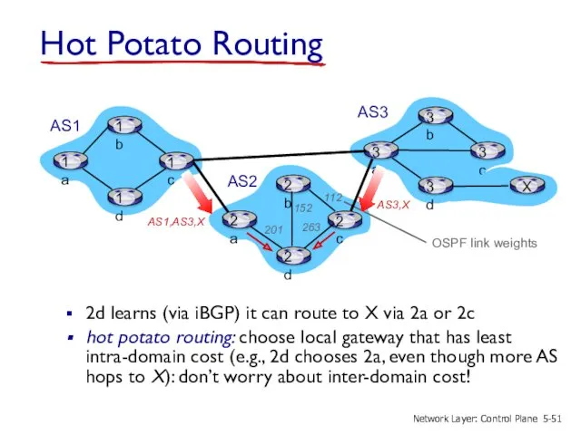
Hot Potato Routing
2d learns (via iBGP) it can route to X
Hot Potato Routing
2d learns (via iBGP) it can route to X
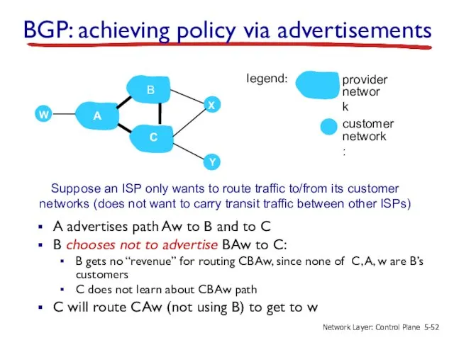
A advertises path Aw to B and to C
B chooses not
A advertises path Aw to B and to C
B chooses not
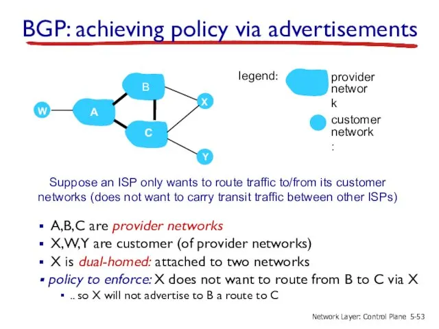
BGP: achieving policy via advertisements
A,B,C are provider networks
X,W,Y are customer (of
BGP: achieving policy via advertisements
A,B,C are provider networks
X,W,Y are customer (of
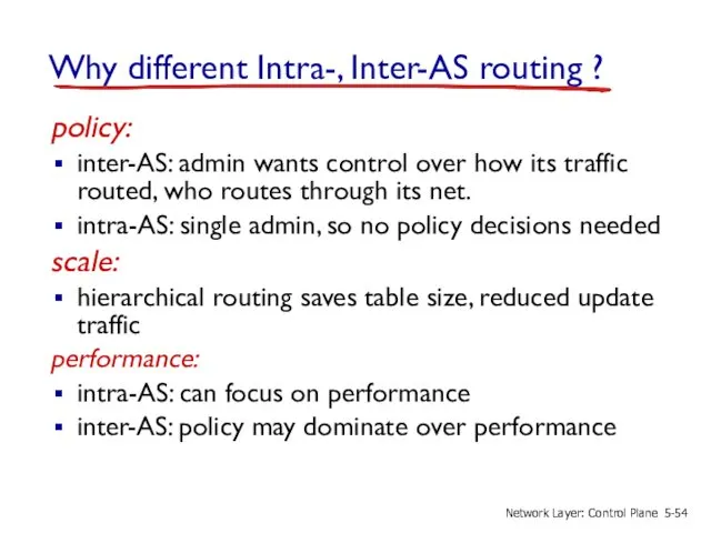
Why different Intra-, Inter-AS routing ?
policy:
inter-AS: admin wants control
Why different Intra-, Inter-AS routing ?
policy:
inter-AS: admin wants control
5.1 introduction
5.2 routing protocols
link state
distance vector
5.3 intra-AS routing in the Internet:
5.1 introduction
5.2 routing protocols
link state
distance vector
5.3 intra-AS routing in the Internet:
Software defined networking (SDN)
Internet network layer: historically has been implemented via
Software defined networking (SDN)
Internet network layer: historically has been implemented via
Recall: per-router control plane
Individual routing algorithm components in each and every
Recall: per-router control plane
Individual routing algorithm components in each and every
Recall: logically centralized control plane
A distinct (typically remote) controller interacts with
Recall: logically centralized control plane
A distinct (typically remote) controller interacts with
Software defined networking (SDN)
Why a logically centralized control plane?
easier network management:
Software defined networking (SDN)
Why a logically centralized control plane?
easier network management:
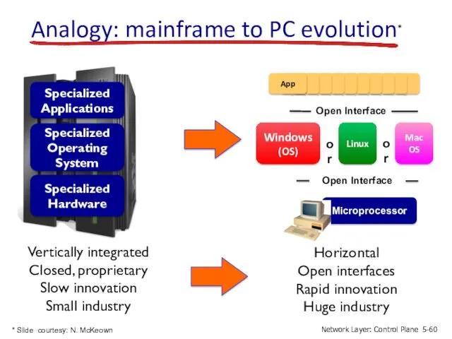
Vertically integrated
Closed, proprietary
Slow innovation
Small industry
Specialized
Operating
System
Specialized
Hardware
Specialized
Applications
Horizontal
Open interfaces
Rapid innovation
Huge industry
Analogy: mainframe to PC
Vertically integrated
Closed, proprietary
Slow innovation
Small industry
Specialized
Operating
System
Specialized
Hardware
Specialized
Applications
Horizontal
Open interfaces
Rapid innovation
Huge industry
Analogy: mainframe to PC
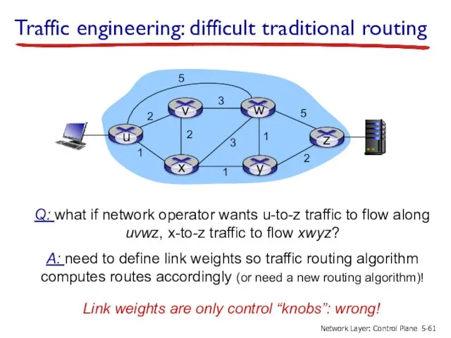
Traffic engineering: difficult traditional routing
Q: what if network operator wants u-to-z
Traffic engineering: difficult traditional routing
Q: what if network operator wants u-to-z
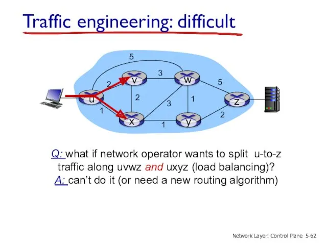
Traffic engineering: difficult
Q: what if network operator wants to split u-to-z
Traffic engineering: difficult
Q: what if network operator wants to split u-to-z
2
2
1
3
1
1
2
5
3
5
Traffic engineering: difficult
Q: what if w wants to route blue and
2
2
1
3
1
1
2
5
3
5
Traffic engineering: difficult
Q: what if w wants to route blue and
Software defined networking (SDN)
3. control plane functions external to data-plane switches
…
routing
access
Software defined networking (SDN)
3. control plane functions external to data-plane switches
…
routing
access
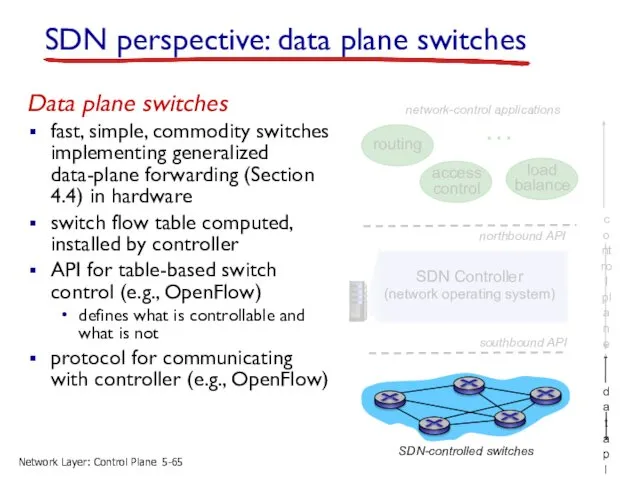
SDN perspective: data plane switches
Data plane switches
fast, simple, commodity switches implementing
SDN perspective: data plane switches
Data plane switches
fast, simple, commodity switches implementing
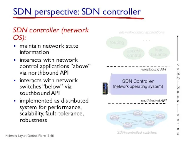
SDN perspective: SDN controller
SDN controller (network OS):
maintain network state information
interacts
SDN perspective: SDN controller
SDN controller (network OS):
maintain network state information
interacts
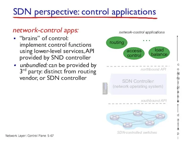
SDN perspective: control applications
network-control apps:
“brains” of control: implement control functions using
SDN perspective: control applications
network-control apps:
“brains” of control: implement control functions using
Network-wide distributed, robust state management
Communication to/from controlled devices
…
…
…
…
Network-wide distributed, robust state management
Communication to/from controlled devices
…
…
…
…
OpenFlow protocol
operates between controller, switch
TCP used to exchange messages
optional encryption
three classes
OpenFlow protocol
operates between controller, switch
TCP used to exchange messages
optional encryption
three classes
OpenFlow: controller-to-switch messages
Key controller-to-switch messages
features: controller queries switch features, switch replies
configure:
OpenFlow: controller-to-switch messages
Key controller-to-switch messages
features: controller queries switch features, switch replies
configure:
OpenFlow: switch-to-controller messages
Key switch-to-controller messages
packet-in: transfer packet (and its control) to
OpenFlow: switch-to-controller messages
Key switch-to-controller messages
packet-in: transfer packet (and its control) to
…
…
…
…
Dijkstra’s link-state
Routing
SDN: control/data plane interaction example
5-
Network
…
…
…
…
Dijkstra’s link-state
Routing
SDN: control/data plane interaction example
5-
Network
…
…
…
…
Dijkstra’s link-state
Routing
SDN: control/data plane interaction example
5-
Network
…
…
…
…
Dijkstra’s link-state
Routing
SDN: control/data plane interaction example
5-
Network
Basic Network Service Functions
…
Network service apps
OpenDaylight (ODL) controller
ODL Lithium controller
network
Basic Network Service Functions
…
Network service apps
OpenDaylight (ODL) controller
ODL Lithium controller
network
Network
control apps
…
ONOS
distributed core
southbound abstractions,
protocols
northbound abstractions,
protocols
ONOS controller
control apps separate
Network
control apps
…
ONOS
distributed core
southbound abstractions,
protocols
northbound abstractions,
protocols
ONOS controller
control apps separate
SDN: selected challenges
hardening the control plane: dependable, reliable, performance-scalable, secure distributed
SDN: selected challenges
hardening the control plane: dependable, reliable, performance-scalable, secure distributed
5.1 introduction
5.2 routing protocols
link state
distance vector
5.3 intra-AS routing in the Internet:
5.1 introduction
5.2 routing protocols
link state
distance vector
5.3 intra-AS routing in the Internet:
ICMP: internet control message protocol
used by hosts & routers to communicate
ICMP: internet control message protocol
used by hosts & routers to communicate
Traceroute and ICMP
source sends series of UDP segments to destination
first set
Traceroute and ICMP
source sends series of UDP segments to destination
first set
5.1 introduction
5.2 routing protocols
link state
distance vector
5.3 intra-AS routing in the Internet:
5.1 introduction
5.2 routing protocols
link state
distance vector
5.3 intra-AS routing in the Internet:
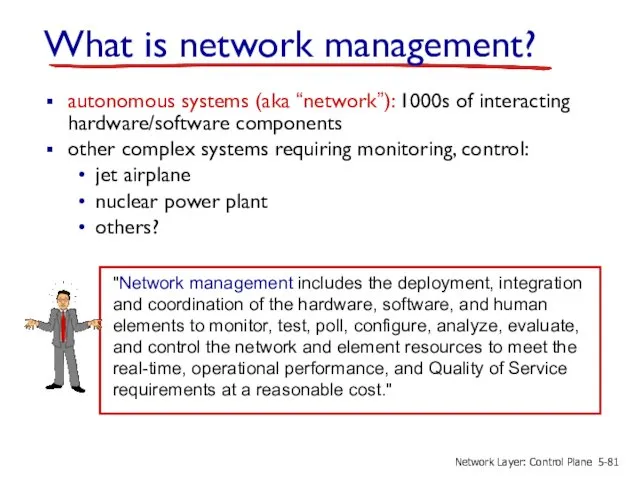
What is network management?
autonomous systems (aka “network”): 1000s of interacting hardware/software
What is network management?
autonomous systems (aka “network”): 1000s of interacting hardware/software
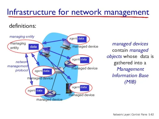
Infrastructure for network management
managed device
managed device
managed device
managed device
definitions:
managed devices contain managed
Infrastructure for network management
managed device
managed device
managed device
managed device
definitions:
managed devices contain managed
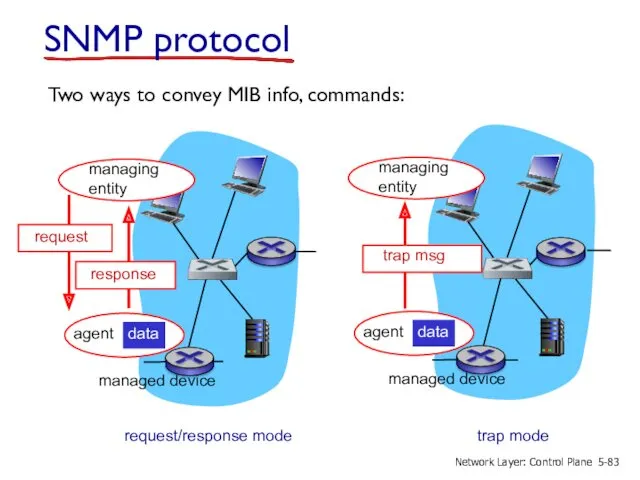
SNMP protocol
Two ways to convey MIB info, commands:
managed device
managed device
request/response mode
trap
SNMP protocol
Two ways to convey MIB info, commands:
managed device
managed device
request/response mode
trap
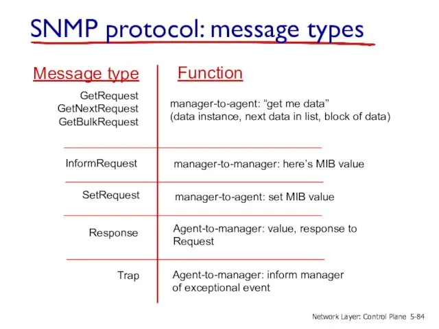
SNMP protocol: message types
GetRequest
GetNextRequest
GetBulkRequest
manager-to-agent: “get me data”
(data instance, next data in
SNMP protocol: message types
GetRequest
GetNextRequest
GetBulkRequest
manager-to-agent: “get me data”
(data instance, next data in
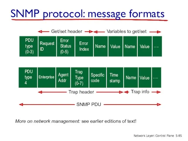
SNMP protocol: message formats
….
PDU
type
(0-3)
Request
ID
Error
Status
(0-5)
Error
Index
Name
Value
Name
Value
….
PDU
type
4
Enterprise
Agent
Addr
Trap
Type
(0-7)
Specific
code
Time
stamp
Name
Value
Get/set header
Variables to get/set
Trap header
Trap info
SNMP PDU
5-
Network Layer:
SNMP protocol: message formats
….
PDU
type
(0-3)
Request
ID
Error
Status
(0-5)
Error
Index
Name
Value
Name
Value
….
PDU
type
4
Enterprise
Agent
Addr
Trap
Type
(0-7)
Specific
code
Time
stamp
Name
Value
Get/set header
Variables to get/set
Trap header
Trap info
SNMP PDU
5-
Network Layer:
 Основы облачных вычислений
 Пиши код правильно
 Параллельное и распределенное программирование. Технология программирования гетерогенных систем
 Языки программирования. Язык Паскаль
 Операції над об’єктами файлової системи
 Формирование списков на Web-странице
 Государственная информационная система жилищно-коммунального хозяйства
 Правовые нормы, относящиеся к информации, правонарушения в информационной сфере, меры их предупреждения
 Приложение TapTable
 Техника безопасности в кабинете информатики
 Загальні відомості про електронну комерцію
 Принципы работы в сети интернет
 Пространственная фильтрация, обработка в частотной области и восстановление изображения (Matlab)
 Безопасный интернет
 Основи растрової графіки. Використання фото та кліпартів. Растрова анімація
 Операционные системы
 Кодирование и обработка звуковой информации
 Әлеуметтік желілердегі хаттар тілі:түрі,лексика-грамматикалық сипаты
 Создание простейшей веб-страницы. Работа в редакторе Блокнот
 Optical identification using imperfections in 2D materials
 Носители информации
 Компьютерные вирусы и антивирусные программы
 Как устроена книга
 Логика. Основные понятия
 Операционные системы
 Системы перевода и распознавания текстов
 Operators & Expressions. Lecture 3
 Подготовка к СОР. 9 класс