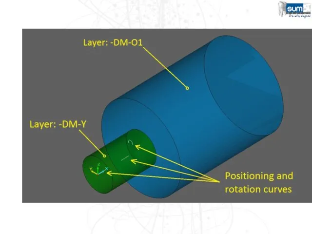
- Premilled guide

Содержание
- 2. Pre-Milled Workflow New Job (Fixture is automatically Imported) Fixture must have the CYLINDER_POSITION curve. Import .STL
- 3. Pre-Milled Setup Pre-Requisites Fixture File Must be properly orientated with the machine’s axes. Blank Files One
- 4. Creating your Equipment & Blanks It is usually ideal to prepare your Equipment and Pre-Milled Blank
- 5. Equipment Creation (.EQP Files) Pre-Milled Blank Creation (.BLK Files) Discussion Points
- 6. EQUIPMENT (.EQP)
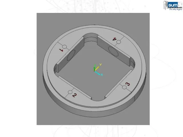
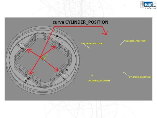
- 7. The equipment defines: The number of pre-milled cylinders that can be mounted on the fixture at
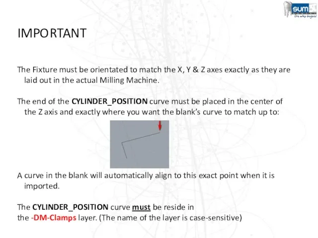
- 10. IMPORTANT The Fixture must be orientated to match the X, Y & Z axes exactly as
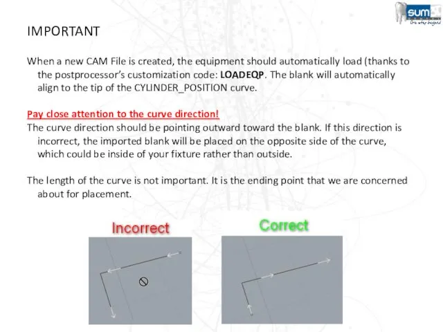
- 11. IMPORTANT When a new CAM File is created, the equipment should automatically load (thanks to the
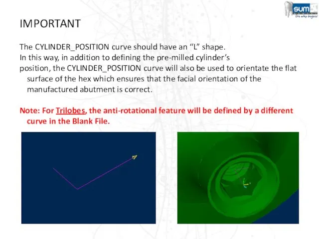
- 12. IMPORTANT The CYLINDER_POSITION curve should have an “L” shape. In this way, in addition to defining
- 13. CYLINDER_POSITION curve “L” shape sample
- 14. Converting your prepared file into an Equipment File (.EQP) Before SUM3D can use your prepared equipment
- 15. Open SUM3D (Maximum Level UI) Go to File > New on the File Menu Navigate to
- 16. You should now see a blank CAM file. Click on File > Import on the File
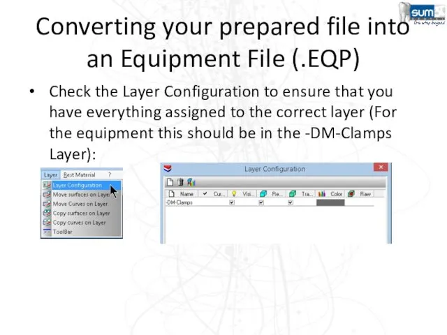
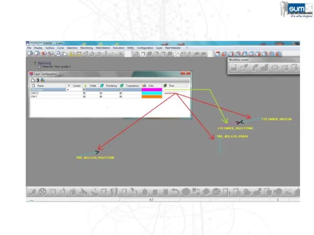
- 17. Converting your prepared file into an Equipment File (.EQP) Check the Layer Configuration to ensure that
- 18. Converting your prepared file into an Equipment File (.EQP) Click on Curve > Change Name to
- 19. Converting your prepared file into an Equipment File (.EQP) Click on Curve > Reverse Curve to
- 20. Converting your prepared file into an Equipment File (.EQP) If the Curves and the Layers are
- 21. Pre-Milled Blanks(.BLK)
- 22. Pre-Milled Blank Files (.BLK) The .BLK file must meet the following requirements: The Pre-Milled Blank Surface
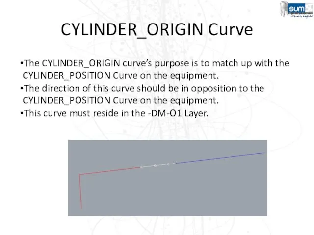
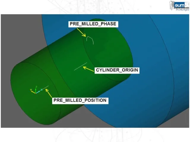
- 23. CYLINDER_ORIGIN Curve The CYLINDER_ORIGIN curve’s purpose is to match up with the CYLINDER_POSITION Curve on the
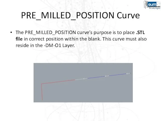
- 24. PRE_MILLED_POSITION Curve The PRE_MILLED_POSITION curve’s purpose is to place .STL file in correct position within the
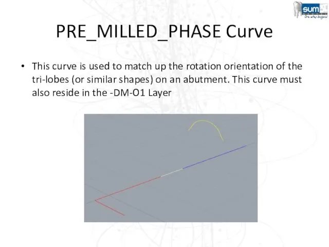
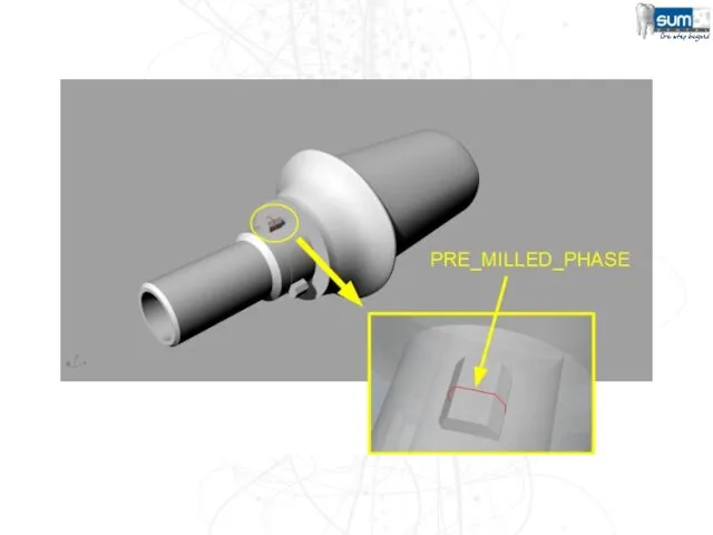
- 25. PRE_MILLED_PHASE Curve This curve is used to match up the rotation orientation of the tri-lobes (or
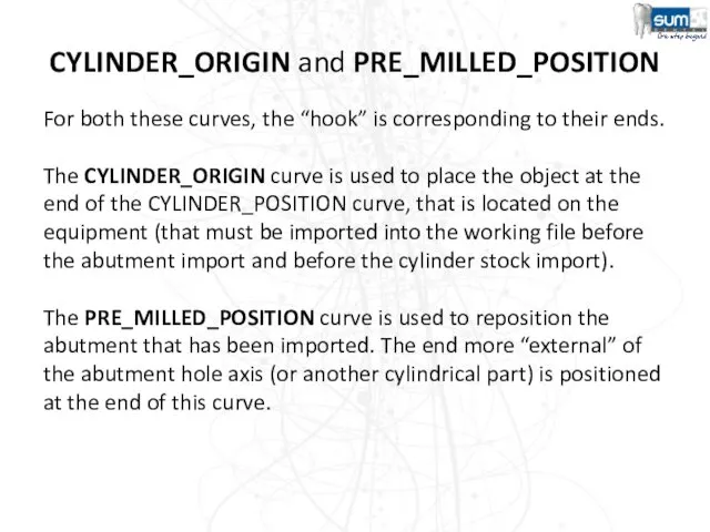
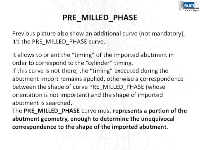
- 30. CYLINDER_ORIGIN and PRE_MILLED_POSITION For both these curves, the “hook” is corresponding to their ends. The CYLINDER_ORIGIN
- 31. PRE_MILLED_PHASE Previous picture also show an additional curve (not mandatory), it’s the PRE_MILLED_PHASE curve. It allows
- 32. IMPORTANT The PRE_MILLED_PHASE curve must be positioned in same area in which the corresponding part to
- 33. Enhancement 2015 In order to allow to correctly position the "pre-milled abutments" even when it is
- 34. Enhancement 2015 In the creation of the BLK files (cylindric blanks) for the pre-milled abutments, it's
- 35. Machining Strategy (Extend Fence To Cylinder) Option for 4 axis continuously 360 degree (like a lathe)
- 36. Machining Strategy ang1 tool axis rotation angle related to the machining angle. Normally it’s zero ang2
- 37. Machining Strategy ROUGHING 4 AXES ZI… Z Increment with the increment value between passes
- 38. Machining Strategy This machining operation allow to mill in 3 axis or in 4 axis .
- 39. Machining Strategy Spiral only Option for the 4 axis machining (lathe)
- 40. Machining Strategy This machining operation allow to handle the finishes of some areas such as the
- 41. Machining Strategy Ex. 1:
- 42. Machining Strategy Ex. 2:
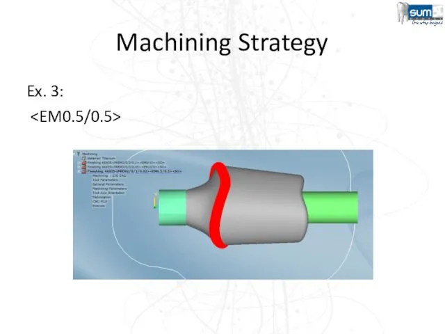
- 43. Machining Strategy Ex. 3:
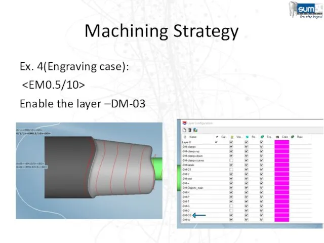
- 44. Machining Strategy Ex. 4(Engraving case): Enable the layer –DM-03
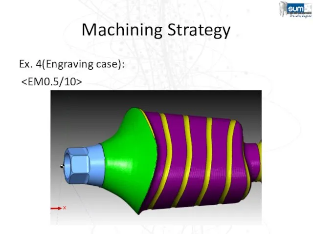
- 45. Machining Strategy Ex. 4(Engraving case):
- 47. Скачать презентацию
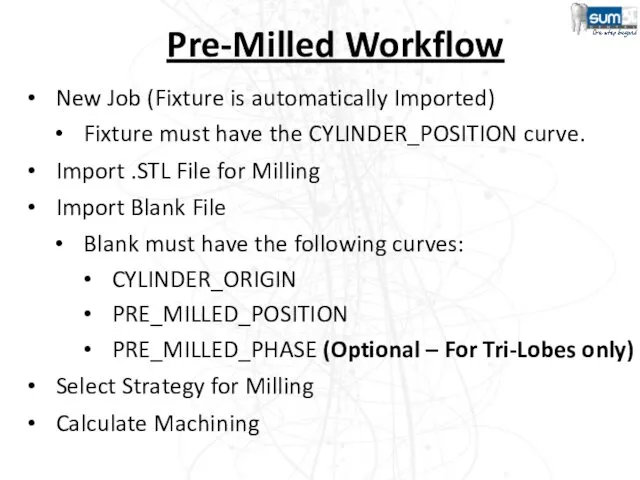
Pre-Milled Workflow
New Job (Fixture is automatically Imported)
Fixture must have the CYLINDER_POSITION
Pre-Milled Workflow
New Job (Fixture is automatically Imported)
Fixture must have the CYLINDER_POSITION
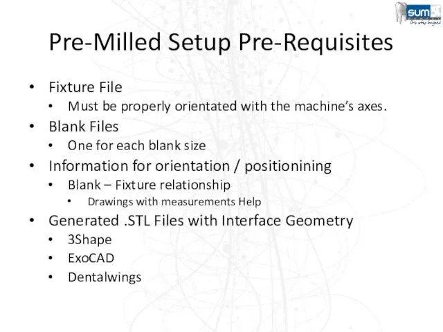
Pre-Milled Setup Pre-Requisites
Fixture File
Must be properly orientated with the machine’s
Pre-Milled Setup Pre-Requisites
Fixture File
Must be properly orientated with the machine’s
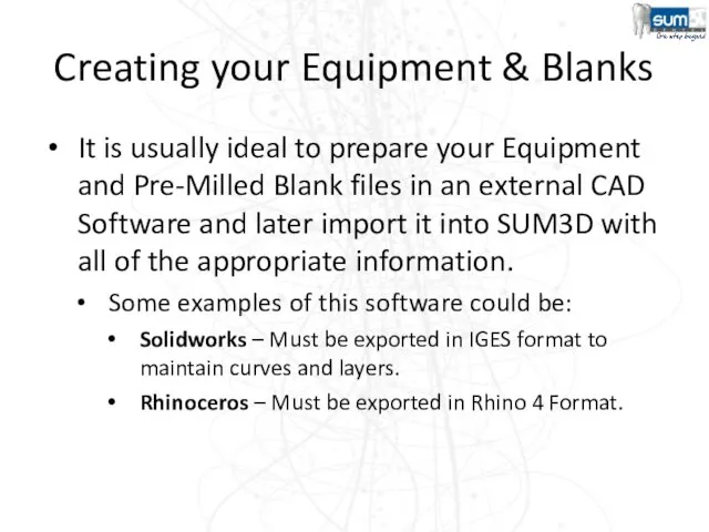
Creating your Equipment & Blanks
It is usually ideal to prepare your
Creating your Equipment & Blanks
It is usually ideal to prepare your
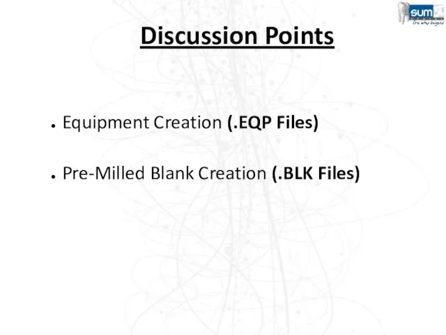
Equipment Creation (.EQP Files)
Pre-Milled Blank Creation (.BLK Files)
Discussion Points
Equipment Creation (.EQP Files)
Pre-Milled Blank Creation (.BLK Files)
Discussion Points
EQUIPMENT (.EQP)
EQUIPMENT (.EQP)
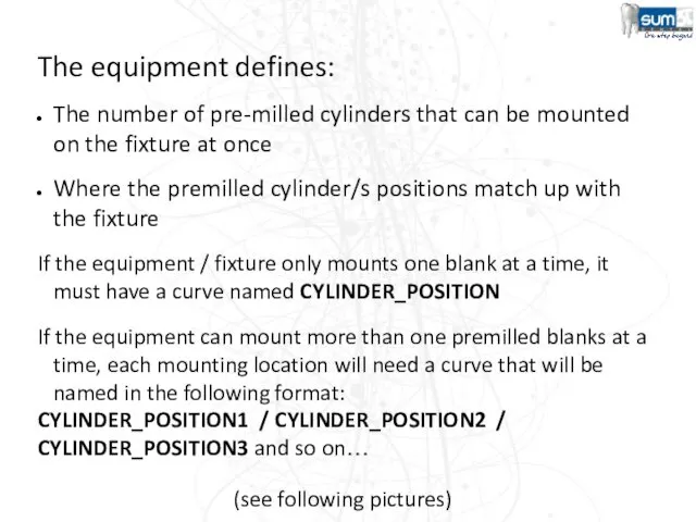
The equipment defines:
The number of pre-milled cylinders that can be mounted
The equipment defines:
The number of pre-milled cylinders that can be mounted
IMPORTANT
The Fixture must be orientated to match the X, Y &
IMPORTANT
The Fixture must be orientated to match the X, Y &
IMPORTANT
When a new CAM File is created, the equipment should automatically
IMPORTANT
When a new CAM File is created, the equipment should automatically
IMPORTANT
The CYLINDER_POSITION curve should have an “L” shape.
In this way,
IMPORTANT
The CYLINDER_POSITION curve should have an “L” shape.
In this way,
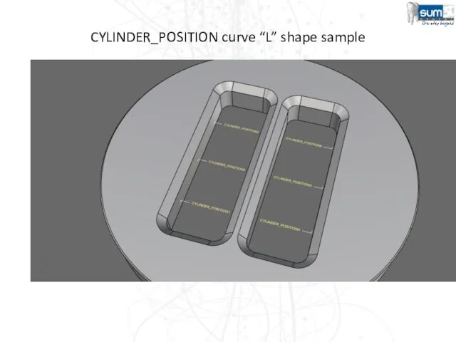
CYLINDER_POSITION curve “L” shape sample
CYLINDER_POSITION curve “L” shape sample
Converting your prepared file into an Equipment File (.EQP)
Before SUM3D can
Converting your prepared file into an Equipment File (.EQP)
Before SUM3D can
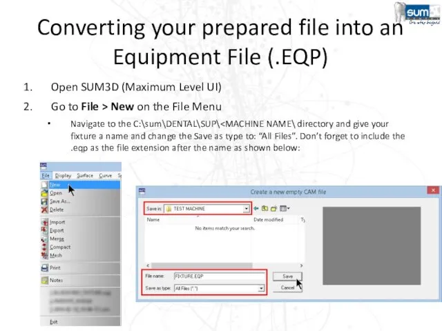
Open SUM3D (Maximum Level UI)
Go to File > New on the
Open SUM3D (Maximum Level UI)
Go to File > New on the
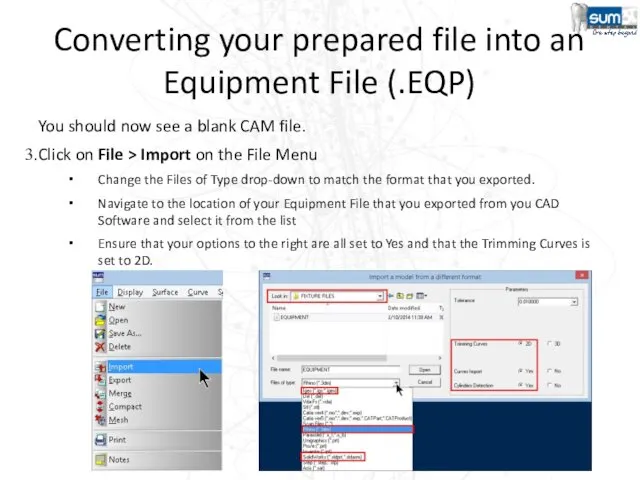
You should now see a blank CAM file.
Click on File >
You should now see a blank CAM file.
Click on File >
Converting your prepared file into an Equipment File (.EQP)
Check the Layer
Converting your prepared file into an Equipment File (.EQP)
Check the Layer
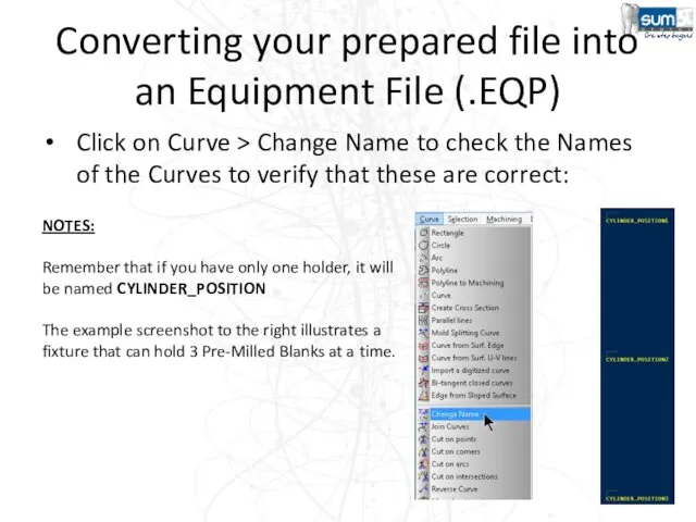
Converting your prepared file into an Equipment File (.EQP)
Click on Curve
Converting your prepared file into an Equipment File (.EQP)
Click on Curve
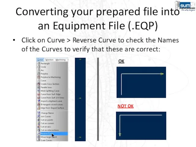
Converting your prepared file into an Equipment File (.EQP)
Click on Curve
Converting your prepared file into an Equipment File (.EQP)
Click on Curve
Converting your prepared file into an Equipment File (.EQP)
If the Curves
Converting your prepared file into an Equipment File (.EQP)
If the Curves

Pre-Milled Blanks(.BLK)
Pre-Milled Blanks(.BLK)
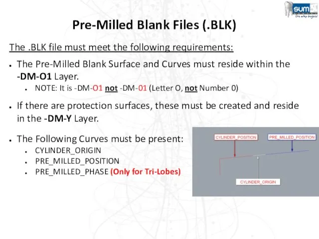
Pre-Milled Blank Files (.BLK)
The .BLK file must meet the following requirements:
The
Pre-Milled Blank Files (.BLK)
The .BLK file must meet the following requirements:
The
CYLINDER_ORIGIN Curve
The CYLINDER_ORIGIN curve’s purpose is to match up with the
CYLINDER_ORIGIN Curve
The CYLINDER_ORIGIN curve’s purpose is to match up with the
PRE_MILLED_POSITION Curve
The PRE_MILLED_POSITION curve’s purpose is to place .STL file in
PRE_MILLED_POSITION Curve
The PRE_MILLED_POSITION curve’s purpose is to place .STL file in
PRE_MILLED_PHASE Curve
This curve is used to match up the rotation orientation
PRE_MILLED_PHASE Curve
This curve is used to match up the rotation orientation
CYLINDER_ORIGIN and PRE_MILLED_POSITION
For both these curves, the “hook” is corresponding
CYLINDER_ORIGIN and PRE_MILLED_POSITION
For both these curves, the “hook” is corresponding
PRE_MILLED_PHASE
Previous picture also show an additional curve (not mandatory), it’s the
PRE_MILLED_PHASE
Previous picture also show an additional curve (not mandatory), it’s the
IMPORTANT
The PRE_MILLED_PHASE curve must be positioned in same area
in which
IMPORTANT
The PRE_MILLED_PHASE curve must be positioned in same area
in which
Enhancement 2015
In order to allow to correctly position the "pre-milled abutments"
Enhancement 2015
In order to allow to correctly position the "pre-milled abutments"
Enhancement 2015
In the creation of the BLK files (cylindric blanks) for
Enhancement 2015
In the creation of the BLK files (cylindric blanks) for
Machining Strategy
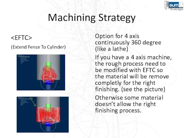
(Extend Fence To Cylinder)
Option for 4 axis continuously 360 degree
Machining Strategy
Option for 4 axis continuously 360 degree
(Extend Fence To Cylinder)
Machining Strategy
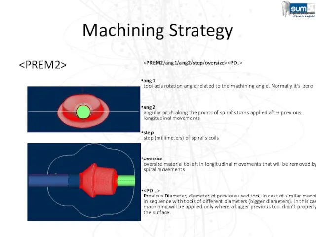
ang1
tool axis rotation angle related to the machining angle. Normally
Machining Strategy
ang1
tool axis rotation angle related to the machining angle. Normally
Machining Strategy
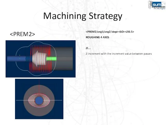
ROUGHING 4 AXES
ZI…
Z Increment with the increment value between passes
Machining Strategy
ROUGHING 4 AXES
ZI…
Z Increment with the increment value between passes
Machining Strategy
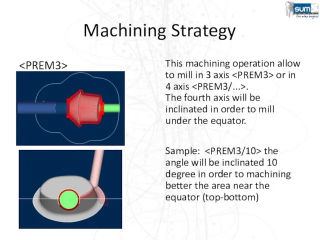
This machining operation allow to mill in 3 axis
Machining Strategy
This machining operation allow to mill in 3 axis
Machining Strategy
Spiral only
Option for the 4 axis machining (lathe)
Machining Strategy
Option for the 4 axis machining (lathe)
Spiral only
Machining Strategy
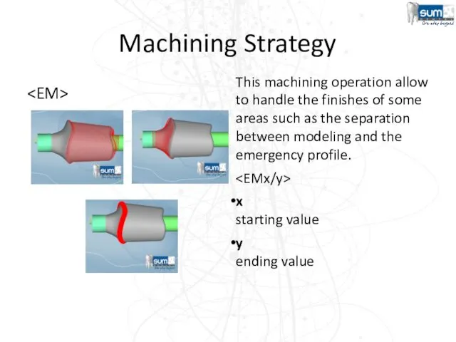
This machining operation allow to handle the finishes of some
Machining Strategy
This machining operation allow to handle the finishes of some
Machining Strategy
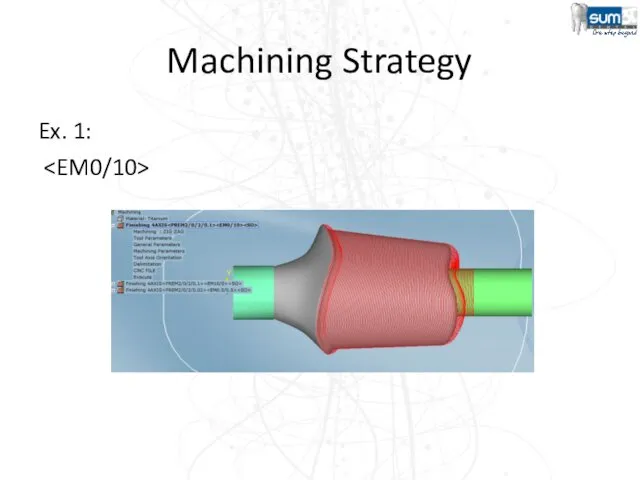
Ex. 1:
Machining Strategy
Ex. 1:
Machining Strategy
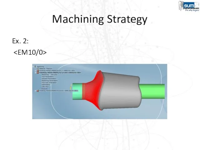
Ex. 2:
Machining Strategy
Ex. 2:
Machining Strategy
Ex. 3:
Machining Strategy
Ex. 3:
Machining Strategy
Ex. 4(Engraving case):
Enable the layer –DM-03
Machining Strategy
Ex. 4(Engraving case):
Enable the layer –DM-03
Machining Strategy
Ex. 4(Engraving case):
Machining Strategy
Ex. 4(Engraving case):
 Программные средства реализации информационных процессов
 Основы программирования. ФИСТ 1 курс. Двухмерные массивы. FOR. BREAK. Работа с файлами. Лекция 10
 Операционная система
 Личный кабинет клиента my.ponyexpress.ru
 Радио России
 Принципы обработки информации компьютером. Алгоритмы и способы их описания
 Модели информационных процессов
 Эффективный поиск в интернете. Сайты спортивных федераций РФ
 Методы сбора и обработки данных при помощи Python
 WebGL. Основные положения
 Способы шифрования
 Симплекс-метод для решения задач линейного программирования
 Самообразование – одна из форм повышения профессионального мастерства педагога
 Информатика и ИКТ. Введение
 Алгоритм создания основных объектов в Mirosoft Office Access 2007
 Язык программирования Бейсик. Обучающая программа по изучению языка
 Сети связи следующего поколения (NGN)
 DOM-LAND. Объединяем людей
 Оформление декларацию 3-НДФЛ через Личный кабинет налогоплательщика
 Конструктор рабочих программ
 Сумісність і множинні прикладні середовища. Способи реалізації прикладних програмних середовищ. Технології віртуалізації
 Види комп'ютерної графіки
 Мультимедиа в журналистике. А нужно ли? И как?
 Состав и назначение интегрированных САПР. Лекция 5
 Информационные ресурсы интернета
 Мониторинг деятельности библиотек по продвижению чтения в социальных сетях
 Введение в IT
 ЕГЭ информатика, задания А1 и А2