- Surface geometry for CAD

Содержание
- 2. SURFACE GEOMETRY Bezier, basic B-spline and NURBS can all be used to create surfaces. When surfaces
- 3. SURFACE GEOMETRY Perhaps the simplest surface, from a construction point of view, is a curve extruded
- 4. SURFACE GEOMETRY Extending this approach we can create surfaces by moving curves along other curves. Common
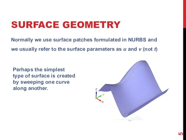
- 5. SURFACE GEOMETRY Normally we use surface patches formulated in NURBS and we usually refer to the
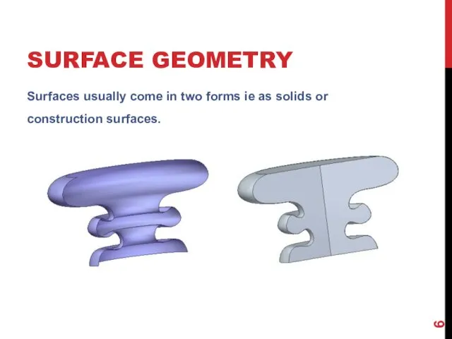
- 6. SURFACE GEOMETRY Surfaces usually come in two forms ie as solids or construction surfaces.
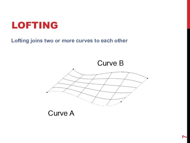
- 7. LOFTING Lofting joins two or more curves to each other Curve A Curve B Curve A
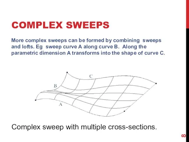
- 8. COMPLEX SWEEPS More complex sweeps can be formed by combining sweeps and lofts. Eg sweep curve
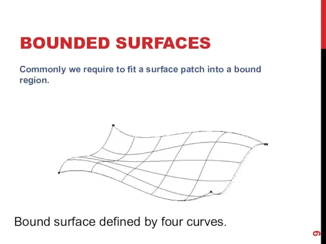
- 9. BOUNDED SURFACES Commonly we require to fit a surface patch into a bound region. Bound surface
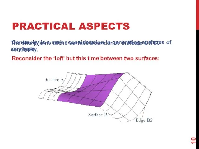
- 10. PRACTICAL ASPECTS Continuity is a major consideration in generating surfaces of any type. Reconsider the ‘loft’
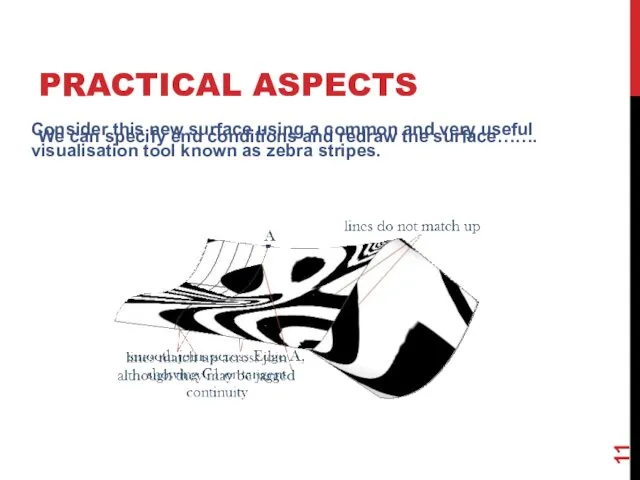
- 11. PRACTICAL ASPECTS We can specify end conditions and redraw the surface……. Consider this new surface using
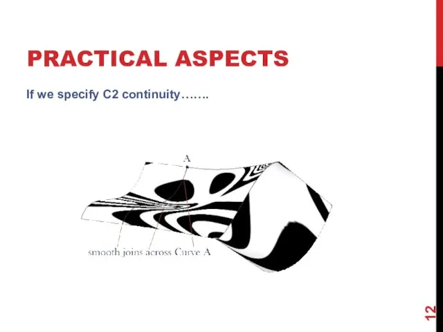
- 12. PRACTICAL ASPECTS If we specify C2 continuity…….
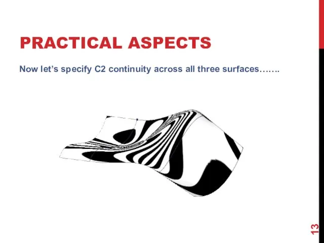
- 13. PRACTICAL ASPECTS Now let’s specify C2 continuity across all three surfaces…….
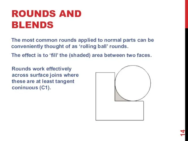
- 14. ROUNDS AND BLENDS The most common rounds applied to normal parts can be conveniently thought of
- 16. Скачать презентацию
SURFACE GEOMETRY
Bezier, basic B-spline and NURBS can all be used to
SURFACE GEOMETRY
Bezier, basic B-spline and NURBS can all be used to

SURFACE GEOMETRY
Perhaps the simplest surface, from a construction point of view,
SURFACE GEOMETRY
Perhaps the simplest surface, from a construction point of view,
SURFACE GEOMETRY
Extending this approach we can create surfaces by moving curves
SURFACE GEOMETRY
Extending this approach we can create surfaces by moving curves
SURFACE GEOMETRY
Normally we use surface patches formulated in NURBS and we
SURFACE GEOMETRY
Normally we use surface patches formulated in NURBS and we
SURFACE GEOMETRY
Surfaces usually come in two forms ie as solids or
SURFACE GEOMETRY
Surfaces usually come in two forms ie as solids or
LOFTING
Lofting joins two or more curves to each other
Curve A
Curve
LOFTING
Lofting joins two or more curves to each other
Curve A
Curve
COMPLEX SWEEPS
More complex sweeps can be formed by combining sweeps and
COMPLEX SWEEPS
More complex sweeps can be formed by combining sweeps and
BOUNDED SURFACES
Commonly we require to fit a surface patch into a
BOUNDED SURFACES
Commonly we require to fit a surface patch into a
PRACTICAL ASPECTS
Continuity is a major consideration in generating surfaces of any
PRACTICAL ASPECTS
Continuity is a major consideration in generating surfaces of any
PRACTICAL ASPECTS
We can specify end conditions and redraw the surface…….
Consider this
PRACTICAL ASPECTS
We can specify end conditions and redraw the surface…….
Consider this
PRACTICAL ASPECTS
If we specify C2 continuity…….
PRACTICAL ASPECTS
If we specify C2 continuity…….
PRACTICAL ASPECTS
Now let’s specify C2 continuity across all three surfaces…….
PRACTICAL ASPECTS
Now let’s specify C2 continuity across all three surfaces…….
ROUNDS AND BLENDS
The most common rounds applied to normal parts can
ROUNDS AND BLENDS
The most common rounds applied to normal parts can
 Системы управления базами данных
 Программная инженерия. Кафедра ВМиК
 Модели представления знаний в интеллектуальных системах
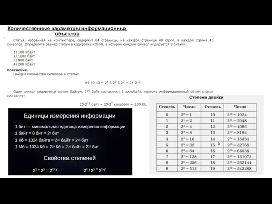 Количественные параметры информационных объектов
 Digital nomads – who are they
 Решение задач с использованием символьных величин и строк символов. Практическая работа №13
 Разработка системы торгового и складского учета
 Урок игра по теме Кодирование числовой информации
 Машина Тьюринга
 Internet Security and Private Information
 Презентация
 Обзор программных средств для звонков через интернет
 Язык программирования общего назначения Python
 Структура IR сайта. Главная страница
 Кодирование звуковой информации
 Передача информации
 Составляющие информационной технологии
 Студия разработки мобильных и web приложений ООО JDG
 Типовое внедрение STORVERK CRM на платформе 1С
 Поиск и представление информации в БД. Сортировка записей. Изменение порядка записей
 Онтология (в информатике)
 Clusters
 Средства защиты информации в ОС Windows и Unix. (Лекция 10)
 Windows Movie Maker
 Решение задач. Кодирование и операции над числами в разных системах счисления.
 Использование ИКТ на уроках русского языка и литературы
 Базовый инструментарий специалиста по тестированию
 Нейронные сети