- Training Manual

Содержание
- 2. Ⅰ. Specification Ⅱ. Design Ⅲ. Inner Feature Ⅳ. Disassemble Ⅴ. Troubleshooting Ⅵ. 12Year New Smart TV
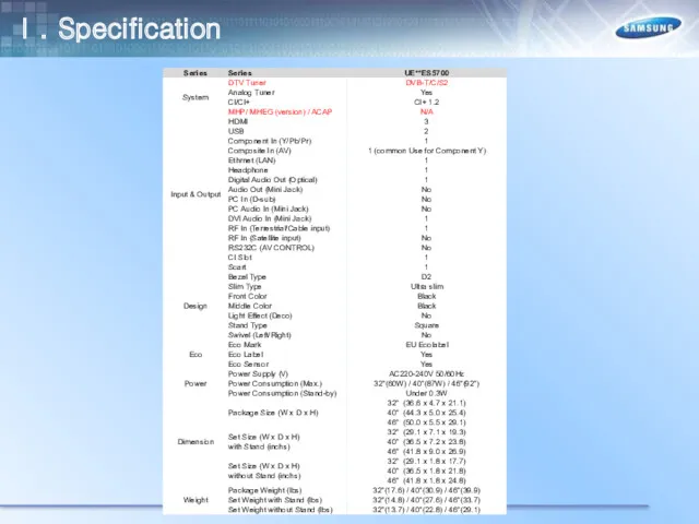
- 3. Ⅰ. Specification
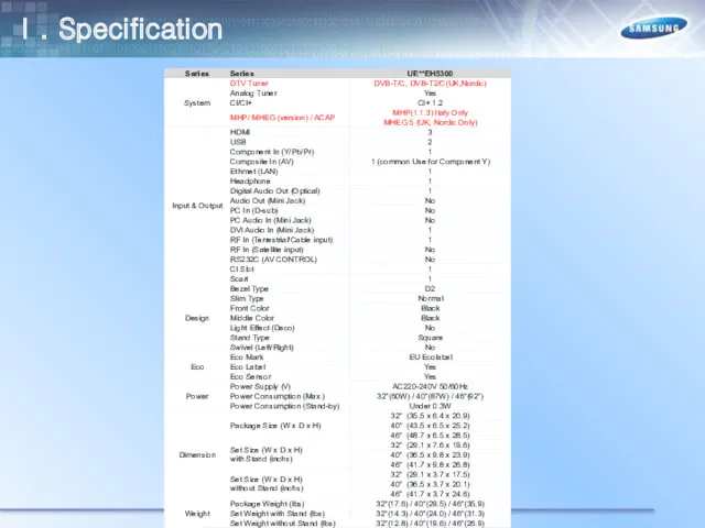
- 4. Ⅰ. Specification
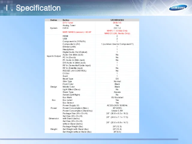
- 5. Ⅰ. Specification
- 6. Ⅰ. Specification
- 7. Ⅰ. Specification
- 8. Ⅰ. Specification
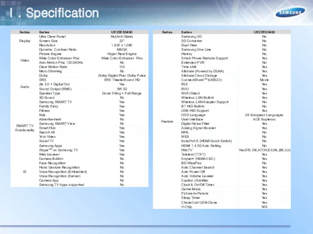
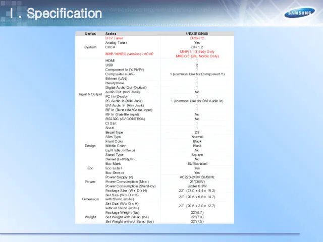
- 9. Ⅰ. Specification
- 10. Ⅰ. Specification
- 11. Ⅰ. Specification
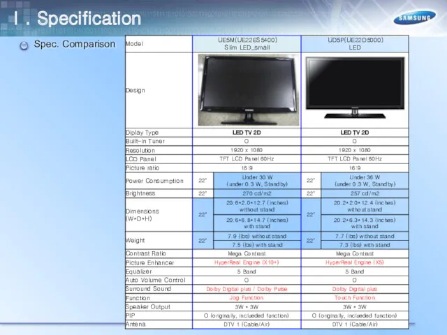
- 12. Spec. Comparison Ⅰ. Specification
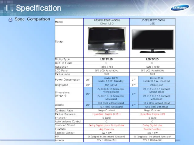
- 13. Spec. Comparison Ⅰ. Specification
- 14. Spec. Comparison Ⅰ. Specification
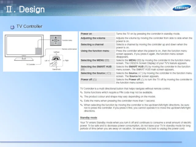
- 15. Ⅱ. Design TV Controller
- 16. Initial Setup Ⅱ. Design
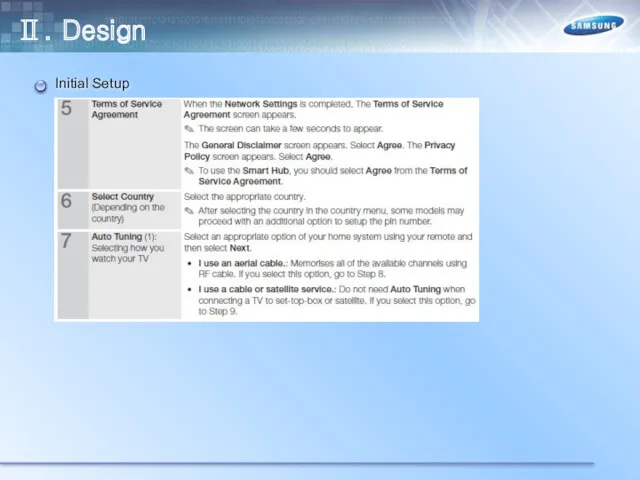
- 17. Initial Setup Ⅱ. Design
- 18. Initial Setup Ⅱ. Design
- 19. Reset (Self Diagnosis) Ⅱ. Design
- 20. Connection (for more information, refer to Connecting the TV in the E-Manual) According to Model, connection
- 21. Connecting to a COMMON INTERFACE slot Ⅱ. Design
- 22. Changing the Input Source Ⅱ. Design
- 23. Network Connection Ⅱ. Design
- 24. Network Connection Ⅱ. Design
- 25. Display Resolution Ⅱ. Design
- 26. Remote Control(TM1250) Ⅱ. Design
- 27. Remote Control(TM1250) Italy (MHP Only) Ⅱ. Design
- 28. Front - IR Sensor - Power Indicator - Jog Function - Speakers E5500/5700 Ⅱ. Design
- 29. Rear - UE32ES5500(5700) Ⅱ. Design
- 30. Rear – UE40ES5500(5700) UE46ES5500(5700) Ⅱ. Design
- 31. Jack panel detail / Rear view Those Model' In-Lays are Cover carved . But, Componets part
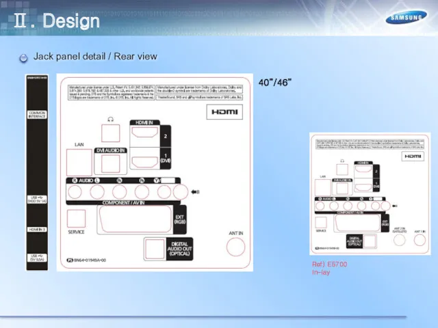
- 32. Jack panel detail / Rear view Ⅱ. Design
- 33. Front - IR Sensor - Power Indicator - Jog Function - Speakers E5300 Ⅱ. Design
- 34. Rear - UE32EH5300 UE40EH5300 Ⅱ. Design
- 35. Rear – UE46EH5300 Ⅱ. Design
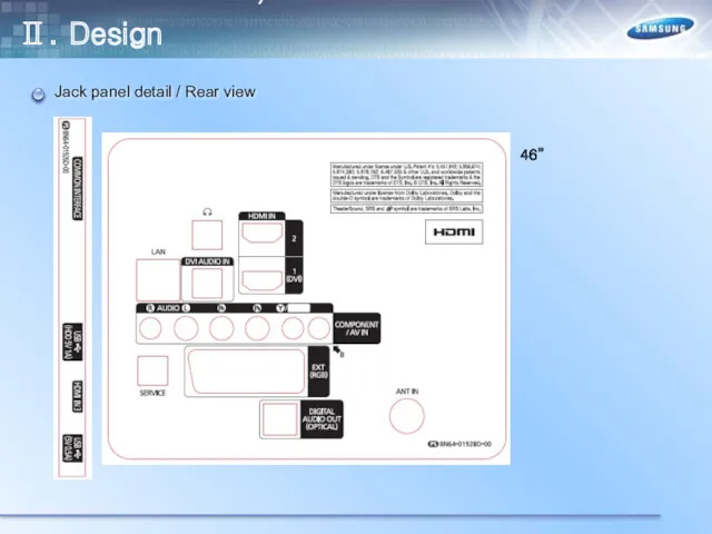
- 36. Jack panel detail / Rear view Ⅱ. Design UE5300 46" W.Europe(T/C) / UK,Nordic(T2/C) UE5300 32"/40" W.Europe(T/C)
- 37. Jack panel detail / Rear view Ⅱ. Design UE5300 46" W.Europe(T/C) / UK,Nordic(T2/C) UE5300 32"/40" W.Europe(T/C)
- 38. Front - IR Sensor - Power Indicator - Jog Function - Speakers E4500 Ⅱ. Design -
- 39. Rear – UE26EH4500 Ⅱ. Design
- 40. Jack panel detail / Rear view Those Model' In-Lays are Cover carved . But, Componets part
- 41. Front - IR Sensor - Power Indicator - Jog Function - Speakers E5400 Ⅱ. Design -
- 42. Rear – UE22ES5400 Ⅱ. Design
- 43. Jack panel detail / Rear view Those Model' In-Lays are Cover carved . But, Componets part
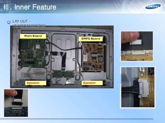
- 44. Ⅲ. Inner Feature LAY OUT – UE32ES5500(5700) Main Board SMPS Board Speaker (L) Speaker (R)
- 45. LAY OUT – UE40ES5500(5700) Main Board SMPS Board Speaker (L) Speaker (R) Ⅲ. Inner Feature
- 46. LAY OUT – UE46ES5500(5700) Main Board SMPS Board Speaker (L) Speaker (R) Ⅲ. Inner Feature
- 47. LAY OUT – UE32EH5300 Main Board SMPS Board Speaker (L) Speaker (R) Ⅲ. Inner Feature
- 48. LAY OUT – UE40EH5300 Main Board SMPS Board Speaker (L) Speaker (R) Ⅲ. Inner Feature
- 49. LAY OUT – UE46EH5300 Main Board SMPS Board Speaker (L) Speaker (R) Ⅲ. Inner Feature
- 50. LAY OUT – UE26EH4500 Main Board SMPS Board Speaker (L) Speaker (R) Ⅲ. Inner Feature
- 51. LAY OUT – UE22ES5400 Main Board SMPS Board Speaker (L) Speaker (R) Ⅲ. Inner Feature
- 52. Wiring Diagram E5500(5700), E5300 Ⅲ. Inner Feature
- 53. Wiring Diagram WiFi E4500 Ⅲ. Inner Feature
- 54. Wiring Diagram E5400 T-CON Main Board IP Board CN202 CN1401 CN1202 CN302 CNM803 Speaker Speaker WiFi
- 55. X10+ Block-diagram PC_DVI_L/R_IN AV1_CVBS HDMIx_RX (CEC/ARC) SEMS27 (Mstar X10+) Micro-processor (@900MHz) Transport Stream De-multiplexer MPEG2(HD) MPEG4(HD)
- 56. Power Tree RMS(mA)/ MAX(mA) / PEAK(mA) HDMI 1080/60i + PIP(H.264 ch) + OSD ON Ⅲ. Inner
- 57. Reset Tree STB_NRESET SYS_HRESET NRESET_OUT TUNER_NRESET SW_INVERTER pRESET USB_HUB_NRESET USB HUB PCM_RESET SW_POWER POWER_DET TUNER PCM
- 58. I2C Tree X10+ GPIO56 GPIO55 SUB MICOM IC301 NTP7412 (0x54) DDCA_CK DDCA_KA GPIO108 GPIO109 DDCA_CK DDCA_DA
- 59. UART Tree RDB_FANET TDB_FANET RDA_MICOM TDA_MICOM SUB MICOM SP3232 RDB_DEBUG TDB_DEBUG CN1203 (Debug option) ISP_TX/TXD0 ISP_RX/RXD0
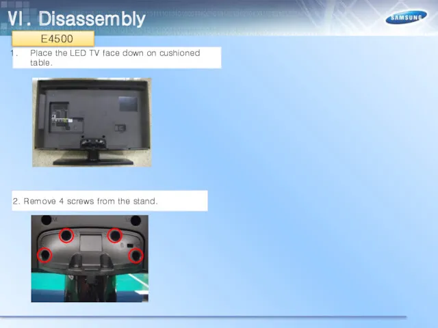
- 60. Ⅵ. Disassembly Place the LED TV face down on cushioned table. 2. Remove 4 screws from
- 61. 3. Remove stand. 4. 32" : Remove 1 screw of cover jack and 1 screw of
- 62. 5. 32" : Remove the cover jack 40”/46" : Remove the rear cover. 6. Disconnect the
- 63. 7. Remove the screws of middle-cover. 8. Remove the middle-cover. 32”(11ea) 40”(14ea) 46”(19ea) 32” 40”/46” Ⅵ.
- 64. 9.Remove the screws of main board and Power board. 10. Remove the speakers and power cables.
- 65. 11. Remove the LVDS cable and Panel drive cable. 12. Completed disassembly. Ⅵ. Disassembly
- 66. Place the LED TV face down on cushioned table. 2. Remove 4 screws from the stand.
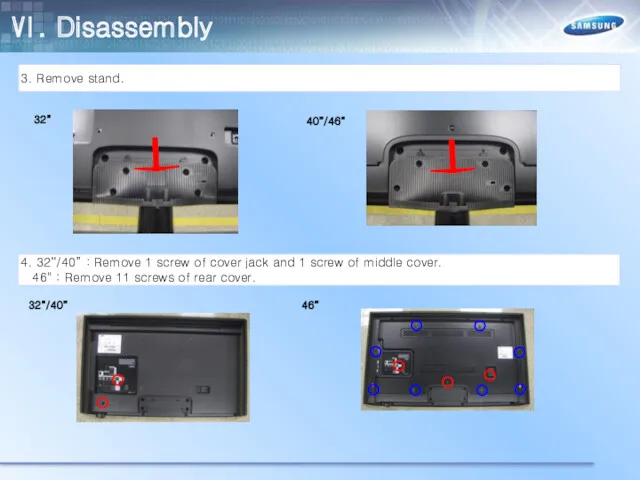
- 67. 3. Remove stand. 4. 32“/40” : Remove 1 screw of cover jack and 1 screw of
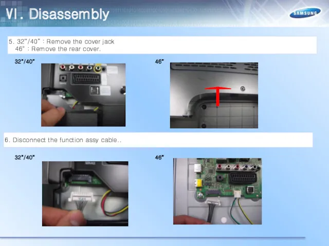
- 68. 5. 32“/40” : Remove the cover jack 46" : Remove the rear cover. 6. Disconnect the
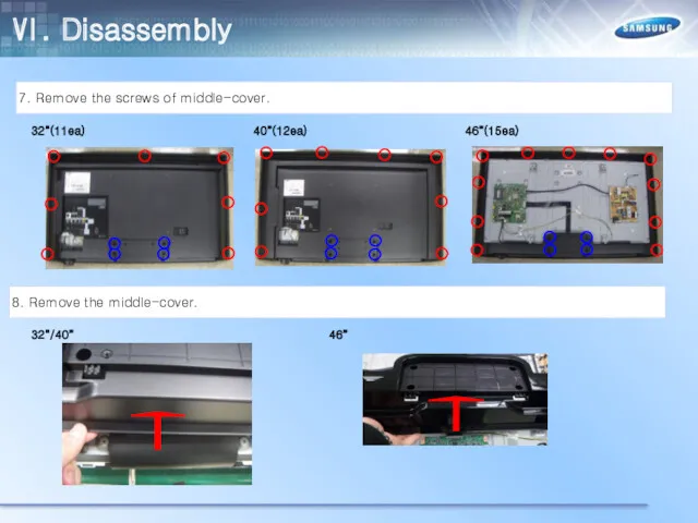
- 69. 7. Remove the screws of middle-cover. 8. Remove the middle-cover. 32”(11ea) 40”(12ea) 46”(15ea) 32”/40” 46” Ⅵ.
- 70. 9.Remove 15 screws of Main board, Power board, Bracket Wall. 10. Remove the speakers and power
- 71. 11. Remove the LVDS cable and Panel drive cable. 12. Remove the Bracket-Wall Ⅵ. Disassembly
- 72. 13. Completed disassembly. Ⅵ. Disassembly
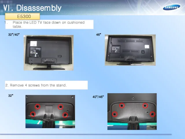
- 73. Place the LED TV face down on cushioned table. 2. Remove 4 screws from the stand.
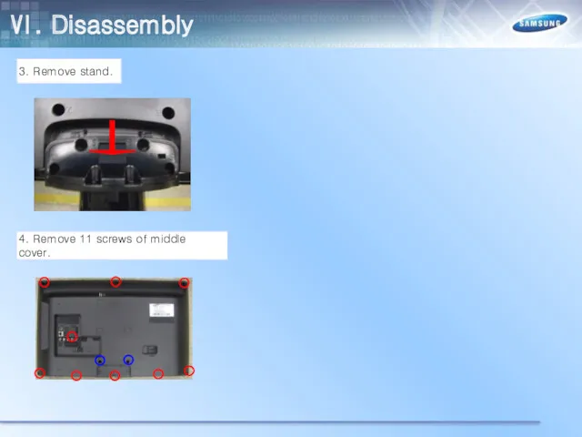
- 74. 3. Remove stand. 4. Remove 11 screws of middle cover. Ⅵ. Disassembly
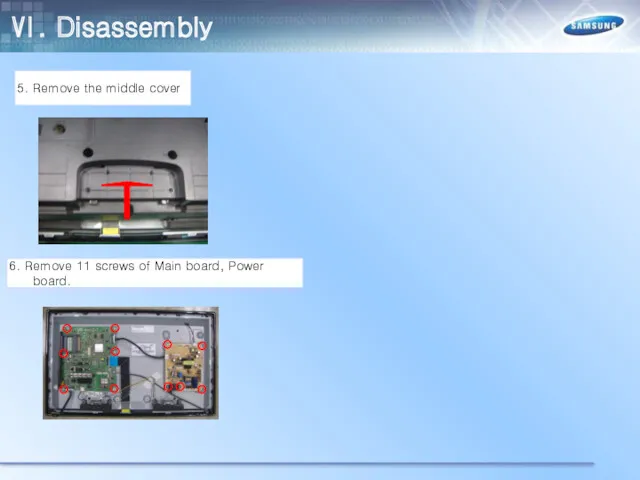
- 75. 5. Remove the middle cover 6. Remove 11 screws of Main board, Power board. Ⅵ. Disassembly
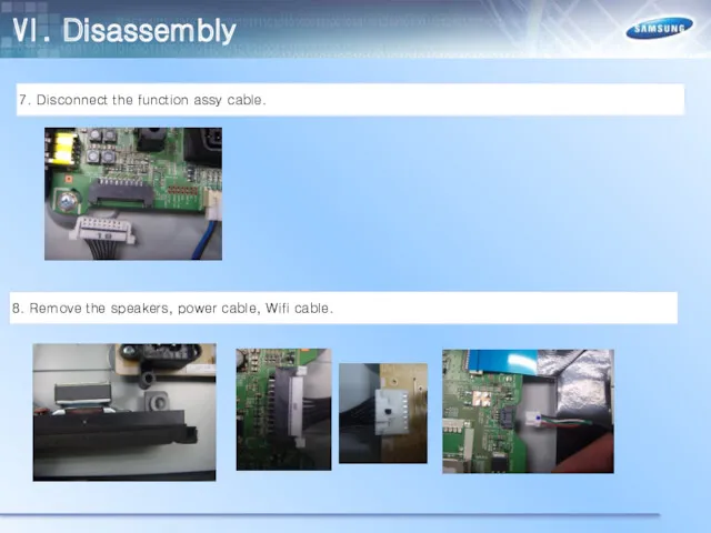
- 76. 7. Disconnect the function assy cable. 8. Remove the speakers, power cable, Wifi cable. Ⅵ. Disassembly
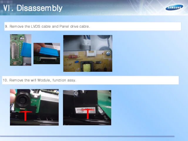
- 77. 9. Remove the LVDS cable and Panel drive cable. 10. Remove the wifi Module, function assy.
- 78. 11. Remove the the front cover. 12. Completed disassembly Ⅵ. Disassembly
- 79. Place the LED TV face down on cushioned table. 2. Remove 3 screws from the stand
- 80. 3. Remove 5 screws of rear cover. 4. Remove the middle cover. Ⅵ. Disassembly
- 81. 5. Disconnect the LVDS cable, Panel drive cable, function assy. 6. Remove 7 screws of Main
- 82. 7. Disconnect cables(Power, Speaker, Wifi) CF> If you want to change the only panel, you don’t
- 83. 8. Lift up the panel. 9. Completed disassembly Ⅵ. Disassembly
- 84. Check List for Initial operation Main Board Power Board Power Cable LVDS Ⅴ. Trouble Shooting T-con
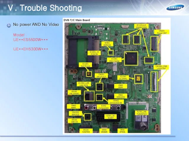
- 85. Ⅴ. Trouble Shooting No power AND No Video Model : UE**ES5500W*** UE**EH5300W***
- 86. Ⅴ. Trouble Shooting No power AND No Video Model : UE**ES5500K*** UE**EH5300K*** Model : UE**E5700S***
- 87. Ⅴ. Trouble Shooting No power AND No Video Model : UE26EH4500W*** Model : UE22ES5400W***
- 88. Ⅴ. Trouble Shooting – No Power This Troubleshooting is based on E5500(5700) Model. So, Please Other
- 89. Ⅴ. Trouble Shooting – No Power
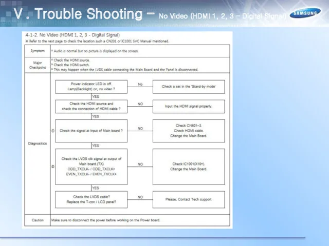
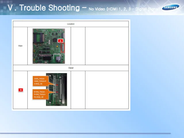
- 90. Ⅴ. Trouble Shooting – No Video (HDMI 1, 2, 3 - Digital Signal)
- 91. Ⅴ. Trouble Shooting – No Video (HDMI 1, 2, 3 - Digital Signal)
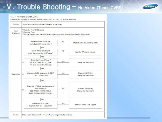
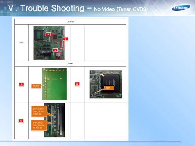
- 92. Ⅴ. Trouble Shooting – No Video (Tuner_CVBS)
- 93. Ⅴ. Trouble Shooting – No Video (Tuner_CVBS)
- 94. Ⅴ. Trouble Shooting – No Video (Tuner DTV)
- 95. Ⅴ. Trouble Shooting – No Video (Tuner DTV)
- 96. Ⅴ. Trouble Shooting – No Video (Video AV)
- 97. Ⅴ. Trouble Shooting – No Video (Video AV)
- 98. Ⅴ. Trouble Shooting – No Video (Component)
- 99. Ⅴ. Trouble Shooting – No Video (Component)
- 100. Ⅴ. Trouble Shooting – No Sound(Speaker/Headphone_out/Optical)
- 101. Ⅴ. Trouble Shooting – No Sound(Speaker/Headphone_out/Optical)
- 102. Ⅴ. Trouble Shooting Calibration
- 103. Ⅴ. Trouble Shooting Calibration
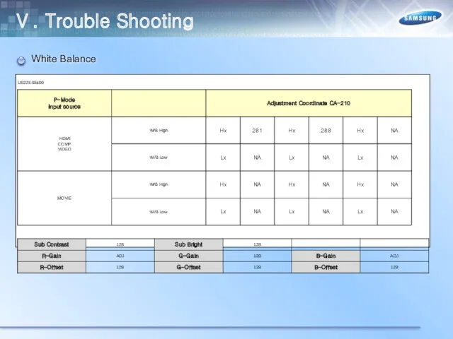
- 104. Ⅴ. Trouble Shooting White Balance
- 105. Ⅴ. Trouble Shooting White Balance
- 106. Ⅴ. Trouble Shooting White Balance
- 107. Ⅵ. Trouble Shooting White Balance
- 108. Ⅵ. Trouble Shooting White Balance
- 109. Ⅵ. Trouble Shooting White Balance
- 110. Ⅴ. Trouble Shooting White Balance
- 111. White Balance Ⅴ. Trouble Shooting
- 112. White Balance Ⅴ. Trouble Shooting
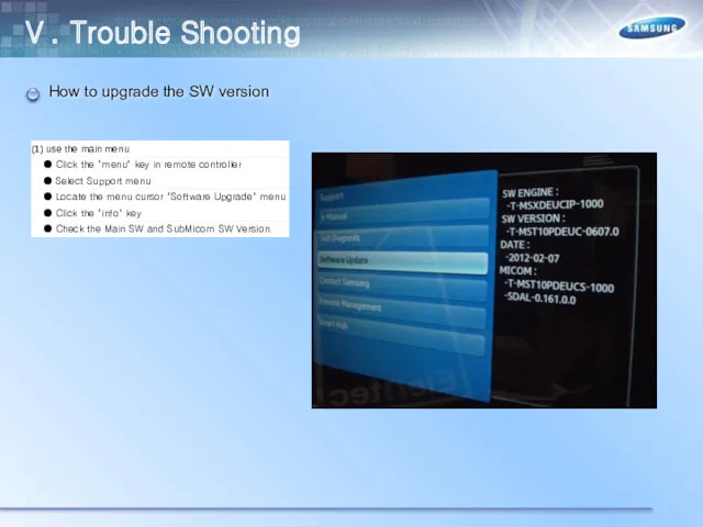
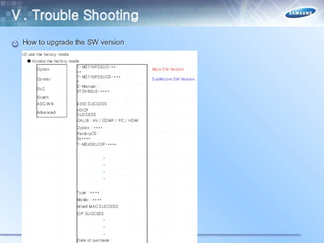
- 113. How to upgrade the SW version Ⅴ. Trouble Shooting
- 114. How to upgrade the SW version Ⅴ. Trouble Shooting
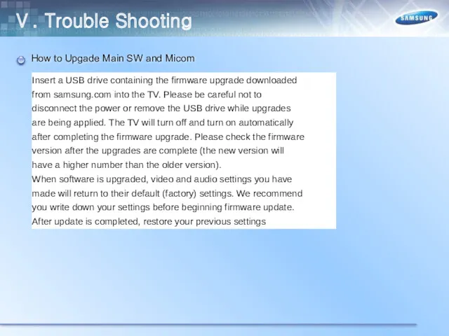
- 115. How to Upgade Main SW and Micom Ⅴ. Trouble Shooting
- 116. How to Upgrade Main SW Ⅴ. Trouble Shooting
- 117. How to Upgrade Main SW Ⅴ. Trouble Shooting
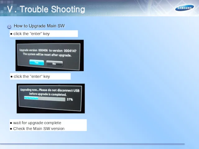
- 118. How to Upgrade Main SW Ⅴ. Trouble Shooting
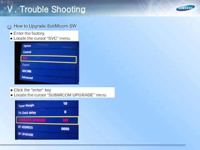
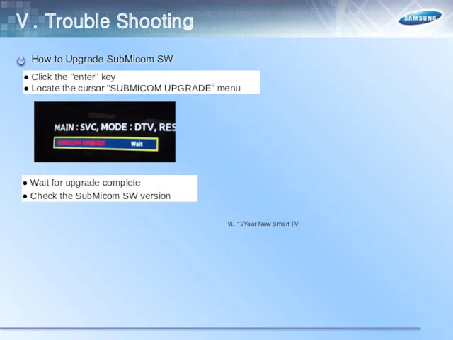
- 119. How to Upgrade SubMicom SW Ⅴ. Trouble Shooting
- 120. How to Upgrade SubMicom SW Ⅴ. Trouble Shooting
- 121. How to Upgrade SubMicom SW Ⅵ. 12Year New Smart TV Ⅴ. Trouble Shooting
- 122. 2012 SMART TV New Fuction Ⅵ. 12Year New SMART TV
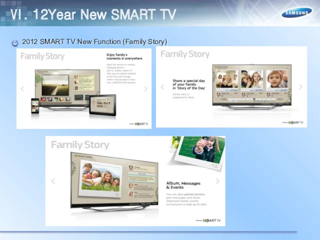
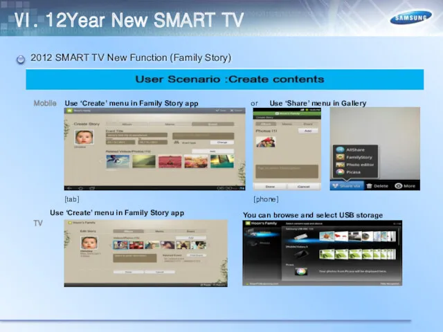
- 123. 2012 SMART TV New Function (Family Story) Ⅵ. 12Year New SMART TV
- 124. 2012 SMART TV New Function (Family Story) Ⅵ. 12Year New SMART TV
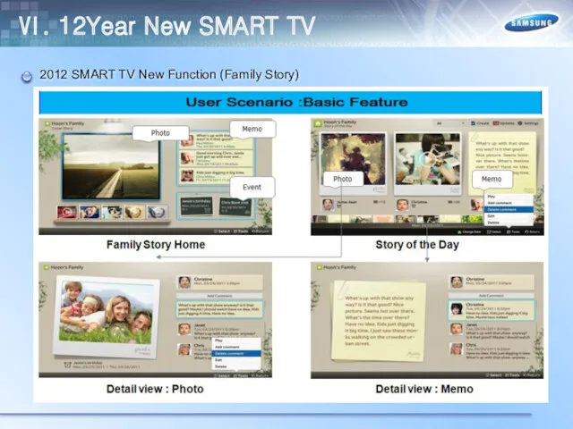
- 125. 2012 SMART TV New Function (Family Story) Ⅵ. 12Year New SMART TV
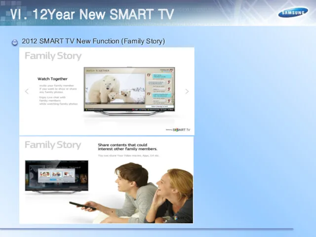
- 126. 2012 SMART TV New Fuction (Family Story) Ⅵ. 12Year New SMART TV
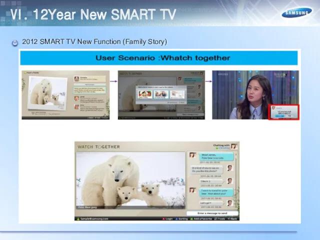
- 127. 2012 SMART TV New Function (Family Story) Ⅵ. 12Year New SMART TV
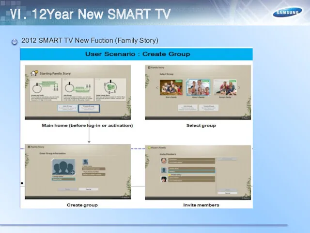
- 128. 2012 SMART TV New Function (Family Story) Ⅵ. 12Year New SMART TV
- 129. 2012 SMART TV New Function (Family Story) Ⅵ. 12Year New SMART TV
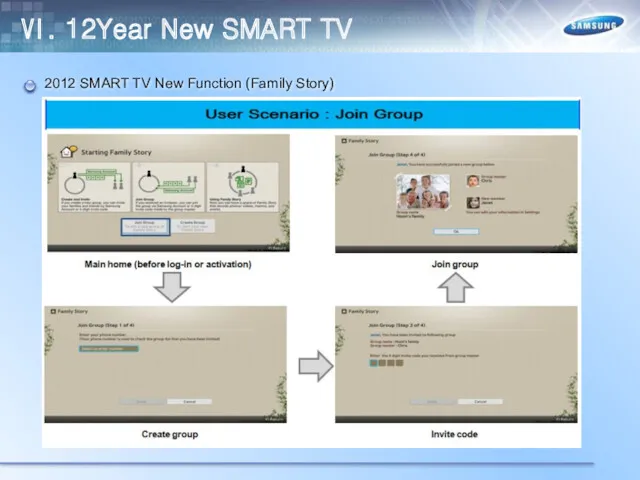
- 130. 2012 SMART TV New Function (Family Story) Ⅵ. 12Year New SMART TV
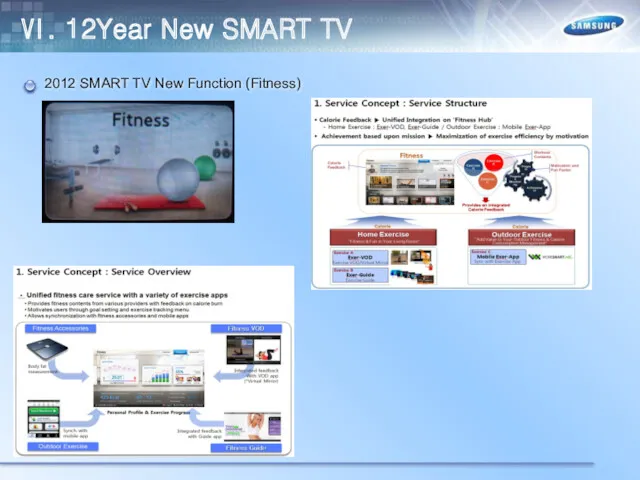
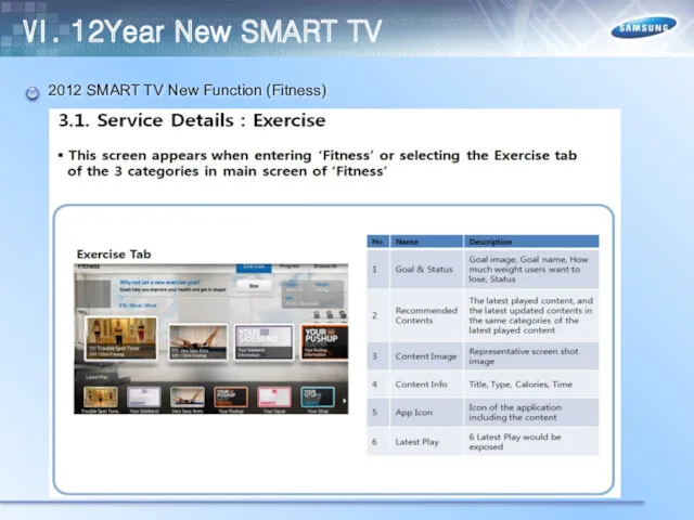
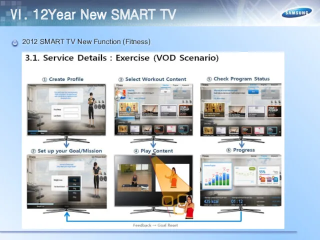
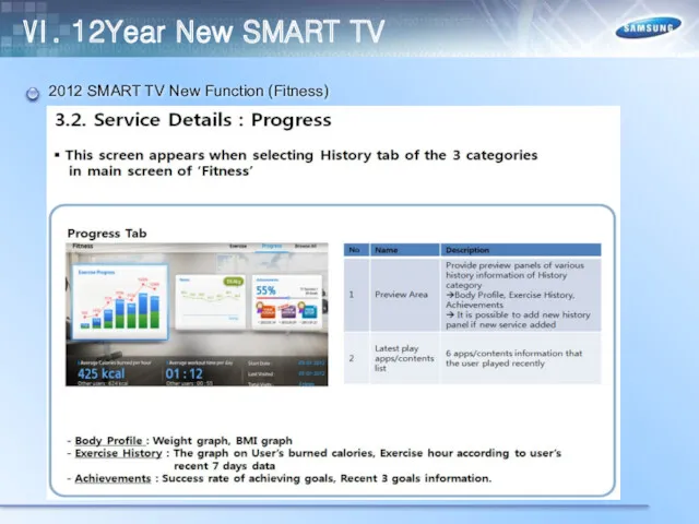
- 131. 2012 SMART TV New Function (Fitness) Ⅵ. 12Year New SMART TV
- 132. 2012 SMART TV New Function (Fitness) Ⅵ. 12Year New SMART TV
- 133. 2012 SMART TV New Function (Fitness) Ⅵ. 12Year New SMART TV
- 134. 2012 SMART TV New Function (Fitness) Ⅵ. 12Year New SMART TV
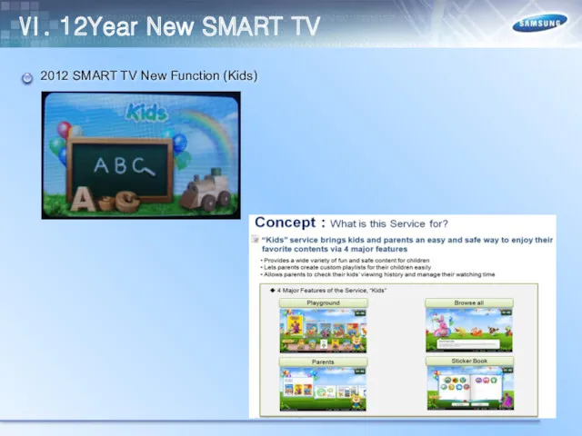
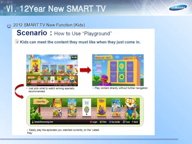
- 135. 2012 SMART TV New Function (Kids) Ⅵ. 12Year New SMART TV
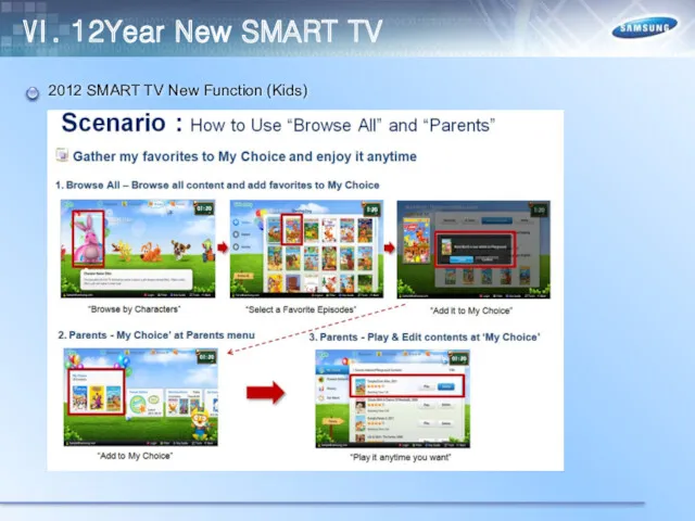
- 136. 2012 SMART TV New Function (Kids) Ⅵ. 12Year New SMART TV
- 137. 2012 SMART TV New Function (Kids) Ⅵ. 12Year New SMART TV
- 139. Скачать презентацию
Ⅰ. Specification
Ⅱ. Design
Ⅲ. Inner Feature
Ⅳ. Disassemble
Ⅴ. Troubleshooting
Ⅵ. 12Year New Smart TV
Ⅰ. Specification
Ⅱ. Design
Ⅲ. Inner Feature
Ⅳ. Disassemble
Ⅴ. Troubleshooting
Ⅵ. 12Year New Smart TV

Ⅰ. Specification
Ⅰ. Specification

Ⅰ. Specification
Ⅰ. Specification
Ⅰ. Specification
Ⅰ. Specification

Ⅰ. Specification
Ⅰ. Specification
Ⅰ. Specification
Ⅰ. Specification

Ⅰ. Specification
Ⅰ. Specification
Ⅰ. Specification
Ⅰ. Specification
Ⅰ. Specification
Ⅰ. Specification
Ⅰ. Specification
Ⅰ. Specification
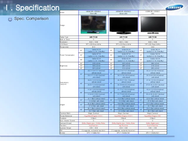
Spec. Comparison
Ⅰ. Specification
Spec. Comparison
Ⅰ. Specification
Spec. Comparison
Ⅰ. Specification
Spec. Comparison
Ⅰ. Specification
Spec. Comparison
Ⅰ. Specification
Spec. Comparison
Ⅰ. Specification
Ⅱ. Design
TV Controller
Ⅱ. Design
TV Controller
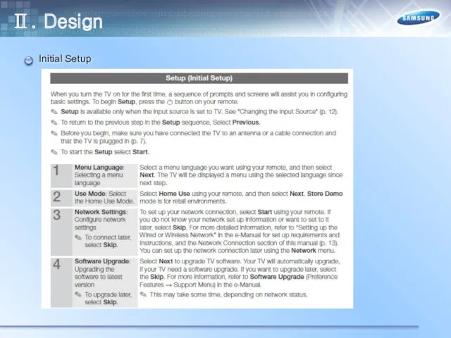
Initial Setup
Ⅱ. Design
Initial Setup
Ⅱ. Design
Initial Setup
Ⅱ. Design
Initial Setup
Ⅱ. Design
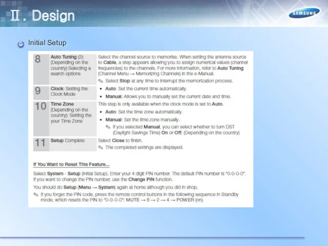
Initial Setup
Ⅱ. Design
Initial Setup
Ⅱ. Design
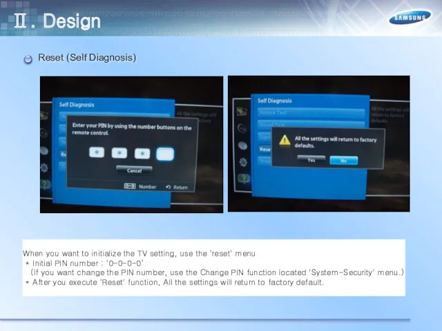
Reset (Self Diagnosis)
Ⅱ. Design
Reset (Self Diagnosis)
Ⅱ. Design
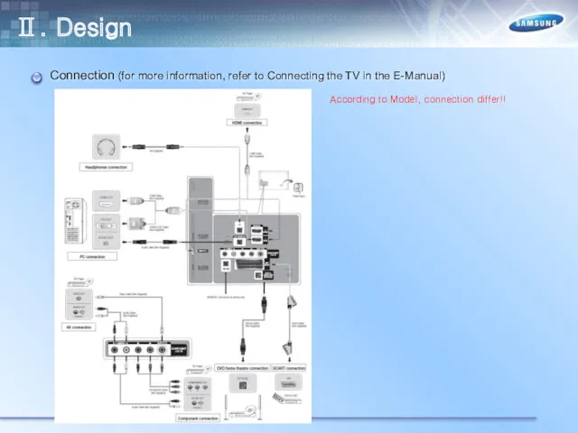
Connection (for more information, refer to Connecting the TV in the
Connection (for more information, refer to Connecting the TV in the
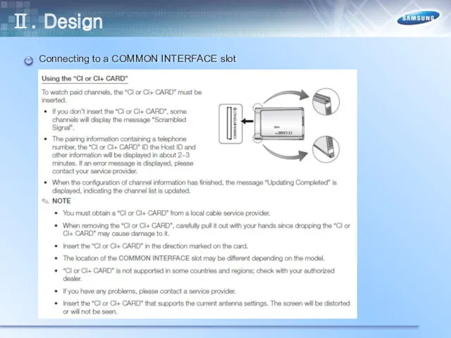
Connecting to a COMMON INTERFACE slot
Ⅱ. Design
Connecting to a COMMON INTERFACE slot
Ⅱ. Design
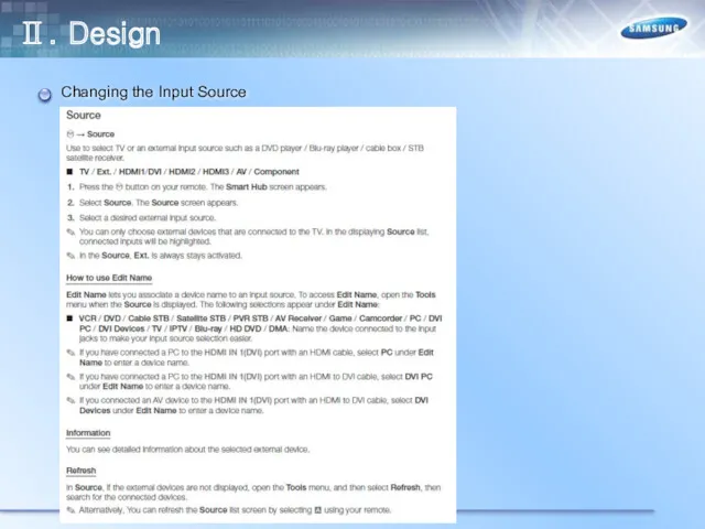
Changing the Input Source
Ⅱ. Design
Changing the Input Source
Ⅱ. Design
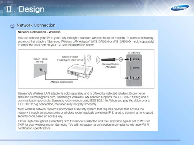
Network Connection
Ⅱ. Design
Network Connection
Ⅱ. Design
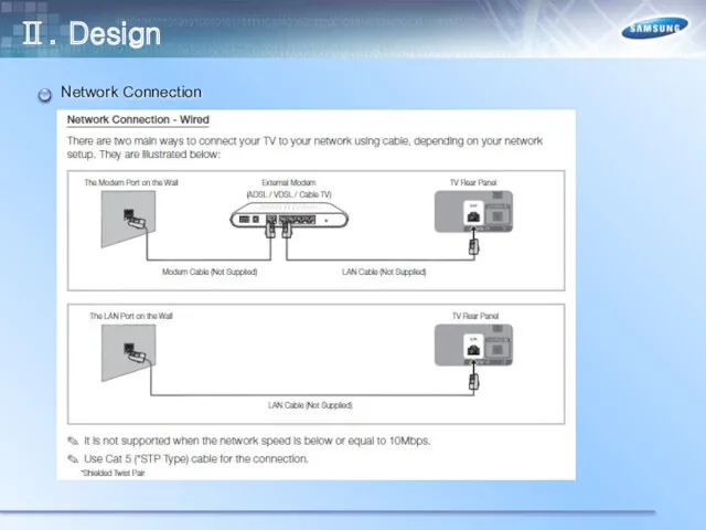
Network Connection
Ⅱ. Design
Network Connection
Ⅱ. Design
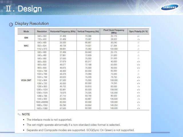
Display Resolution
Ⅱ. Design
Display Resolution
Ⅱ. Design
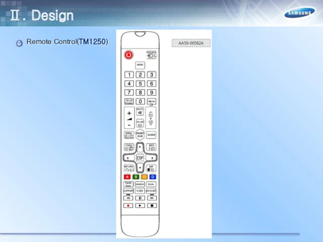
Remote Control(TM1250)
Ⅱ. Design
Remote Control(TM1250)
Ⅱ. Design
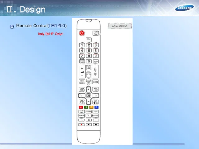
Remote Control(TM1250)
Italy (MHP Only)
Ⅱ. Design
Remote Control(TM1250)
Italy (MHP Only)
Ⅱ. Design
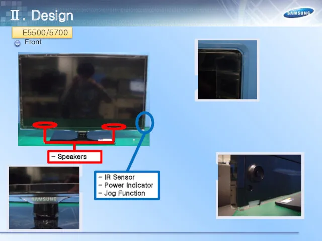
Front
- IR Sensor
- Power Indicator
- Jog Function
- Speakers
E5500/5700
Ⅱ. Design
Front
- IR Sensor
- Power Indicator
- Jog Function
- Speakers
E5500/5700
Ⅱ. Design
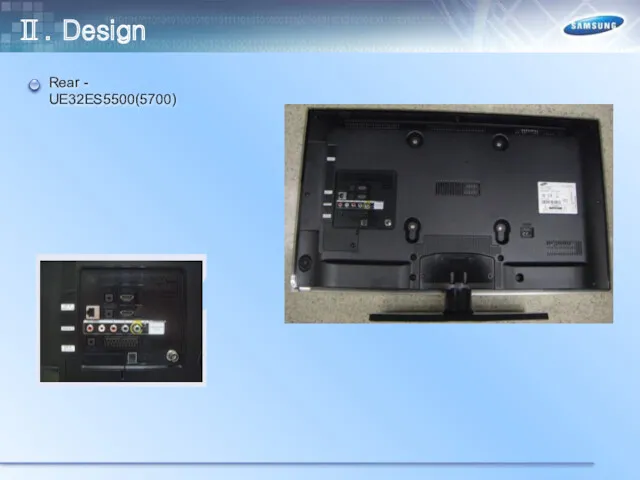
Rear - UE32ES5500(5700)
Ⅱ. Design
Rear - UE32ES5500(5700)
Ⅱ. Design
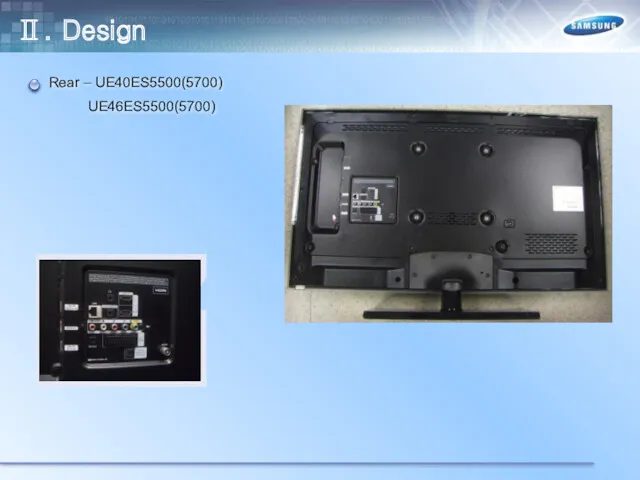
Rear – UE40ES5500(5700)
UE46ES5500(5700)
Ⅱ. Design
Rear – UE40ES5500(5700)
UE46ES5500(5700)
Ⅱ. Design
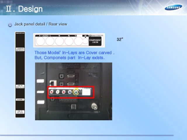
Jack panel detail / Rear view
Those Model' In-Lays are Cover carved
Jack panel detail / Rear view
Those Model' In-Lays are Cover carved
Jack panel detail / Rear view
Ⅱ. Design
Jack panel detail / Rear view
Ⅱ. Design
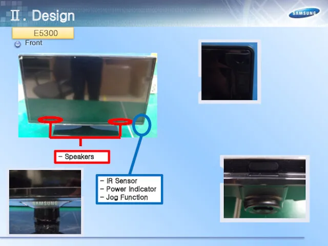
Front
- IR Sensor
- Power Indicator
- Jog Function
- Speakers
E5300
Ⅱ. Design
Front
- IR Sensor
- Power Indicator
- Jog Function
- Speakers
E5300
Ⅱ. Design
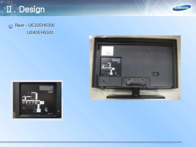
Rear - UE32EH5300
UE40EH5300
Ⅱ. Design
Rear - UE32EH5300
UE40EH5300
Ⅱ. Design
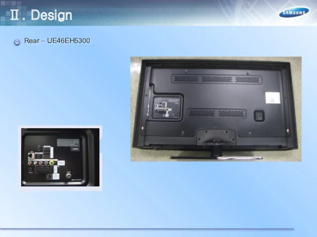
Rear – UE46EH5300
Ⅱ. Design
Rear – UE46EH5300
Ⅱ. Design
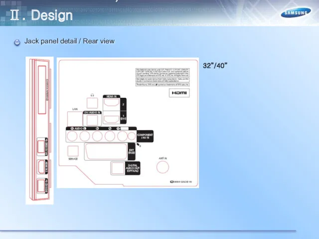
Jack panel detail / Rear view
Ⅱ. Design
UE5300 46"
W.Europe(T/C) / UK,Nordic(T2/C)
UE5300 32"/40"
W.Europe(T/C)
Jack panel detail / Rear view
Ⅱ. Design
UE5300 46"
W.Europe(T/C) / UK,Nordic(T2/C)
UE5300 32"/40"
W.Europe(T/C)
Jack panel detail / Rear view
Ⅱ. Design
UE5300 46"
W.Europe(T/C) / UK,Nordic(T2/C)
UE5300 32"/40"
W.Europe(T/C)
Jack panel detail / Rear view
Ⅱ. Design
UE5300 46"
W.Europe(T/C) / UK,Nordic(T2/C)
UE5300 32"/40"
W.Europe(T/C)
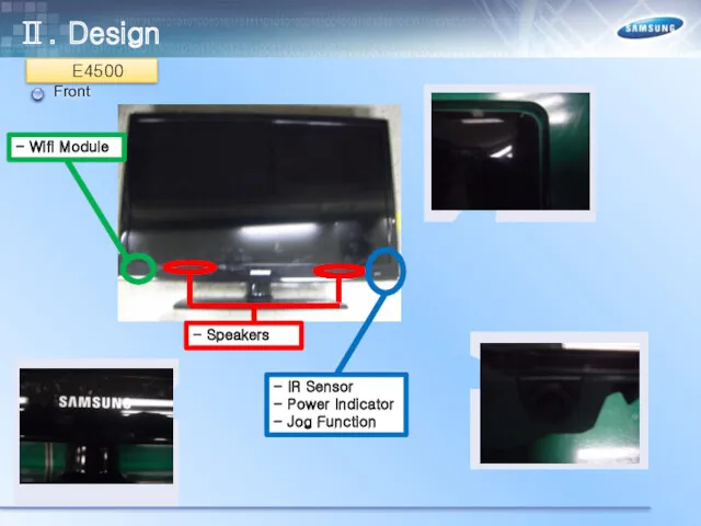
Front
- IR Sensor
- Power Indicator
- Jog Function
- Speakers
E4500
Ⅱ. Design
- Wifi Module
Front
- IR Sensor
- Power Indicator
- Jog Function
- Speakers
E4500
Ⅱ. Design
- Wifi Module
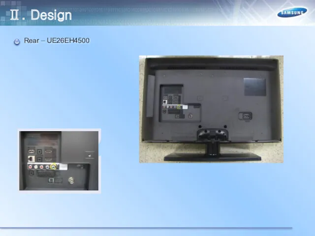
Rear – UE26EH4500
Ⅱ. Design
Rear – UE26EH4500
Ⅱ. Design
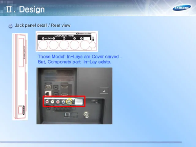
Jack panel detail / Rear view
Those Model' In-Lays are Cover carved
Jack panel detail / Rear view
Those Model' In-Lays are Cover carved
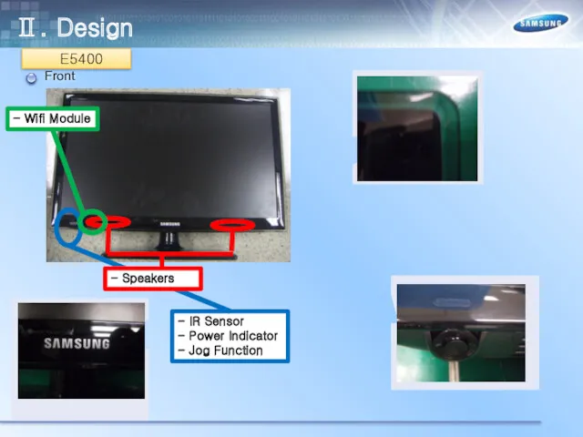
Front
- IR Sensor
- Power Indicator
- Jog Function
- Speakers
E5400
Ⅱ. Design
- Wifi Module
Front
- IR Sensor
- Power Indicator
- Jog Function
- Speakers
E5400
Ⅱ. Design
- Wifi Module
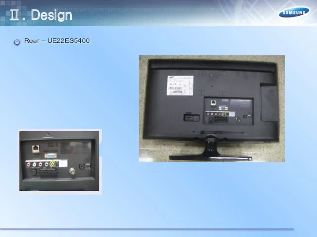
Rear – UE22ES5400
Ⅱ. Design
Rear – UE22ES5400
Ⅱ. Design
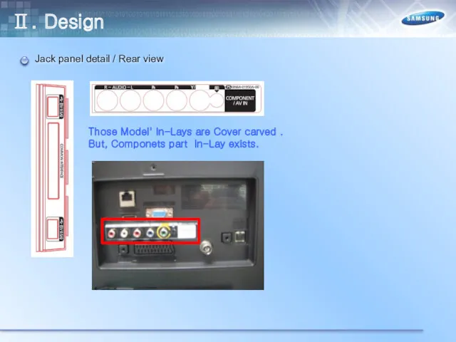
Jack panel detail / Rear view
Those Model' In-Lays are Cover carved
Jack panel detail / Rear view
Those Model' In-Lays are Cover carved
Ⅲ. Inner Feature
LAY OUT – UE32ES5500(5700)
Main Board
SMPS Board
Speaker (L)
Speaker (R)
Ⅲ. Inner Feature
LAY OUT – UE32ES5500(5700)
Main Board
SMPS Board
Speaker (L)
Speaker (R)
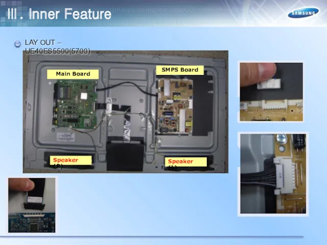
LAY OUT – UE40ES5500(5700)
Main Board
SMPS Board
Speaker (L)
Speaker (R)
Ⅲ. Inner Feature
LAY OUT – UE40ES5500(5700)
Main Board
SMPS Board
Speaker (L)
Speaker (R)
Ⅲ. Inner Feature
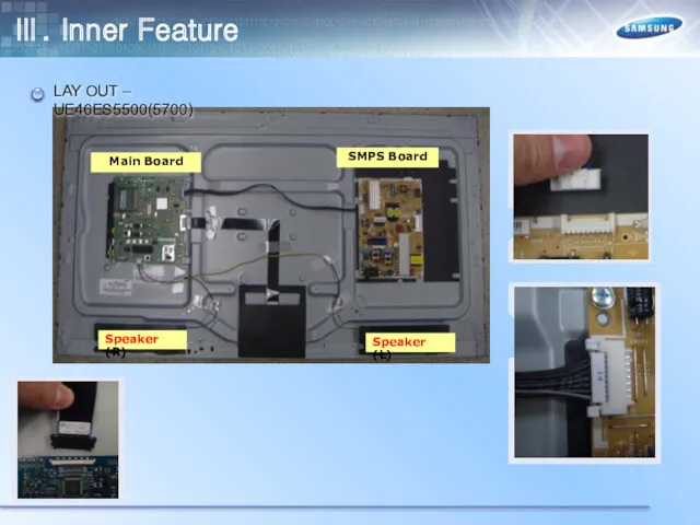
LAY OUT – UE46ES5500(5700)
Main Board
SMPS Board
Speaker (L)
Speaker (R)
Ⅲ. Inner Feature
LAY OUT – UE46ES5500(5700)
Main Board
SMPS Board
Speaker (L)
Speaker (R)
Ⅲ. Inner Feature
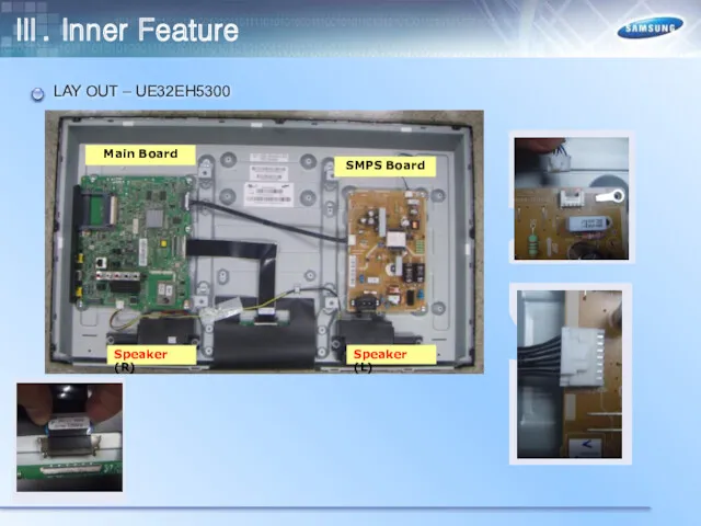
LAY OUT – UE32EH5300
Main Board
SMPS Board
Speaker (L)
Speaker (R)
Ⅲ. Inner Feature
LAY OUT – UE32EH5300
Main Board
SMPS Board
Speaker (L)
Speaker (R)
Ⅲ. Inner Feature
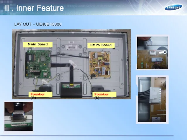
LAY OUT – UE40EH5300
Main Board
SMPS Board
Speaker (L)
Speaker (R)
Ⅲ. Inner Feature
LAY OUT – UE40EH5300
Main Board
SMPS Board
Speaker (L)
Speaker (R)
Ⅲ. Inner Feature
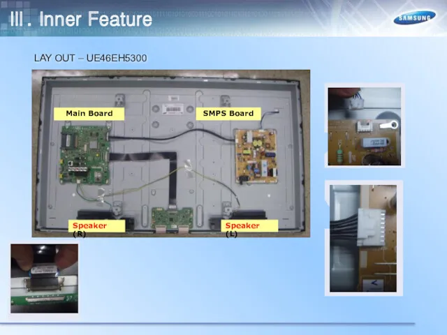
LAY OUT – UE46EH5300
Main Board
SMPS Board
Speaker (L)
Speaker (R)
Ⅲ. Inner Feature
LAY OUT – UE46EH5300
Main Board
SMPS Board
Speaker (L)
Speaker (R)
Ⅲ. Inner Feature
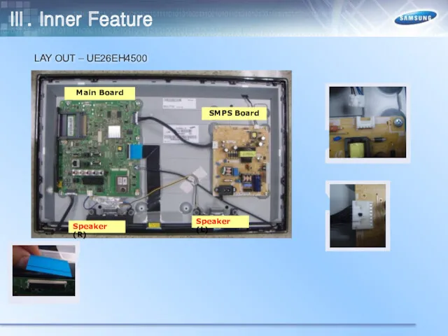
LAY OUT – UE26EH4500
Main Board
SMPS Board
Speaker (L)
Speaker (R)
Ⅲ. Inner Feature
LAY OUT – UE26EH4500
Main Board
SMPS Board
Speaker (L)
Speaker (R)
Ⅲ. Inner Feature
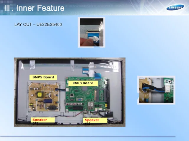
LAY OUT – UE22ES5400
Main Board
SMPS Board
Speaker (L)
Speaker (R)
Ⅲ. Inner Feature
LAY OUT – UE22ES5400
Main Board
SMPS Board
Speaker (L)
Speaker (R)
Ⅲ. Inner Feature
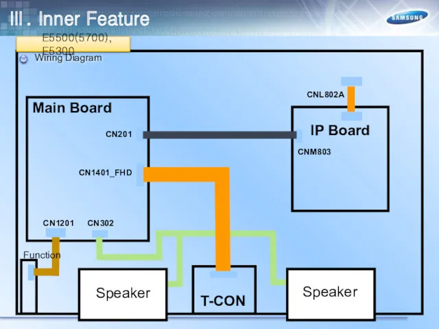
Wiring Diagram
E5500(5700), E5300
Ⅲ. Inner Feature
Wiring Diagram
E5500(5700), E5300
Ⅲ. Inner Feature
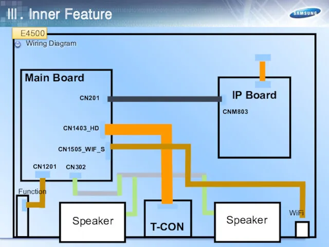
Wiring Diagram
WiFi
E4500
Ⅲ. Inner Feature
Wiring Diagram
WiFi
E4500
Ⅲ. Inner Feature
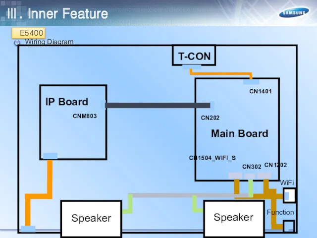
Wiring Diagram
E5400
T-CON
Main Board
IP Board
CN202
CN1401
CN1202
CN302
CNM803
Speaker
Speaker
WiFi
Function
CN1504_WIFI_S
Ⅲ. Inner Feature
Wiring Diagram
E5400
T-CON
Main Board
IP Board
CN202
CN1401
CN1202
CN302
CNM803
Speaker
Speaker
WiFi
Function
CN1504_WIFI_S
Ⅲ. Inner Feature
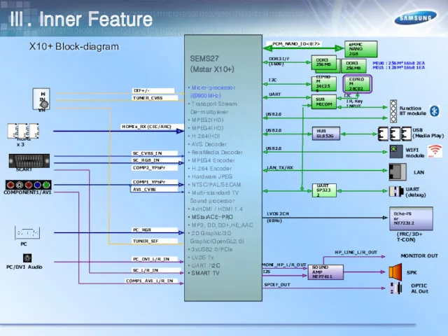
X10+ Block-diagram
PC_DVI_L/R_IN
AV1_CVBS
HDMIx_RX (CEC/ARC)
SEMS27
(Mstar X10+)
Micro-processor (@900MHz)
Transport Stream De-multiplexer
MPEG2(HD)
MPEG4(HD)
X10+ Block-diagram
PC_DVI_L/R_IN
AV1_CVBS
HDMIx_RX (CEC/ARC)
SEMS27
(Mstar X10+)
Micro-processor (@900MHz)
Transport Stream De-multiplexer
MPEG2(HD)
MPEG4(HD)
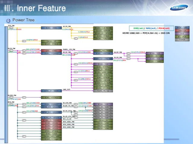
Power Tree
RMS(mA)/ MAX(mA) / PEAK(mA)
HDMI 1080/60i + PIP(H.264 ch) + OSD
Power Tree
RMS(mA)/ MAX(mA) / PEAK(mA)
HDMI 1080/60i + PIP(H.264 ch) + OSD
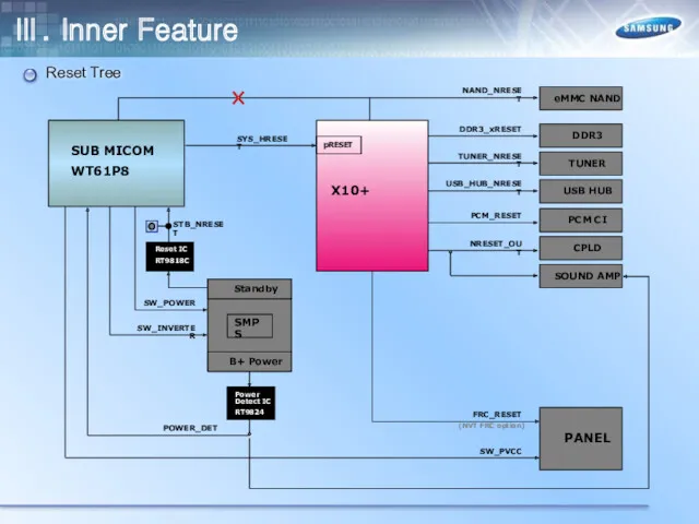
Reset Tree
STB_NRESET
SYS_HRESET
NRESET_OUT
TUNER_NRESET
SW_INVERTER
pRESET
USB_HUB_NRESET
USB HUB
PCM_RESET
SW_POWER
POWER_DET
TUNER
PCM CI
CPLD
SOUND AMP
DDR3
DDR3_xRESET
PANEL
FRC_RESET
SW_PVCC
eMMC NAND
NAND_NRESET
(NVT FRC option)
Ⅲ. Inner Feature
Reset Tree
STB_NRESET
SYS_HRESET
NRESET_OUT
TUNER_NRESET
SW_INVERTER
pRESET
USB_HUB_NRESET
USB HUB
PCM_RESET
SW_POWER
POWER_DET
TUNER
PCM CI
CPLD
SOUND AMP
DDR3
DDR3_xRESET
PANEL
FRC_RESET
SW_PVCC
eMMC NAND
NAND_NRESET
(NVT FRC option)
Ⅲ. Inner Feature
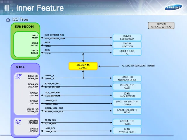
I2C Tree
X10+
GPIO56
GPIO55
SUB MICOM
IC301
NTP7412 (0x54)
DDCA_CK
DDCA_KA
GPIO108
GPIO109
DDCA_CK
DDCA_DA
MSCL
MSDA
DSCL2
DSDA2
DSCL1
DSDA1
SUB_EEPROM_SCL
SUB_EEPROM_SDA
MSCL
MSDA
AMP_SCL
AMP_SDA
DSCL
DSDA
DDCDx_CK
DDCDx_DA
HDMIx_SCL_DDC
HDMIx_SDA_DDC
CN601~3/IC601~3
HDMI
CN1401_FHD
PANEL
CN401 / IC401
PC
CN1201
FUNCTION
IC1203
SUB EEPROM
SWITCH IC
IC402
PC_DDC_EN (GPIO107)
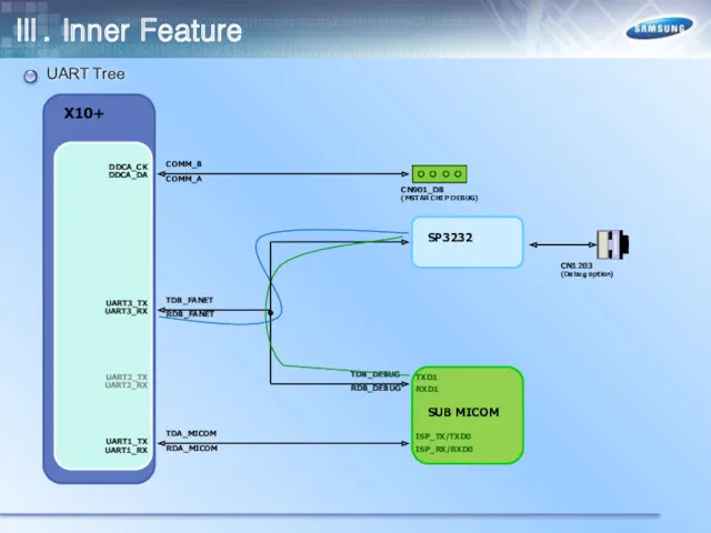
UART Tree
RDB_FANET
TDB_FANET
RDA_MICOM
TDA_MICOM
SUB MICOM
SP3232
RDB_DEBUG
TDB_DEBUG
CN1203
(Debug option)
ISP_TX/TXD0
ISP_RX/RXD0
TXD1
RXD1
COMM_A
COMM_B
CN901_DB
(MSTAR CHIP DEBUG)
Ⅲ. Inner Feature
UART Tree
RDB_FANET
TDB_FANET
RDA_MICOM
TDA_MICOM
SUB MICOM
SP3232
RDB_DEBUG
TDB_DEBUG
CN1203
(Debug option)
ISP_TX/TXD0
ISP_RX/RXD0
TXD1
RXD1
COMM_A
COMM_B
CN901_DB
(MSTAR CHIP DEBUG)
Ⅲ. Inner Feature
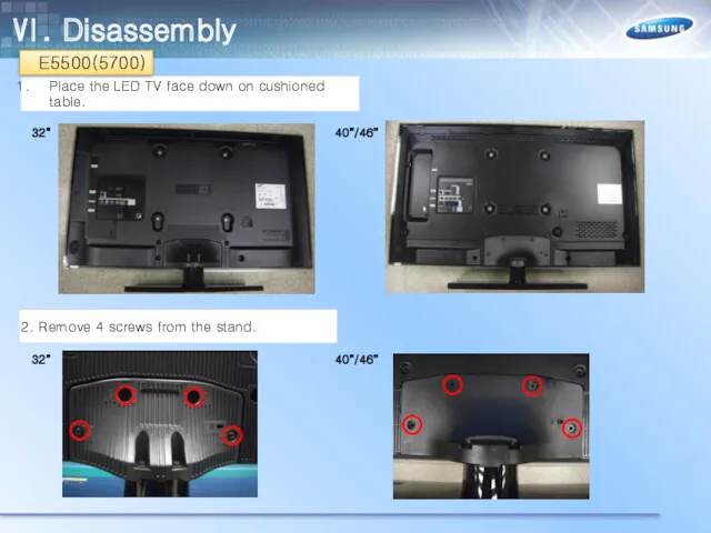
Ⅵ. Disassembly
Place the LED TV face down on cushioned table.
2.
Ⅵ. Disassembly
Place the LED TV face down on cushioned table.
2.
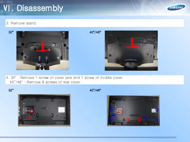
3. Remove stand.
4. 32" : Remove 1 screw of cover
3. Remove stand.
4. 32" : Remove 1 screw of cover
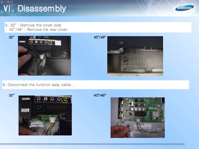
5. 32" : Remove the cover jack
40”/46" : Remove
5. 32" : Remove the cover jack
40”/46" : Remove
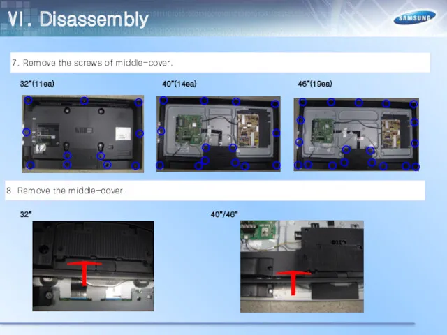
7. Remove the screws of middle-cover.
8. Remove the middle-cover.
32”(11ea)
40”(14ea)
46”(19ea)
32”
40”/46”
Ⅵ. Disassembly
7. Remove the screws of middle-cover.
8. Remove the middle-cover.
32”(11ea)
40”(14ea)
46”(19ea)
32”
40”/46”
Ⅵ. Disassembly
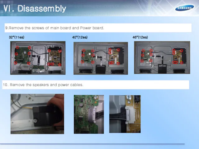
9.Remove the screws of main board and Power board.
10. Remove
9.Remove the screws of main board and Power board.
10. Remove
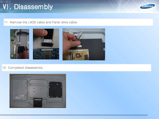
11. Remove the LVDS cable and Panel drive cable.
12. Completed
11. Remove the LVDS cable and Panel drive cable.
12. Completed
Place the LED TV face down on cushioned table.
2. Remove
Place the LED TV face down on cushioned table.
2. Remove
3. Remove stand.
4. 32“/40” : Remove 1 screw of cover
3. Remove stand.
4. 32“/40” : Remove 1 screw of cover
5. 32“/40” : Remove the cover jack
46" : Remove
5. 32“/40” : Remove the cover jack
46" : Remove
7. Remove the screws of middle-cover.
8. Remove the middle-cover.
32”(11ea)
40”(12ea)
46”(15ea)
32”/40”
46”
Ⅵ. Disassembly
7. Remove the screws of middle-cover.
8. Remove the middle-cover.
32”(11ea)
40”(12ea)
46”(15ea)
32”/40”
46”
Ⅵ. Disassembly
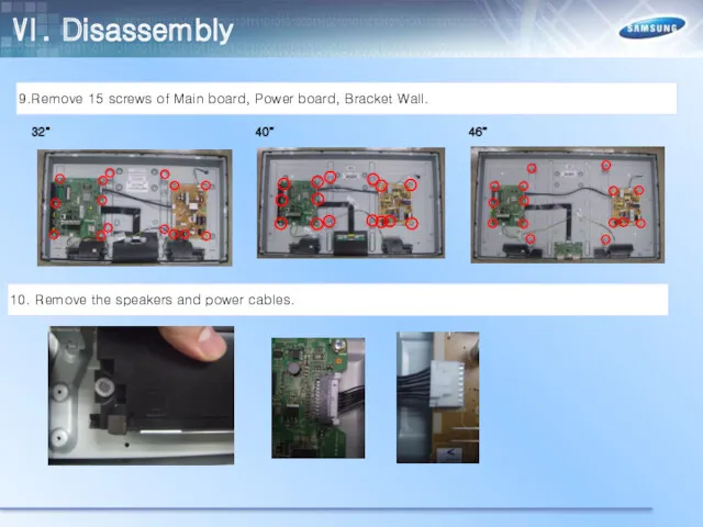
9.Remove 15 screws of Main board, Power board, Bracket Wall.
10.
9.Remove 15 screws of Main board, Power board, Bracket Wall.
10.
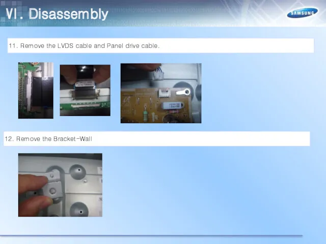
11. Remove the LVDS cable and Panel drive cable.
12. Remove
11. Remove the LVDS cable and Panel drive cable.
12. Remove
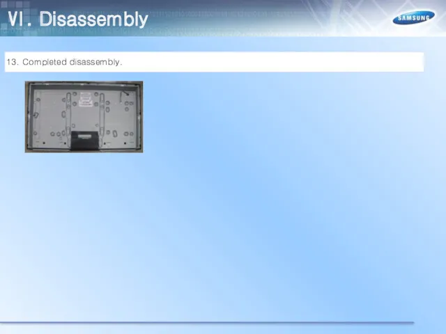
13. Completed disassembly.
Ⅵ. Disassembly
13. Completed disassembly.
Ⅵ. Disassembly
Place the LED TV face down on cushioned table.
2. Remove
Place the LED TV face down on cushioned table.
2. Remove
3. Remove stand.
4. Remove 11 screws of middle cover.
Ⅵ. Disassembly
3. Remove stand.
4. Remove 11 screws of middle cover.
Ⅵ. Disassembly
5. Remove the middle cover
6. Remove 11 screws of Main
5. Remove the middle cover
6. Remove 11 screws of Main
7. Disconnect the function assy cable.
8. Remove the speakers, power
7. Disconnect the function assy cable.
8. Remove the speakers, power
9. Remove the LVDS cable and Panel drive cable.
10. Remove
9. Remove the LVDS cable and Panel drive cable.
10. Remove
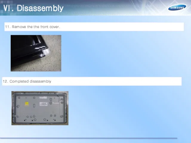
11. Remove the the front cover.
12. Completed disassembly
Ⅵ. Disassembly
11. Remove the the front cover.
12. Completed disassembly
Ⅵ. Disassembly
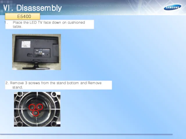
Place the LED TV face down on cushioned table.
2. Remove
Place the LED TV face down on cushioned table.
2. Remove
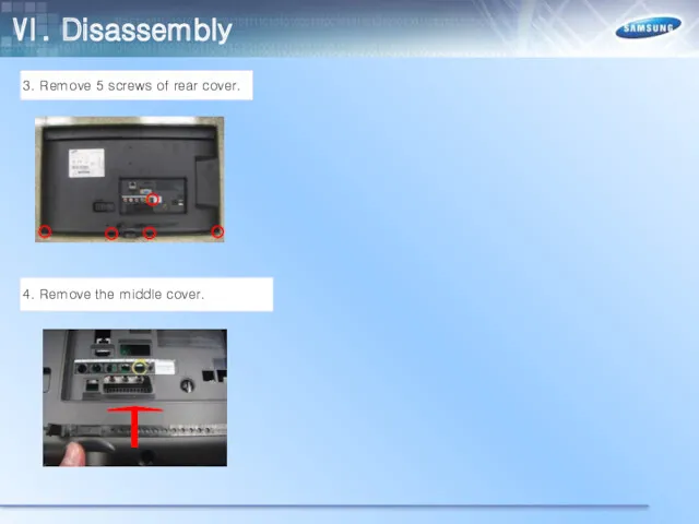
3. Remove 5 screws of rear cover.
4. Remove the middle
3. Remove 5 screws of rear cover.
4. Remove the middle
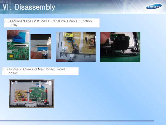
5. Disconnect the LVDS cable, Panel drive cable, function assy.
6.
5. Disconnect the LVDS cable, Panel drive cable, function assy.
6.
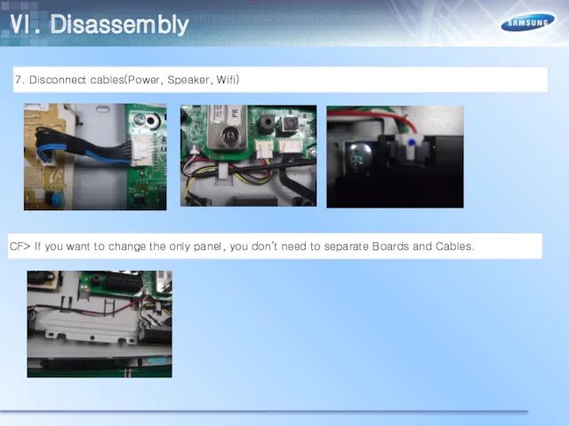
7. Disconnect cables(Power, Speaker, Wifi)
CF> If you want to change
7. Disconnect cables(Power, Speaker, Wifi)
CF> If you want to change
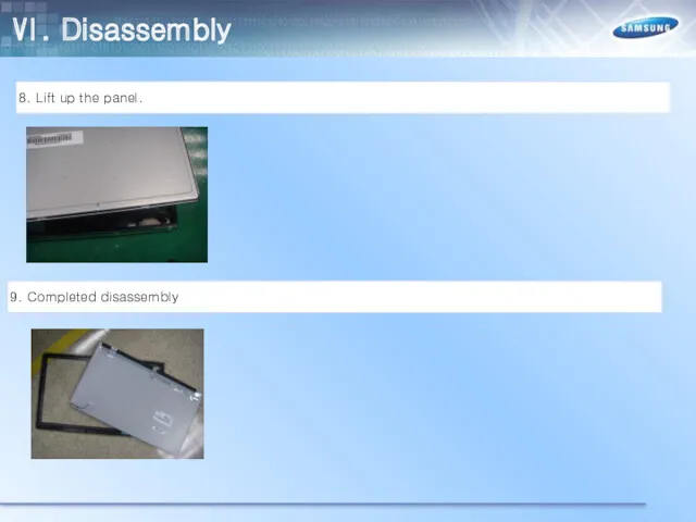
8. Lift up the panel.
9. Completed disassembly
Ⅵ. Disassembly
8. Lift up the panel.
9. Completed disassembly
Ⅵ. Disassembly
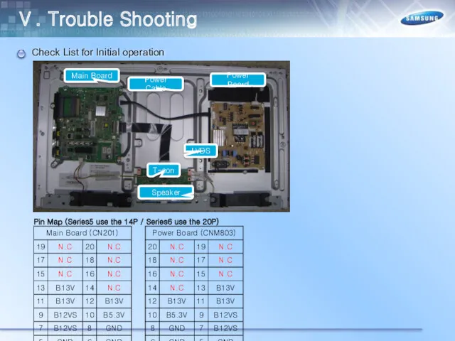
Check List for Initial operation
Main Board
Power Board
Power Cable
LVDS
Ⅴ. Trouble Shooting
T-con
Check List for Initial operation
Main Board
Power Board
Power Cable
LVDS
Ⅴ. Trouble Shooting
T-con
Ⅴ. Trouble Shooting
No power AND No Video
Model : UE**ES5500W***
UE**EH5300W***
Ⅴ. Trouble Shooting
No power AND No Video
Model : UE**ES5500W***
UE**EH5300W***
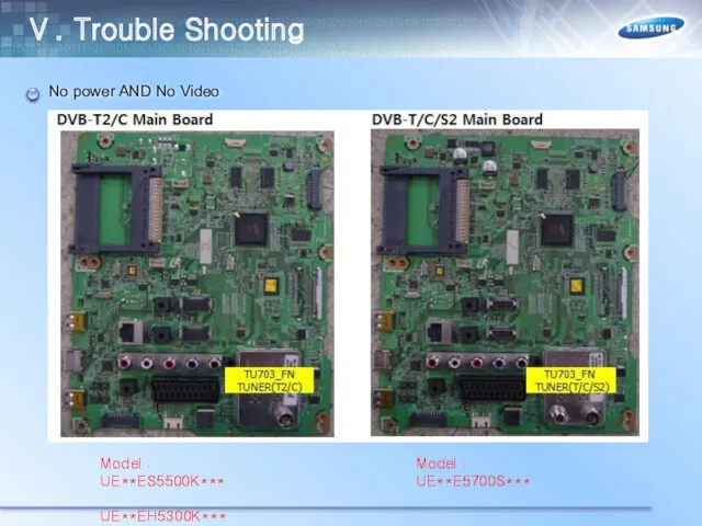
Ⅴ. Trouble Shooting
No power AND No Video
Model : UE**ES5500K***
UE**EH5300K***
Model :
Ⅴ. Trouble Shooting
No power AND No Video
Model : UE**ES5500K***
UE**EH5300K***
Model :
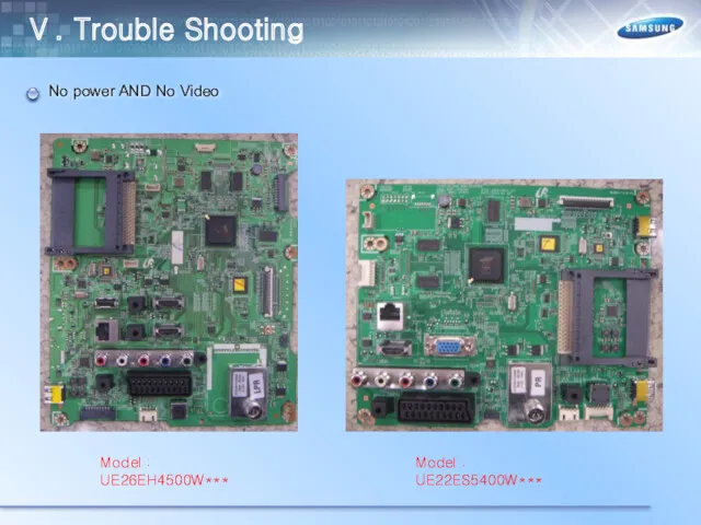
Ⅴ. Trouble Shooting
No power AND No Video
Model : UE26EH4500W***
Model : UE22ES5400W***
Ⅴ. Trouble Shooting
No power AND No Video
Model : UE26EH4500W***
Model : UE22ES5400W***
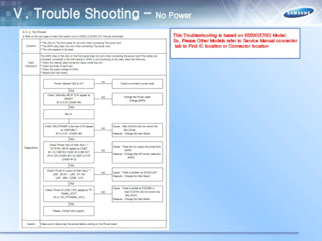
Ⅴ. Trouble Shooting – No Power
This Troubleshooting is based on E5500(5700)
Ⅴ. Trouble Shooting – No Power
This Troubleshooting is based on E5500(5700)
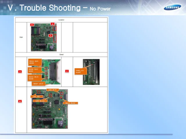
Ⅴ. Trouble Shooting – No Power
Ⅴ. Trouble Shooting – No Power
Ⅴ. Trouble Shooting – No Video (HDMI 1, 2, 3 -
Ⅴ. Trouble Shooting – No Video (HDMI 1, 2, 3 -
Ⅴ. Trouble Shooting – No Video (HDMI 1, 2, 3 -
Ⅴ. Trouble Shooting – No Video (HDMI 1, 2, 3 -
Ⅴ. Trouble Shooting – No Video (Tuner_CVBS)
Ⅴ. Trouble Shooting – No Video (Tuner_CVBS)
Ⅴ. Trouble Shooting – No Video (Tuner_CVBS)
Ⅴ. Trouble Shooting – No Video (Tuner_CVBS)
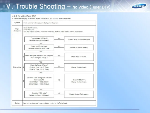
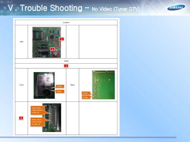
Ⅴ. Trouble Shooting – No Video (Tuner DTV)
Ⅴ. Trouble Shooting – No Video (Tuner DTV)
Ⅴ. Trouble Shooting – No Video (Tuner DTV)
Ⅴ. Trouble Shooting – No Video (Tuner DTV)
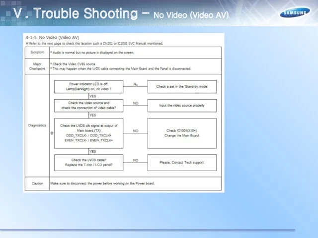
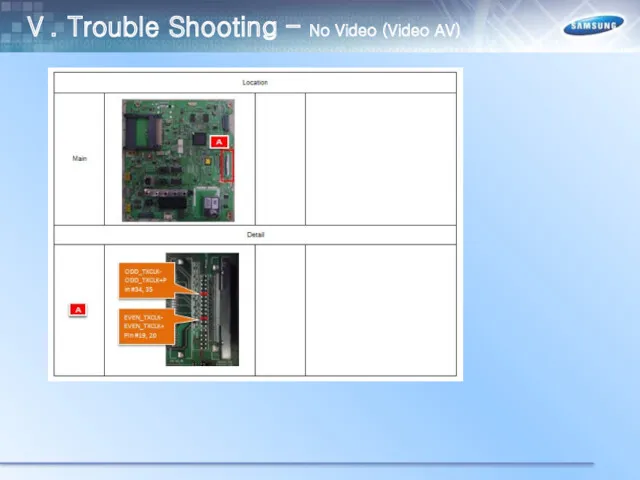
Ⅴ. Trouble Shooting – No Video (Video AV)
Ⅴ. Trouble Shooting – No Video (Video AV)
Ⅴ. Trouble Shooting – No Video (Video AV)
Ⅴ. Trouble Shooting – No Video (Video AV)
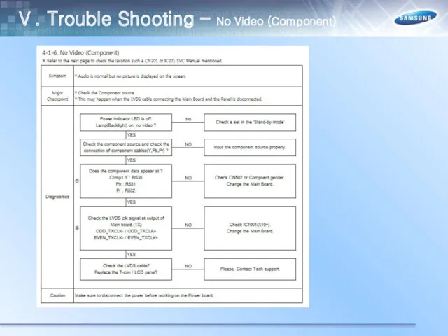
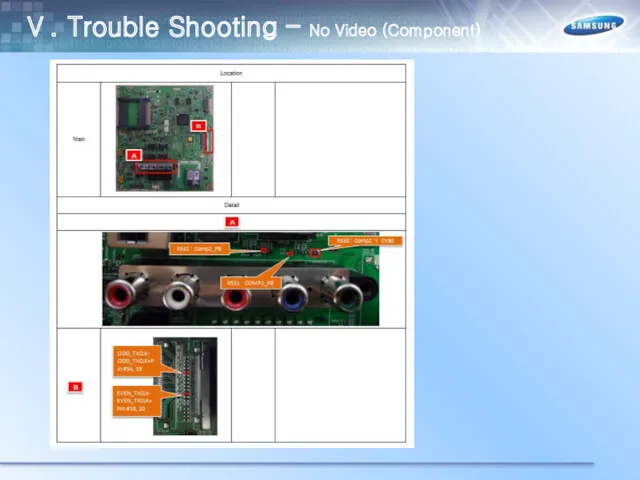
Ⅴ. Trouble Shooting – No Video (Component)
Ⅴ. Trouble Shooting – No Video (Component)
Ⅴ. Trouble Shooting – No Video (Component)
Ⅴ. Trouble Shooting – No Video (Component)
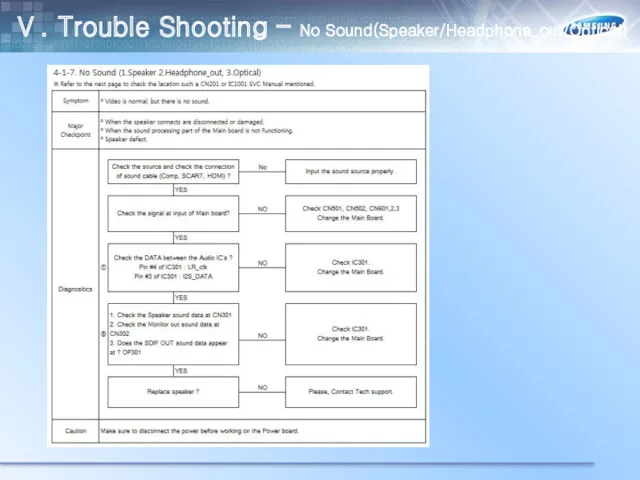
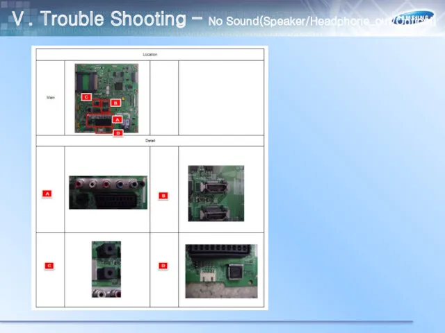
Ⅴ. Trouble Shooting – No Sound(Speaker/Headphone_out/Optical)
Ⅴ. Trouble Shooting – No Sound(Speaker/Headphone_out/Optical)
Ⅴ. Trouble Shooting – No Sound(Speaker/Headphone_out/Optical)
Ⅴ. Trouble Shooting – No Sound(Speaker/Headphone_out/Optical)
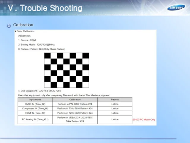
Ⅴ. Trouble Shooting
Calibration
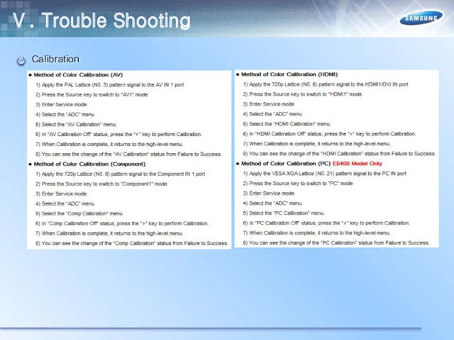
Ⅴ. Trouble Shooting
Calibration
Ⅴ. Trouble Shooting
Calibration
Ⅴ. Trouble Shooting
Calibration
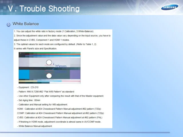
Ⅴ. Trouble Shooting
White Balance
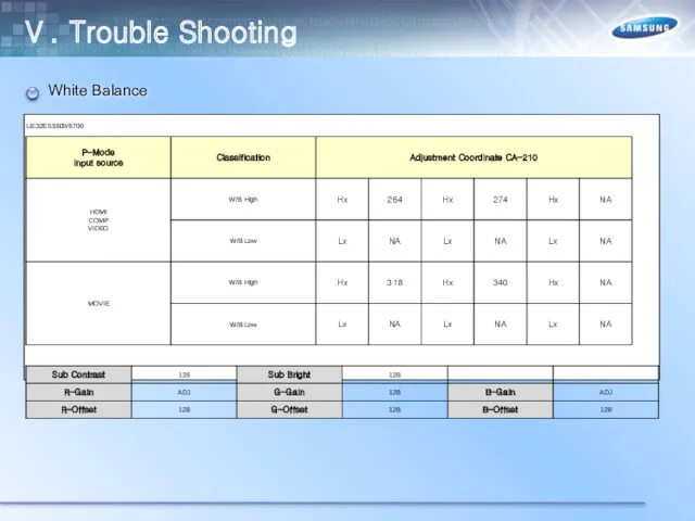
Ⅴ. Trouble Shooting
White Balance
Ⅴ. Trouble Shooting
White Balance
Ⅴ. Trouble Shooting
White Balance

Ⅴ. Trouble Shooting
White Balance
Ⅴ. Trouble Shooting
White Balance

Ⅵ. Trouble Shooting
White Balance
Ⅵ. Trouble Shooting
White Balance

Ⅵ. Trouble Shooting
White Balance
Ⅵ. Trouble Shooting
White Balance

Ⅵ. Trouble Shooting
White Balance
Ⅵ. Trouble Shooting
White Balance

Ⅴ. Trouble Shooting
White Balance
Ⅴ. Trouble Shooting
White Balance

White Balance
Ⅴ. Trouble Shooting
White Balance
Ⅴ. Trouble Shooting
White Balance
Ⅴ. Trouble Shooting
White Balance
Ⅴ. Trouble Shooting
How to upgrade the SW version
Ⅴ. Trouble Shooting
How to upgrade the SW version
Ⅴ. Trouble Shooting
How to upgrade the SW version
Ⅴ. Trouble Shooting
How to upgrade the SW version
Ⅴ. Trouble Shooting
How to Upgade Main SW and Micom
Ⅴ. Trouble Shooting
How to Upgade Main SW and Micom
Ⅴ. Trouble Shooting
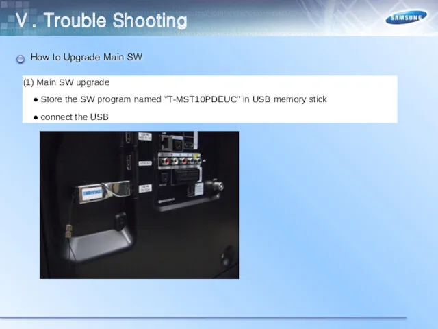
How to Upgrade Main SW
Ⅴ. Trouble Shooting
How to Upgrade Main SW
Ⅴ. Trouble Shooting
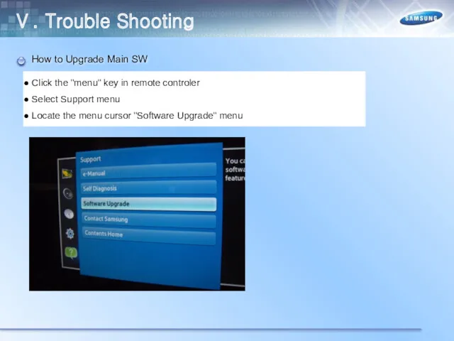
How to Upgrade Main SW
Ⅴ. Trouble Shooting
How to Upgrade Main SW
Ⅴ. Trouble Shooting
How to Upgrade Main SW
Ⅴ. Trouble Shooting
How to Upgrade Main SW
Ⅴ. Trouble Shooting
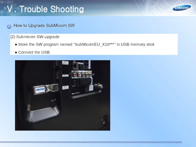
How to Upgrade SubMicom SW
Ⅴ. Trouble Shooting
How to Upgrade SubMicom SW
Ⅴ. Trouble Shooting
How to Upgrade SubMicom SW
Ⅴ. Trouble Shooting
How to Upgrade SubMicom SW
Ⅴ. Trouble Shooting
How to Upgrade SubMicom SW
Ⅵ. 12Year New Smart TV
Ⅴ. Trouble Shooting
How to Upgrade SubMicom SW
Ⅵ. 12Year New Smart TV
Ⅴ. Trouble Shooting
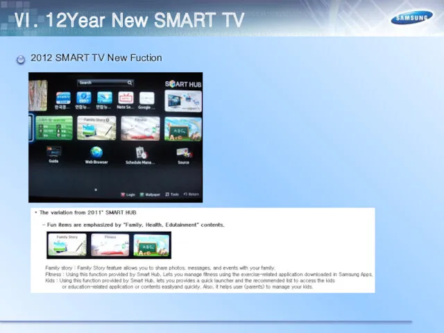
2012 SMART TV New Fuction
Ⅵ. 12Year New SMART TV
2012 SMART TV New Fuction
Ⅵ. 12Year New SMART TV
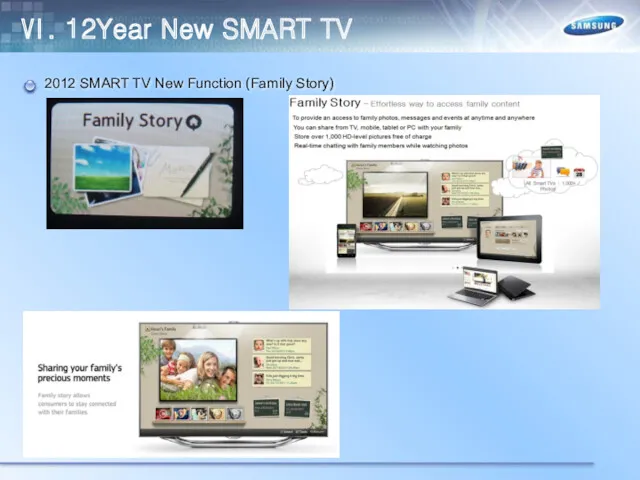
2012 SMART TV New Function (Family Story)
Ⅵ. 12Year New SMART TV
2012 SMART TV New Function (Family Story)
Ⅵ. 12Year New SMART TV
2012 SMART TV New Function (Family Story)
Ⅵ. 12Year New SMART TV
2012 SMART TV New Function (Family Story)
Ⅵ. 12Year New SMART TV
2012 SMART TV New Function (Family Story)
Ⅵ. 12Year New SMART TV
2012 SMART TV New Function (Family Story)
Ⅵ. 12Year New SMART TV
2012 SMART TV New Fuction (Family Story)
Ⅵ. 12Year New SMART TV
2012 SMART TV New Fuction (Family Story)
Ⅵ. 12Year New SMART TV
2012 SMART TV New Function (Family Story)
Ⅵ. 12Year New SMART TV
2012 SMART TV New Function (Family Story)
Ⅵ. 12Year New SMART TV
2012 SMART TV New Function (Family Story)
Ⅵ. 12Year New SMART TV
2012 SMART TV New Function (Family Story)
Ⅵ. 12Year New SMART TV
2012 SMART TV New Function (Family Story)
Ⅵ. 12Year New SMART TV
2012 SMART TV New Function (Family Story)
Ⅵ. 12Year New SMART TV
2012 SMART TV New Function (Family Story)
Ⅵ. 12Year New SMART TV
2012 SMART TV New Function (Family Story)
Ⅵ. 12Year New SMART TV
2012 SMART TV New Function (Fitness)
Ⅵ. 12Year New SMART TV
2012 SMART TV New Function (Fitness)
Ⅵ. 12Year New SMART TV
2012 SMART TV New Function (Fitness)
Ⅵ. 12Year New SMART TV
2012 SMART TV New Function (Fitness)
Ⅵ. 12Year New SMART TV
2012 SMART TV New Function (Fitness)
Ⅵ. 12Year New SMART TV
2012 SMART TV New Function (Fitness)
Ⅵ. 12Year New SMART TV
2012 SMART TV New Function (Fitness)
Ⅵ. 12Year New SMART TV
2012 SMART TV New Function (Fitness)
Ⅵ. 12Year New SMART TV
2012 SMART TV New Function (Kids)
Ⅵ. 12Year New SMART TV
2012 SMART TV New Function (Kids)
Ⅵ. 12Year New SMART TV
2012 SMART TV New Function (Kids)
Ⅵ. 12Year New SMART TV
2012 SMART TV New Function (Kids)
Ⅵ. 12Year New SMART TV
2012 SMART TV New Function (Kids)
Ⅵ. 12Year New SMART TV
2012 SMART TV New Function (Kids)
Ⅵ. 12Year New SMART TV
 Spanning Tree Protocol (STP) ( протокол покрывающего дерева)
 Безопасные правила цифрового поведения. 9 класс
 Жадыны басқару
 Презентация Microsoft Office PowerPoint
 Массивы в Паскале. Одномерные массивы
 Проектирование Баз Данных. Основные понятия Теории Нормализации
 Составляющие государственной системы защиты информации
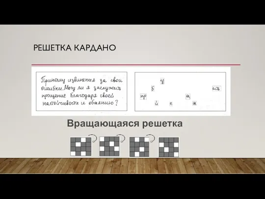 Криптография. Методы шифрования текста
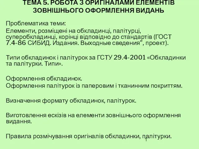 Робота з оригіналами елементів зовнішнього оформлення видань. (Тема 5)
 Модели и моделирование. Модели и их типы
 Atlas. Человекоподобный робот компании Boston Dynamics
 Создание 3D пазл для детей младшего возраста
 Выбор книг в библиотеке
 Основы информатики и программирования
 Решение заданий ЕГЭ по информатике №2 (А3) и №18 (А10)
 Использование пиксельных изображений в векторной графике и особенности работы с коллажами в Corel Draw
 Тема мастер класса: Роль текущего повторения для достижения результатов обучения.
 Афиши. Основы типографики для самых маленьких
 Основные направления развития искусственного интеллекта (лекция 2)
 Яким чином функціонує електронна пошта
 Комплексное решение для индустрии красоты на платформе 1С
 Мультимедиа технология
 Методология управления качеством проекта профессиональной системой управления проектами MS Project
 Информационная система по управлению складскими запасами предприятия
 Методическая инструкция. Создание таблиц со схемами для отчета по выполненным работам
 Автоматизация обучения, оценки и развития персонала. Программные продукты и решения компании WebSoft
 Информационные ресурсы БИБЛИОТЕКИ Университета для программы MBA Управление в здравоохранении
 Обзор поисковых систем