- Working with the node network

Содержание
- 2. Session content TerraLive survey results & conclusion: Many common problems are related to difficulties with working
- 3. TerraLive survey results What aspect of Terragen 2 do you think holds back beginners most? The
- 4. Sessions’ goals and methods Discuss the process of creating this scene: Create basic terrain Detail with
- 5. Stage 1 of 7 Adding a terrain in TG
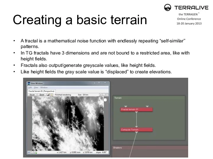
- 6. Creating a basic terrain A fractal is a mathematical noise function with endlessly repeating “self-similar” patterns.
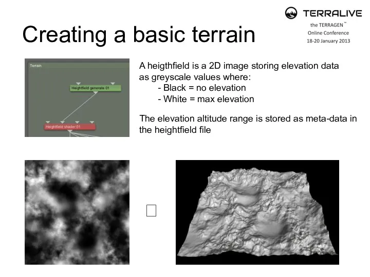
- 7. Creating a basic terrain A heigthfield is a 2D image storing elevation data as greyscale values
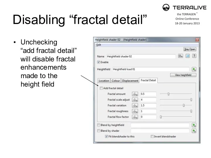
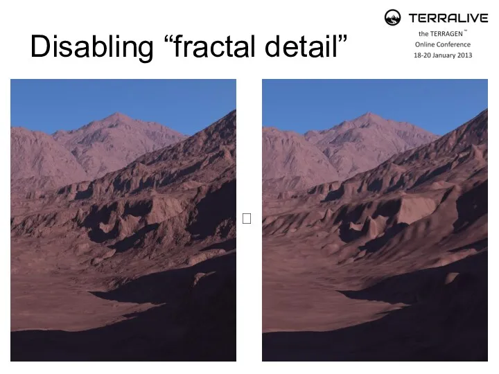
- 8. Disabling “fractal detail” Unchecking “add fractal detail” will disable fractal enhancements made to the height field
- 9. Disabling “fractal detail” ?
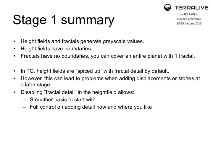
- 10. Stage 1 summary Height fields and fractals generate greyscale values. Height fields have boundaries Fractals have
- 11. Stage 2 of 7 Adding outcrops/overhangs by using “redirect shaders”
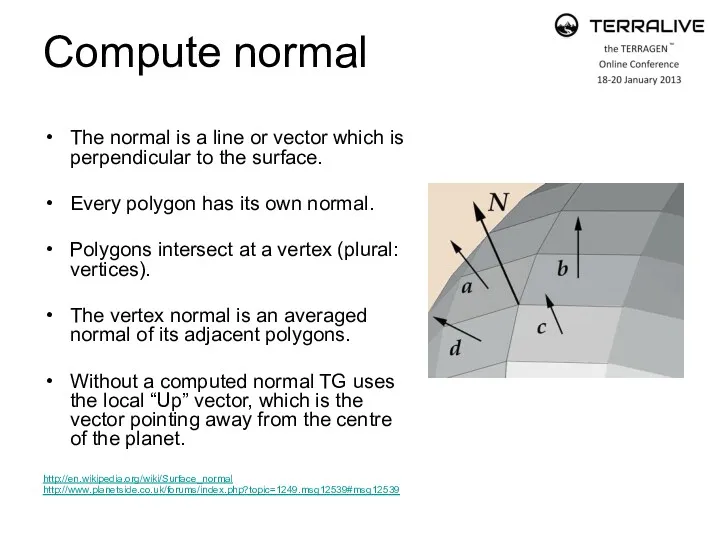
- 12. Compute normal The normal is a line or vector which is perpendicular to the surface. Every
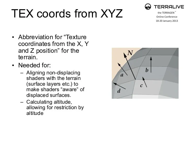
- 13. TEX coords from XYZ Abbreviation for “Texture coordinates from the X, Y and Z position” for
- 14. Compute Terrain Computes both the normals as well as the “texture coordinates”. Allows for: Altitude/slope restriction
- 15. Stage 2 result ?
- 16. Stage 2 summary Redirect shaders “trick” the displacement from a fractal to go into X, Y
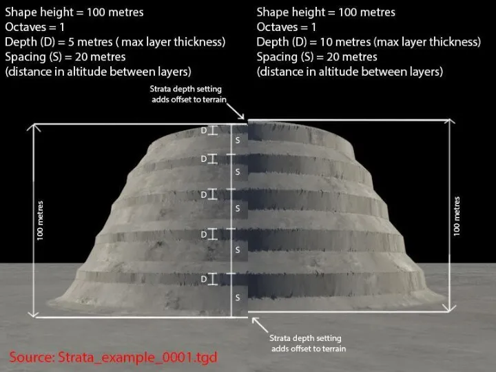
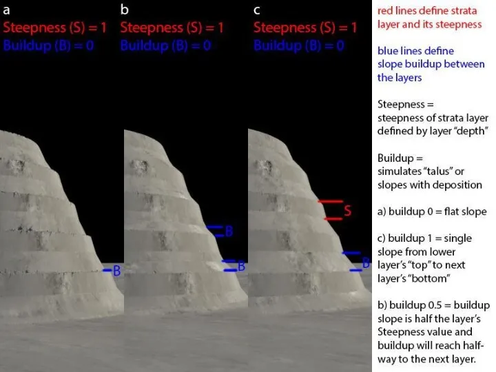
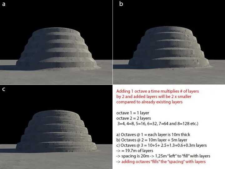
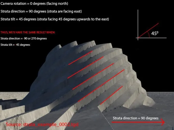
- 17. Stage 3 of 7 Adding strata by using the “Strata & Outcrops Shader”
- 18. Strata & Outcrops Shader Various settings for creating all kinds of effects… Let’s have a look!
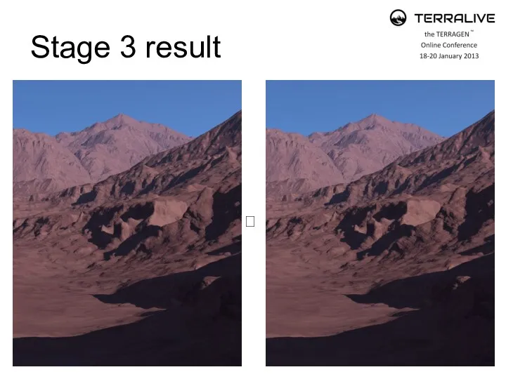
- 23. Stage 3 result ?
- 24. Stage 3 summary Strata & Outcrops Shader is very versatile Mixing strata to have them “intersect”
- 25. Stage 4 of 7 Adding cracks by using a “blue node mini network”
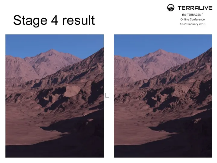
- 26. Stage 4 result ?
- 27. Stage 4 summary Blue nodes aren’t that scary, huh!? ☺ The “Get position…” nodes asks TG
- 28. Stage 5 of 7 Adding surface shaders
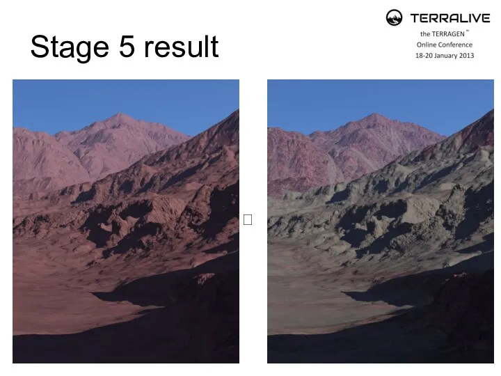
- 29. Stage 5 result ?
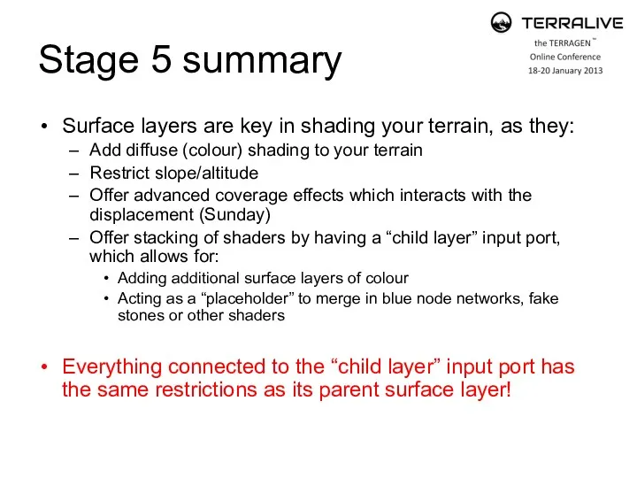
- 30. Stage 5 summary Surface layers are key in shading your terrain, as they: Add diffuse (colour)
- 31. Stage 6 of 7 Adding fake stones
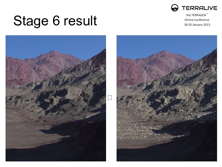
- 32. Stage 6 result ?
- 33. Stage 6 summary Fake stones can make/break your work Difficult to work with due to settings
- 34. Stage 7 of 7 Adding water
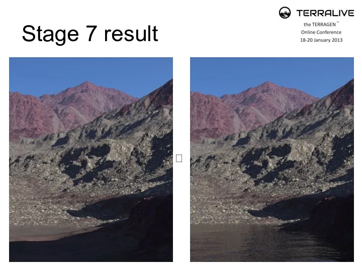
- 35. Stage 7 result ?
- 36. Stage 7 summary Lake object is a “disc” object, but you can use a plane object
- 38. Скачать презентацию
Session content
TerraLive survey results & conclusion:
Many common problems are related
Session content
TerraLive survey results & conclusion:
Many common problems are related
TerraLive survey results
What aspect of Terragen 2 do you think holds
TerraLive survey results
What aspect of Terragen 2 do you think holds
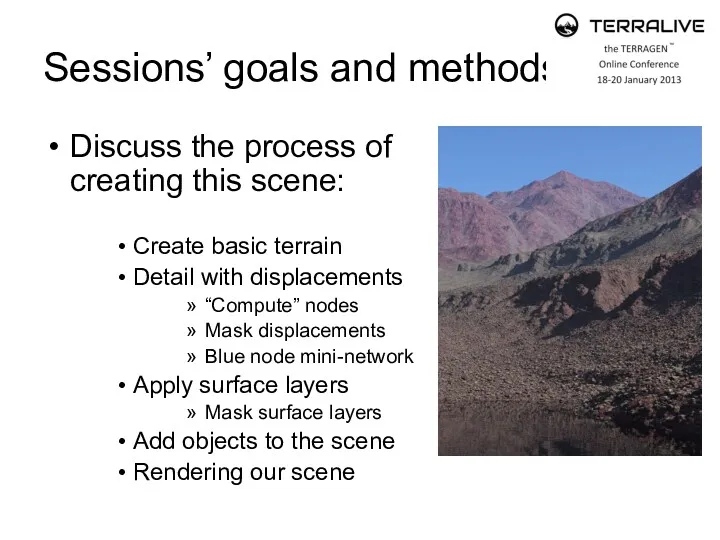
Sessions’ goals and methods
Discuss the process of creating this scene:
Create basic
Sessions’ goals and methods
Discuss the process of creating this scene:
Create basic
Stage 1 of 7
Adding a terrain in TG
Stage 1 of 7
Adding a terrain in TG
Creating a basic terrain
A fractal is a mathematical noise function with
Creating a basic terrain
A fractal is a mathematical noise function with
Creating a basic terrain
A heigthfield is a 2D image storing elevation
Creating a basic terrain
A heigthfield is a 2D image storing elevation
Disabling “fractal detail”
Unchecking
“add fractal detail”
will disable fractal
enhancements
made to the
height
Disabling “fractal detail”
Unchecking “add fractal detail” will disable fractal enhancements made to the height
Disabling “fractal detail”
?
Disabling “fractal detail”
?
Stage 1 summary
Height fields and fractals generate greyscale values.
Height fields have
Stage 1 summary
Height fields and fractals generate greyscale values.
Height fields have
Stage 2 of 7
Adding outcrops/overhangs by using “redirect shaders”
Stage 2 of 7
Adding outcrops/overhangs by using “redirect shaders”
Compute normal
The normal is a line or vector which is perpendicular
Compute normal
The normal is a line or vector which is perpendicular
TEX coords from XYZ
Abbreviation for “Texture coordinates from the X, Y
TEX coords from XYZ
Abbreviation for “Texture coordinates from the X, Y
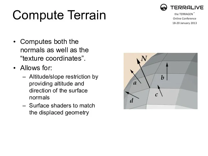
Compute Terrain
Computes both the normals as well as the “texture coordinates”.
Allows
Compute Terrain
Computes both the normals as well as the “texture coordinates”.
Allows
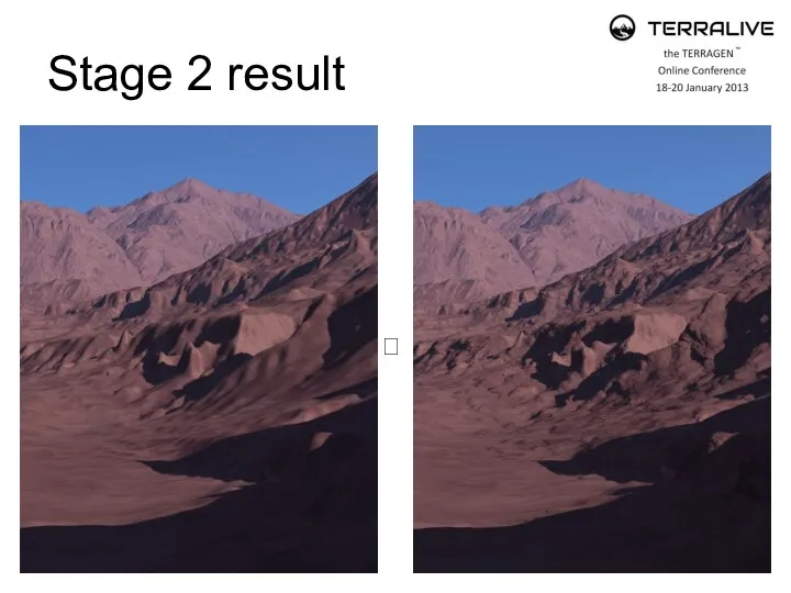
Stage 2 result
?
Stage 2 result
?
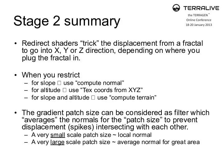
Stage 2 summary
Redirect shaders “trick” the displacement from a fractal to
Stage 2 summary
Redirect shaders “trick” the displacement from a fractal to

Stage 3 of 7
Adding strata by using the
“Strata & Outcrops
Stage 3 of 7
Adding strata by using the “Strata & Outcrops
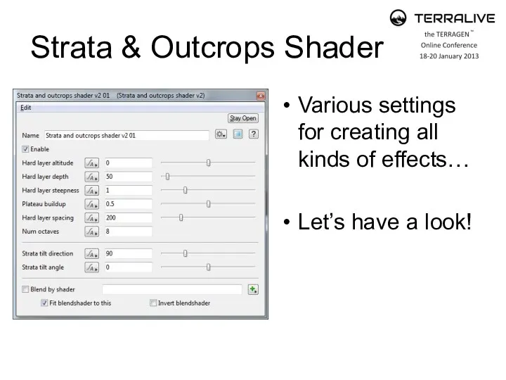
Strata & Outcrops Shader
Various settings for creating all kinds of effects…
Let’s
Strata & Outcrops Shader
Various settings for creating all kinds of effects…
Let’s
Stage 3 result
?
Stage 3 result
?
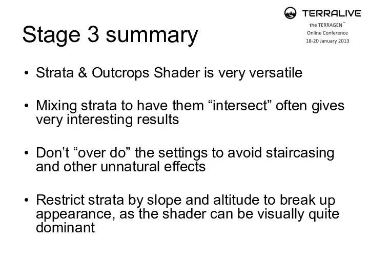
Stage 3 summary
Strata & Outcrops Shader is very versatile
Mixing strata to
Stage 3 summary
Strata & Outcrops Shader is very versatile
Mixing strata to
Stage 4 of 7
Adding cracks by using a
“blue node mini
Stage 4 of 7
Adding cracks by using a “blue node mini
Stage 4 result
?
Stage 4 result
?
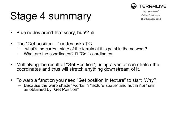
Stage 4 summary
Blue nodes aren’t that scary, huh!? ☺
The “Get position…”
Stage 4 summary
Blue nodes aren’t that scary, huh!? ☺
The “Get position…”
Stage 5 of 7
Adding surface shaders
Stage 5 of 7
Adding surface shaders
Stage 5 result
?
Stage 5 result
?
Stage 5 summary
Surface layers are key in shading your terrain, as
Stage 5 summary
Surface layers are key in shading your terrain, as
Stage 6 of 7
Adding fake stones
Stage 6 of 7
Adding fake stones
Stage 6 result
?
Stage 6 result
?
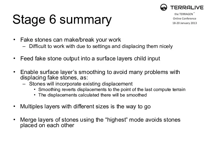
Stage 6 summary
Fake stones can make/break your work
Difficult to work with
Stage 6 summary
Fake stones can make/break your work
Difficult to work with
Stage 7 of 7
Adding water
Stage 7 of 7
Adding water
Stage 7 result
?
Stage 7 result
?
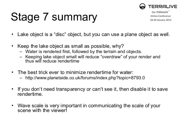
Stage 7 summary
Lake object is a “disc” object, but you can
Stage 7 summary
Lake object is a “disc” object, but you can
 Операторы переходов и циклов
 Великие открытия XX века в сфере информатики
 Характеристики відмінної вимоги. (Лекція 3.2)
 Назначение, структура и содержание процесса эксплуатации космических средств. Лекция №03
 Development in AB Suite
 Робот - помощник кулинара
 Десять трендов маркетинга здравоохранения
 Компьютерный турнир (внеклассное мероприятие)
 Телекоммуникационная система. Лекция 1
 История Интернета. События Internet
 Дистанционный урок по информатике 10 марта 2 класс
 Интернет-источники для поиска научной информации
 Программирование на Python. Урок 13. Игровое меню и события
 Пользовательский интерфейс информационных технологий. Стандарты пользовательского интерфейса информационных технологий
 Системы счисления. Представление информации в компьютере
 Персональный компьютер. Компьютер как унивесальное устройство для работы с информацией. Информатика. 7 класс
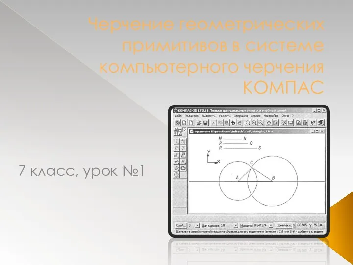 Черчение геометрических примитивов в системе компьютерного черчения КОМПАС
 Алгоритмы. Введение в программирование
 Урок в 8 классе по теме Компьютерные презентации
 Htc vive. Почему нужно покупать очки
 Как защититься от интернет-угроз
 Информационно-правовое обеспечение ГАРАНТ
 Wi-Fi. Обзор физического уровня
 Мало известные программы
 презентация по информатике для 2 класса Алфавит и кодирование информации
 Вимоги до оформлення презентації
 Презентация Отношения между понятиями
 12_Псевдоклассы. Псевдоэлементы