- Survey & Design Workshop

Содержание
- 2. Contents
- 3. TSSR output procedure
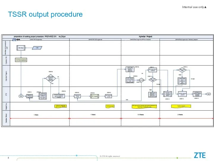
- 4. TSSR output procedure
- 5. Contents
- 6. Product Description – ZTE (-48V ) DC system 2000mm rack DC power solution scenario In case
- 7. Product Description – ZTE (-48V ) DC system 1600mm rack DC power solution scenario In case
- 8. Product Description – BBU B8200
- 9. DCPD6 Dimensions: 43.6 (h) x 482.6 (w) x 228 (d) (That means 1U space standard) Weight:
- 10. DCPD7 1,DC input interface 2,Switch for DC output for 10 paths(25A*10 paths) 3,Connector for DC output
- 11. Product Description – RRU (RRU types) ODCPD1 needed for R886X if 2*10mm DC cables used. R8863
- 12. R8881 Product Description – RRU R8863
- 13. Product Description – RRU R8861 R8862A
- 14. Product Description – Micro BTS B8908 (2G) B8908 BS8908 only used for sites which with following
- 15. Product Description – RRU RF cable RF G900 RRU (R8861 or R8881) In case of G900
- 16. Product Description – RRU RF cable RF D1800 RRU (R8862A) See blow RRU connection in case
- 17. Product Description – RRU RF cable RF U2100 RRU (R8861) See blow RRU connection in case
- 18. Product Description – RRU fiber cascading RRU fiber cascading There are 6 optic ports on BBU
- 19. Different types of Fiber for different RRU The type of BBU-RRU fiber for R888X and R886X
- 20. Site transmission Kiyvstar is responsed for upgrading the transmission to IP GE(E) .
- 21. AISG-U2100 R8861 RET Cell 1 Ant AISG RET Cell 2 Ant AISG RET Cell 3 Ant
- 22. AISG-U2100 R8863 RET Cell 1 Ant AISG RET Cell 2 Ant RET Cell 3 Ant R8863
- 23. Contents
- 24. Site overview
- 25. Site Scenarios-Site Equipment Principle
- 26. BBU and DCPD installation Scenario 1-In New/Existing 19” Rack BBU&DCPD to be installed on existing 19’Rack(Only
- 27. To be installed in New ZTE DC rack(Only for IBC sites) The solution only used in
- 28. 1 RRU fixing on pole kit-1 RRU need 1 set bracket (Pole diameter requirement: 40mm to
- 29. 2 RRU combined fixing on 1 pole kit - 2 RRU need 1 set bracket (Pole
- 30. 3 RRU combined fixing on 1 pole kit - 3 RRU need 1 set bracket (Pole
- 31. 4 RRU combined fixing on 1 pole kit - 4 RRU need 1 set bracket (Pole
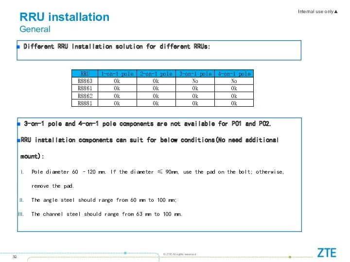
- 32. RRU installation General 3-on-1 pole and 4-on-1 pole components are not available for PO1 and PO2.
- 33. To be installed at the backside of antenna on the antenna pole Space behind the antenna
- 34. RRU installation components-Wall mount Wall mount fixing bracket kit---One RRU need 1 set bracket
- 35. RRU installation components-RRU gantry installation Indoor RRU gantry RRU installed on the Indoor RRU gantry This
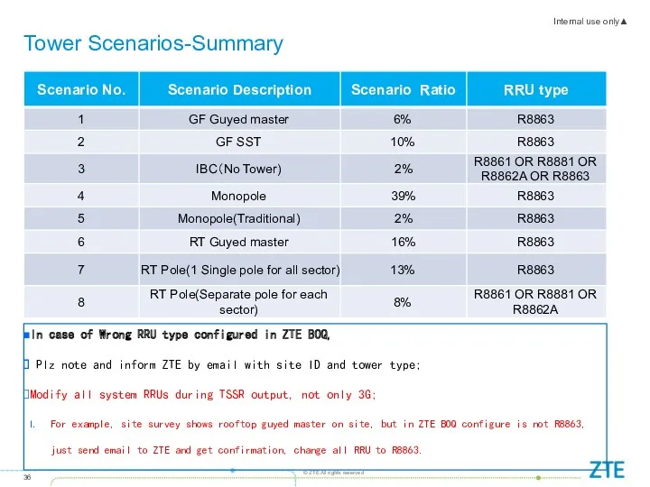
- 36. Tower Scenarios-Summary In case of Wrong RRU type configured in ZTE BOQ, Plz note and inform
- 37. Tower Scenarios
- 38. Tower Scenarios
- 39. Tower Scenarios Basic guidline for RRU installation For masters: U2100 R8863 to be installed on tower
- 40. "H" support structure-For RRU installation Can be used in following scenario Guyed master Monopole
- 41. “F" support structure-For RRU installation Can be used in following scenario Rooftop pole
- 42. Suggested RRU installation-Self support tower
- 43. Suggested RRU installation-Guyed master
- 44. Suggested RRU installation-Monopole
- 45. Suggested RRU installation- RT Pole(1 Single pole for all sector)
- 46. Suggested RRU installation-RT Pole(Separate pole for each sector)
- 47. Suggested RRU installation-RT Pole(Separate pole for each sector)
- 48. IBC sites solution scenario 1 Enough space for DC rack and RRU -48V DC rack +
- 49. IBC sites solution scenario 2(BS8908 Only can launch 2G) No space for DC rack and RRU
- 50. Antenna Scenarios Basic guidline for Antennas We should check all sector ports requirement for all system
- 51. Antenna Scenarios Filters G900 Filters will be reused if existed on site. Documents 305 sites ZTE
- 53. Скачать презентацию
Contents
Contents
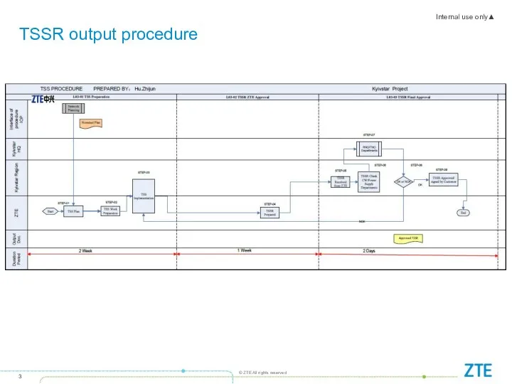
TSSR output procedure
TSSR output procedure
TSSR output procedure
TSSR output procedure
Contents
Contents
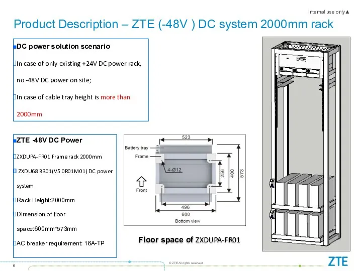
Product Description – ZTE (-48V ) DC system 2000mm rack
DC power
Product Description – ZTE (-48V ) DC system 2000mm rack
DC power
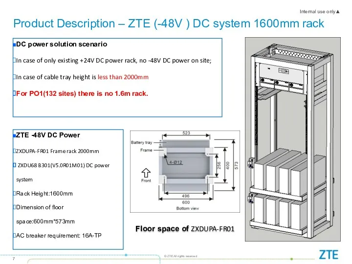
Product Description – ZTE (-48V ) DC system 1600mm rack
DC power
Product Description – ZTE (-48V ) DC system 1600mm rack
DC power
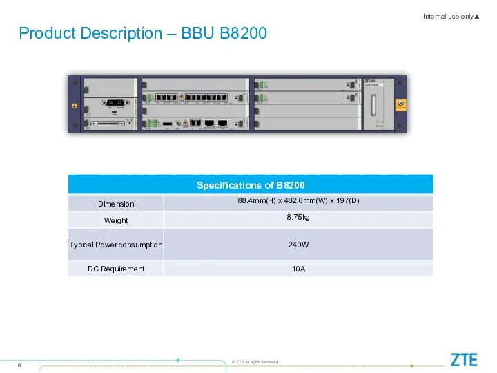
Product Description – BBU B8200
Product Description – BBU B8200
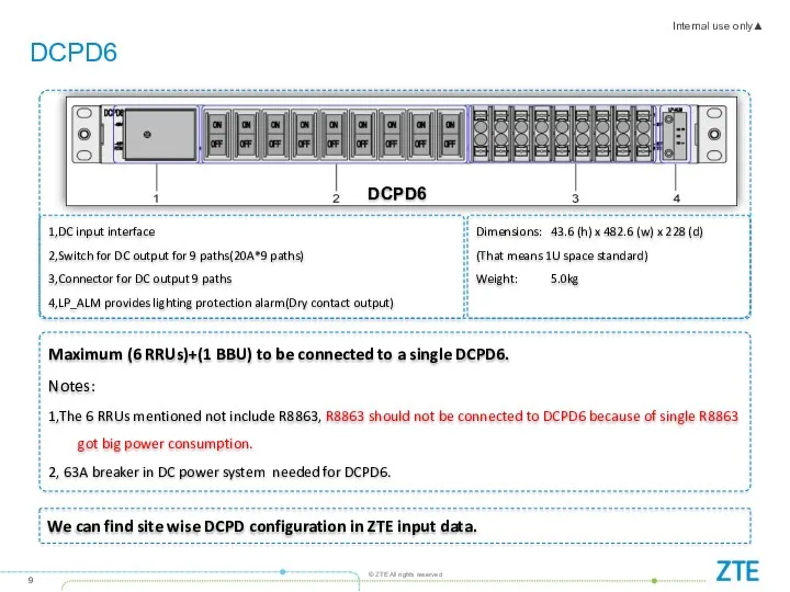
DCPD6
Dimensions: 43.6 (h) x 482.6 (w) x 228 (d)
(That means 1U
DCPD6
Dimensions: 43.6 (h) x 482.6 (w) x 228 (d)
(That means 1U
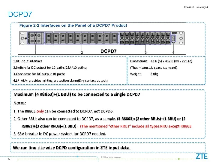
DCPD7
1,DC input interface
2,Switch for DC output for 10 paths(25A*10 paths)
3,Connector for
DCPD7
1,DC input interface
2,Switch for DC output for 10 paths(25A*10 paths)
3,Connector for
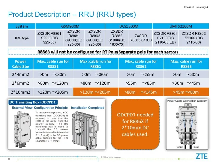
Product Description – RRU (RRU types)
ODCPD1 needed for R886X if 2*10mm
Product Description – RRU (RRU types)
ODCPD1 needed for R886X if 2*10mm
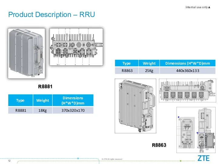
R8881
Product Description – RRU
R8863
R8881
Product Description – RRU
R8863
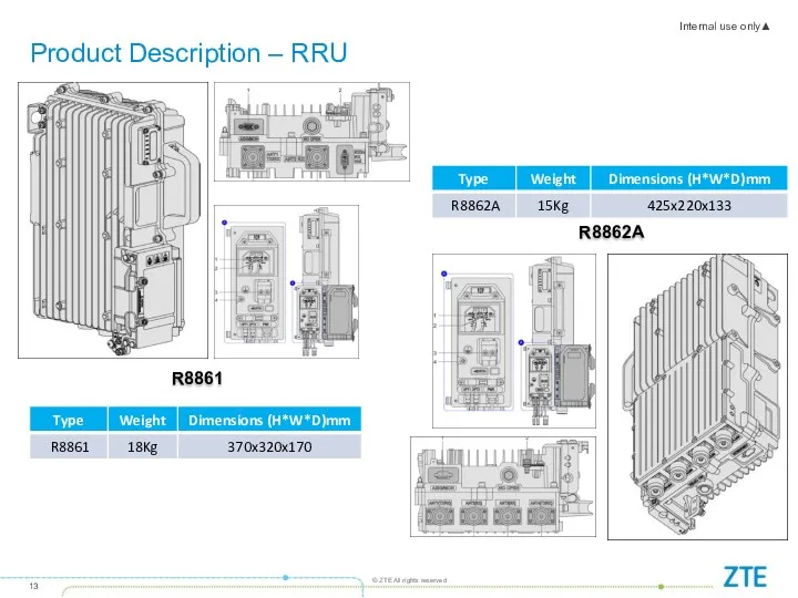
Product Description – RRU
R8861
R8862A
Product Description – RRU
R8861
R8862A
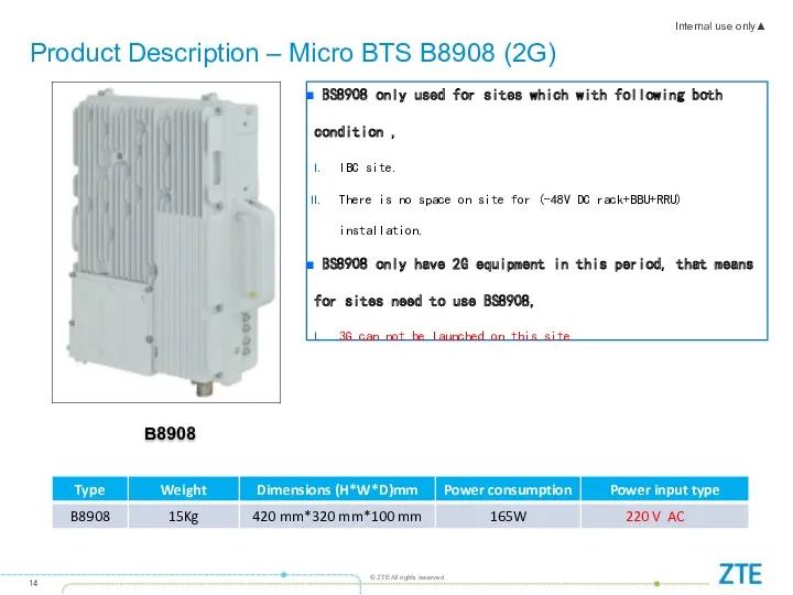
Product Description – Micro BTS B8908 (2G)
B8908
BS8908 only used
Product Description – Micro BTS B8908 (2G)
B8908
BS8908 only used
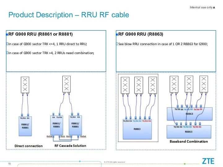
Product Description – RRU RF cable
RF G900 RRU (R8861 or R8881)
In
Product Description – RRU RF cable
RF G900 RRU (R8861 or R8881)
In
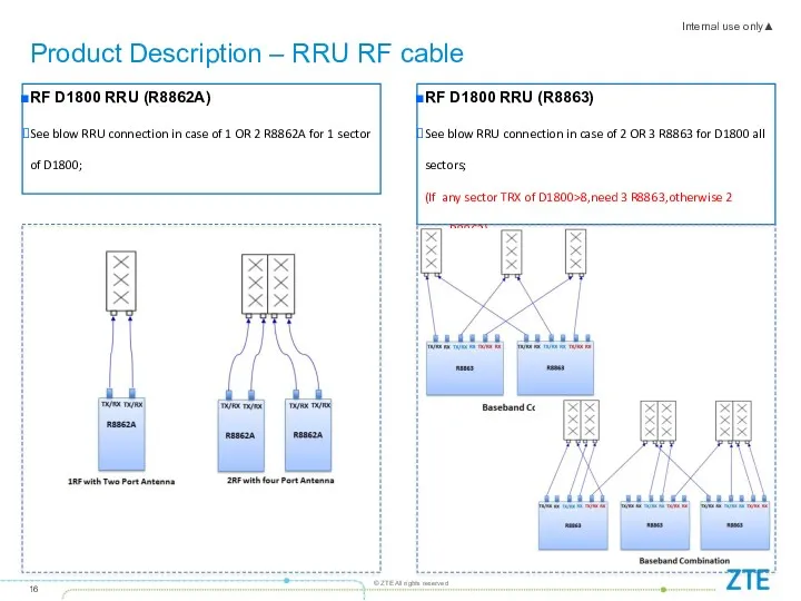
Product Description – RRU RF cable
RF D1800 RRU (R8862A)
See blow RRU
Product Description – RRU RF cable
RF D1800 RRU (R8862A)
See blow RRU
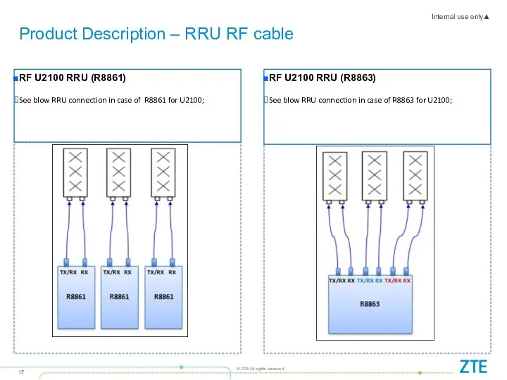
Product Description – RRU RF cable
RF U2100 RRU (R8861)
See blow RRU
Product Description – RRU RF cable
RF U2100 RRU (R8861)
See blow RRU
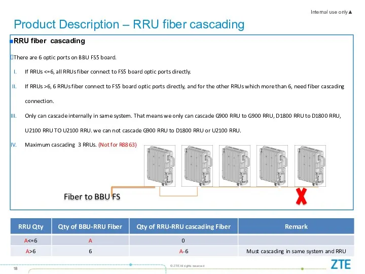
Product Description – RRU fiber cascading
RRU fiber cascading
There are 6 optic
Product Description – RRU fiber cascading
RRU fiber cascading
There are 6 optic
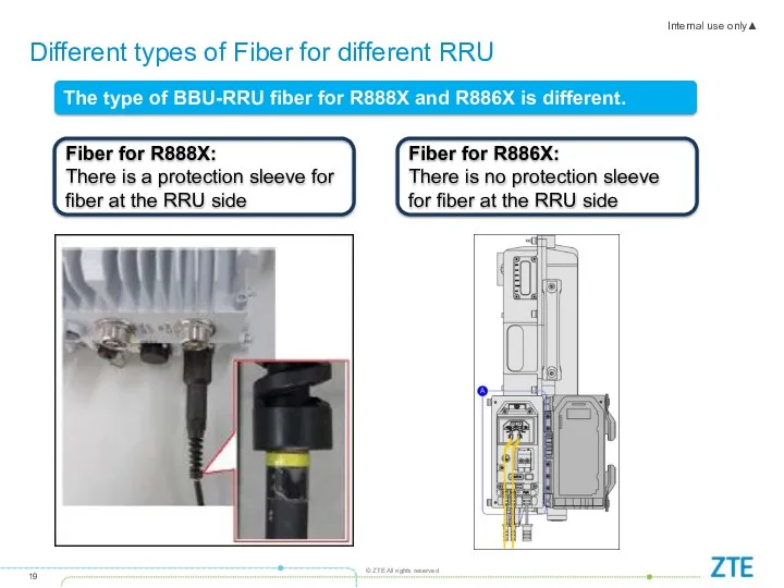
Different types of Fiber for different RRU
The type of BBU-RRU fiber
Different types of Fiber for different RRU
The type of BBU-RRU fiber
Site transmission
Kiyvstar is responsed for upgrading the transmission to IP GE(E)
Site transmission
Kiyvstar is responsed for upgrading the transmission to IP GE(E)
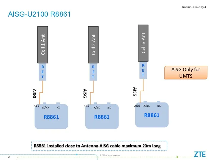
AISG-U2100 R8861
RET
Cell 1 Ant
AISG
RET
Cell 2 Ant
AISG
RET
Cell 3 Ant
AISG
R8861 installed close to
AISG-U2100 R8861
RET
Cell 1 Ant
AISG
RET
Cell 2 Ant
AISG
RET
Cell 3 Ant
AISG
R8861 installed close to
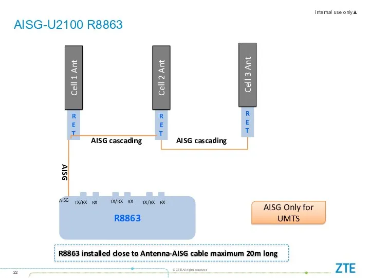
AISG-U2100 R8863
RET
Cell 1 Ant
AISG
RET
Cell 2 Ant
RET
Cell 3 Ant
R8863 installed close to
AISG-U2100 R8863
RET
Cell 1 Ant
AISG
RET
Cell 2 Ant
RET
Cell 3 Ant
R8863 installed close to
Contents
Contents
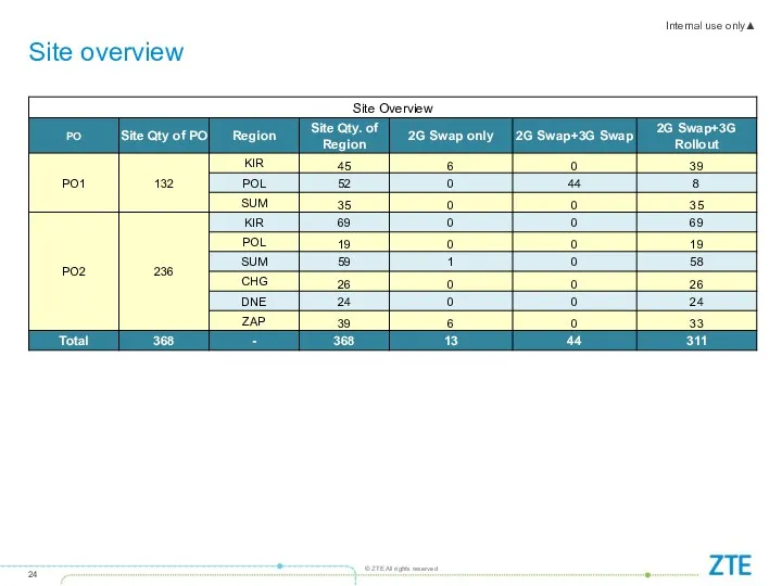
Site overview
Site overview
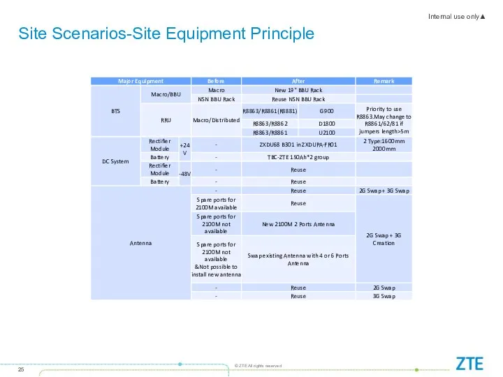
Site Scenarios-Site Equipment Principle
Site Scenarios-Site Equipment Principle
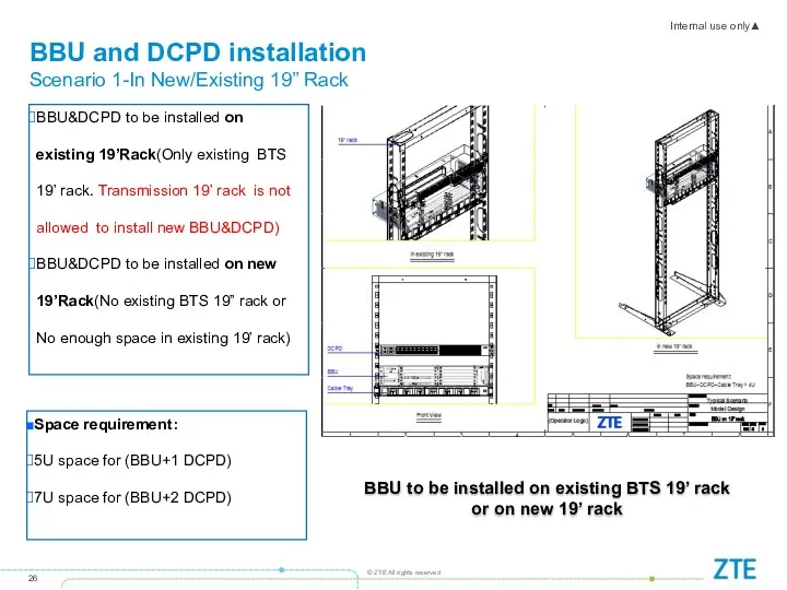
BBU and DCPD installation
Scenario 1-In New/Existing 19” Rack
BBU&DCPD to be installed
BBU and DCPD installation
Scenario 1-In New/Existing 19” Rack
BBU&DCPD to be installed
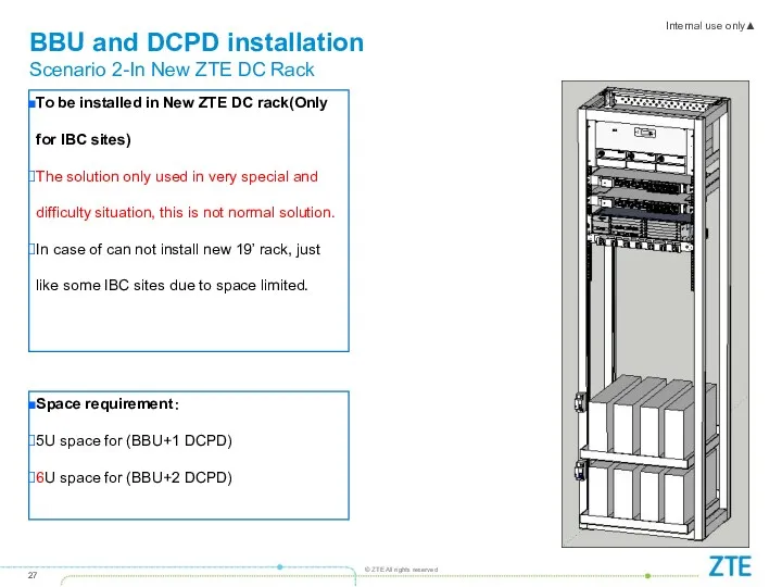
To be installed in New ZTE DC rack(Only for IBC sites)
The
To be installed in New ZTE DC rack(Only for IBC sites)
The
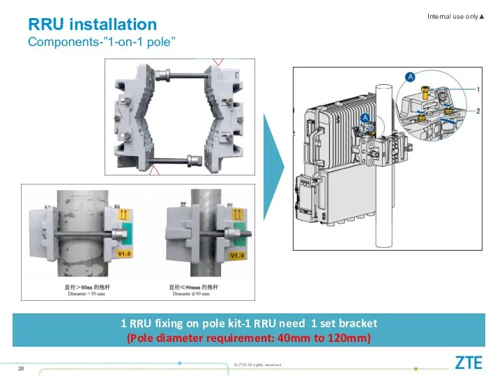
1 RRU fixing on pole kit-1 RRU need 1 set bracket
(Pole
1 RRU fixing on pole kit-1 RRU need 1 set bracket
(Pole
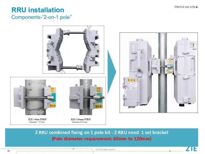
2 RRU combined fixing on 1 pole kit - 2 RRU
2 RRU combined fixing on 1 pole kit - 2 RRU
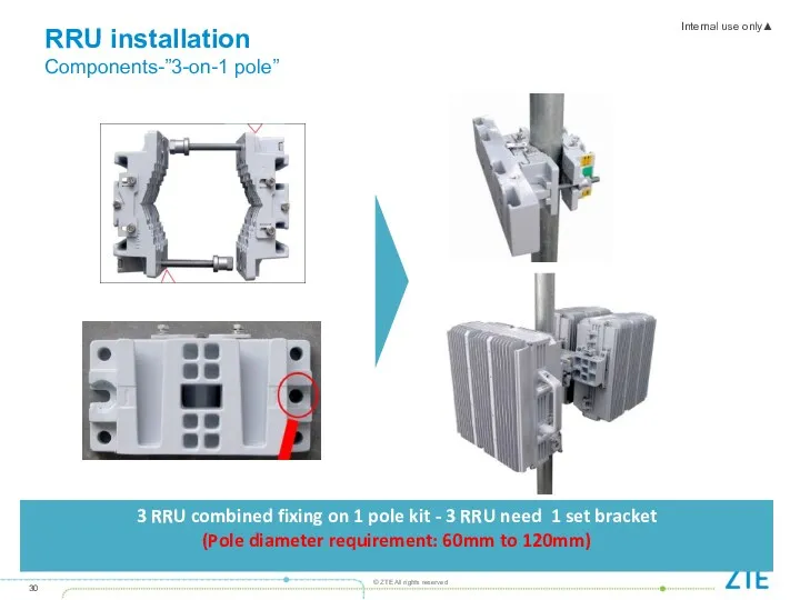
3 RRU combined fixing on 1 pole kit - 3 RRU
3 RRU combined fixing on 1 pole kit - 3 RRU
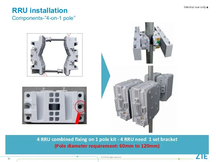
4 RRU combined fixing on 1 pole kit - 4 RRU
4 RRU combined fixing on 1 pole kit - 4 RRU
RRU installation
General
3-on-1 pole and 4-on-1 pole components are not available
RRU installation
General
3-on-1 pole and 4-on-1 pole components are not available
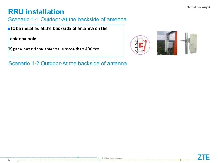
To be installed at the backside of antenna on the antenna
To be installed at the backside of antenna on the antenna
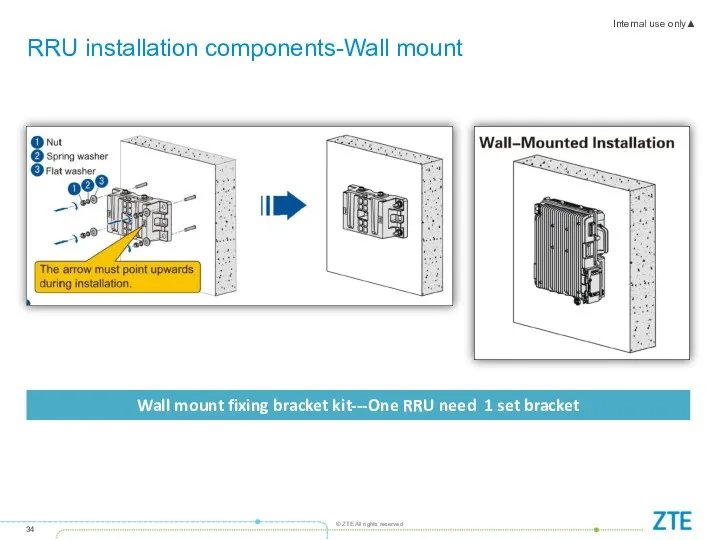
RRU installation components-Wall mount
Wall mount fixing bracket kit---One RRU need 1
RRU installation components-Wall mount
Wall mount fixing bracket kit---One RRU need 1
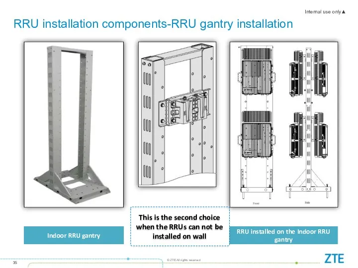
RRU installation components-RRU gantry installation
Indoor RRU gantry
RRU installed on the Indoor
RRU installation components-RRU gantry installation
Indoor RRU gantry
RRU installed on the Indoor
Tower Scenarios-Summary
In case of Wrong RRU type configured in ZTE BOQ,
Tower Scenarios-Summary
In case of Wrong RRU type configured in ZTE BOQ,
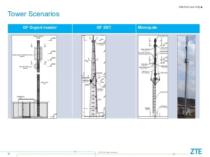
Tower Scenarios
Tower Scenarios
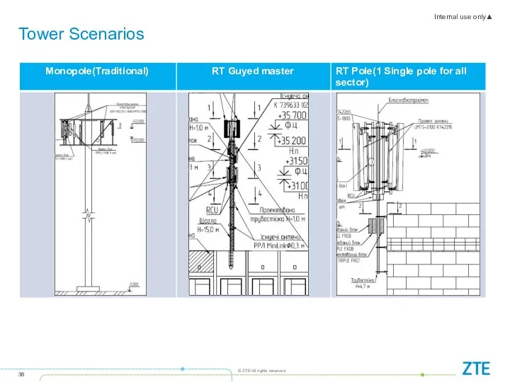
Tower Scenarios
Tower Scenarios
Tower Scenarios
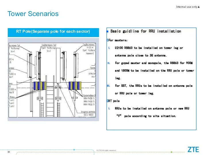
Basic guidline for RRU installation
For masters:
U2100 R8863 to be
Tower Scenarios
Basic guidline for RRU installation
For masters:
U2100 R8863 to be
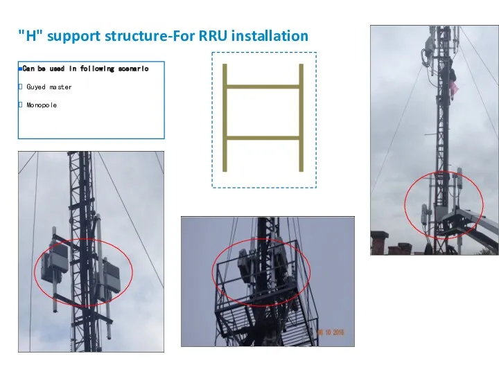
"H" support structure-For RRU installation
Can be used in following scenario
Guyed
"H" support structure-For RRU installation
Can be used in following scenario
Guyed
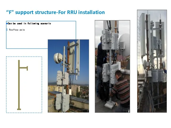
“F" support structure-For RRU installation
Can be used in following scenario
“F" support structure-For RRU installation
Can be used in following scenario
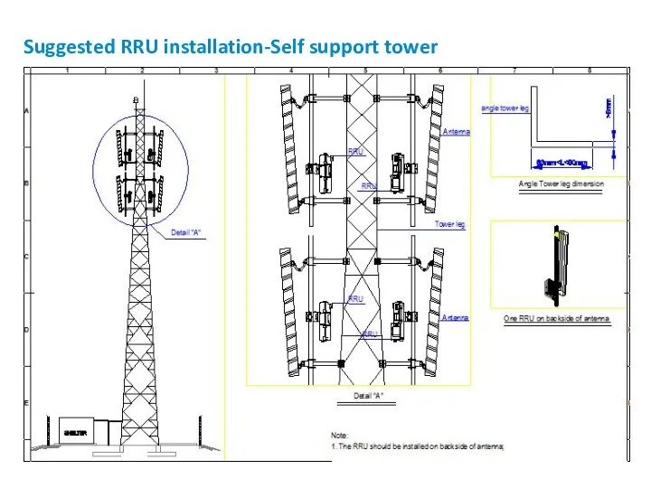
Suggested RRU installation-Self support tower
Suggested RRU installation-Self support tower
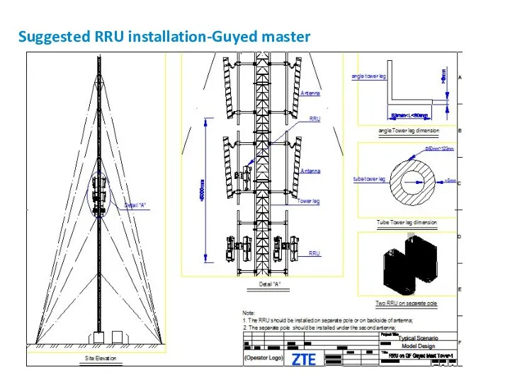
Suggested RRU installation-Guyed master
Suggested RRU installation-Guyed master
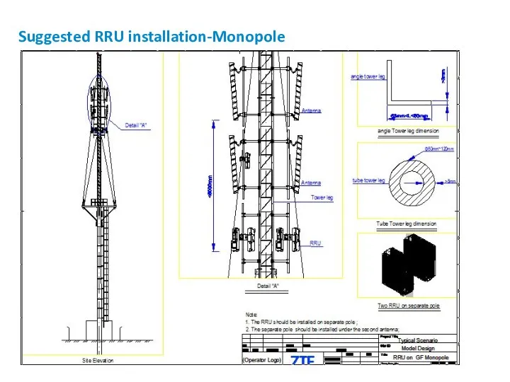
Suggested RRU installation-Monopole
Suggested RRU installation-Monopole
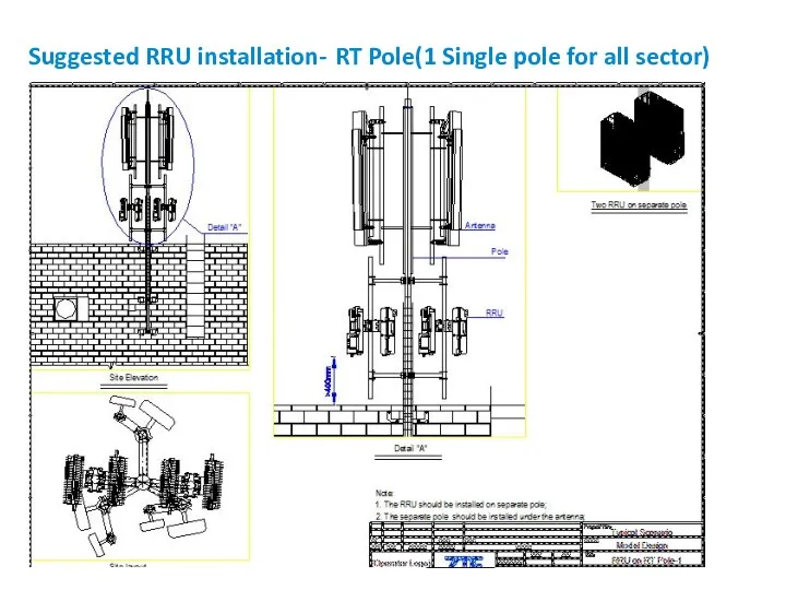
Suggested RRU installation- RT Pole(1 Single pole for all sector)
Suggested RRU installation- RT Pole(1 Single pole for all sector)
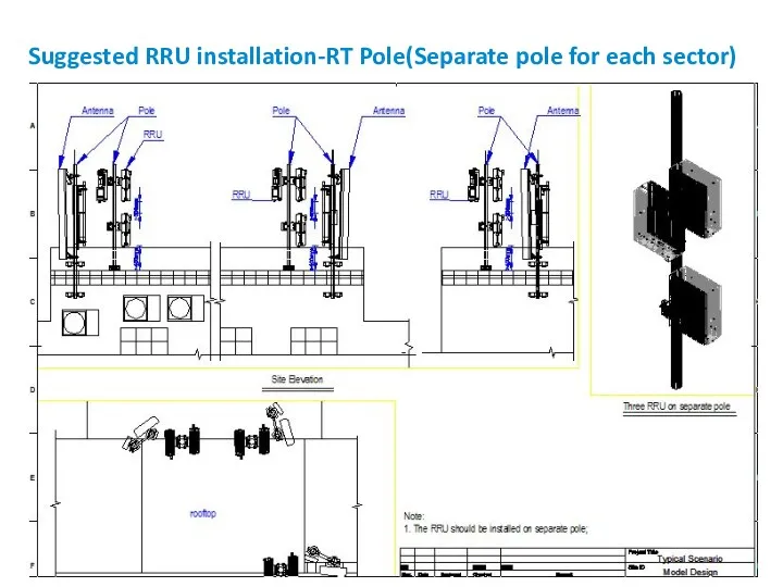
Suggested RRU installation-RT Pole(Separate pole for each sector)
Suggested RRU installation-RT Pole(Separate pole for each sector)
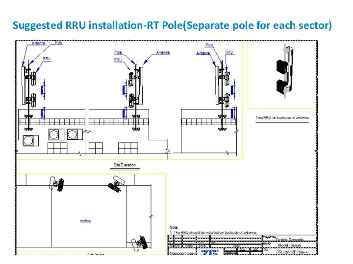
Suggested RRU installation-RT Pole(Separate pole for each sector)
Suggested RRU installation-RT Pole(Separate pole for each sector)
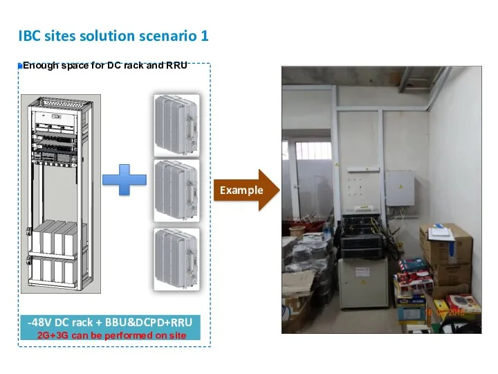
IBC sites solution scenario 1
Enough space for DC rack and RRU
-48V
IBC sites solution scenario 1
Enough space for DC rack and RRU
-48V
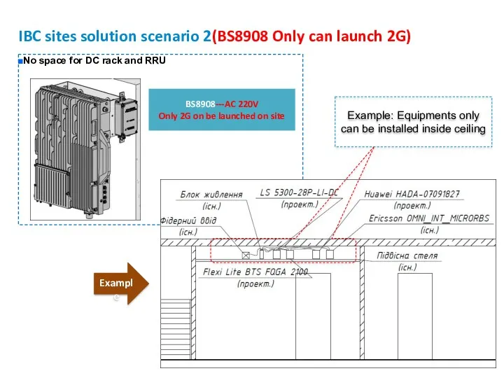
IBC sites solution scenario 2(BS8908 Only can launch 2G)
No space for
IBC sites solution scenario 2(BS8908 Only can launch 2G)
No space for
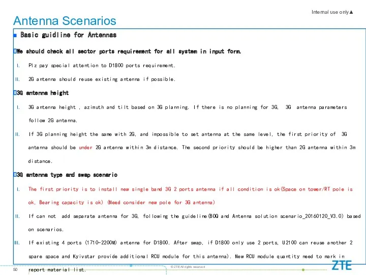
Antenna Scenarios
Basic guidline for Antennas
We should check all sector ports
Antenna Scenarios
Basic guidline for Antennas
We should check all sector ports
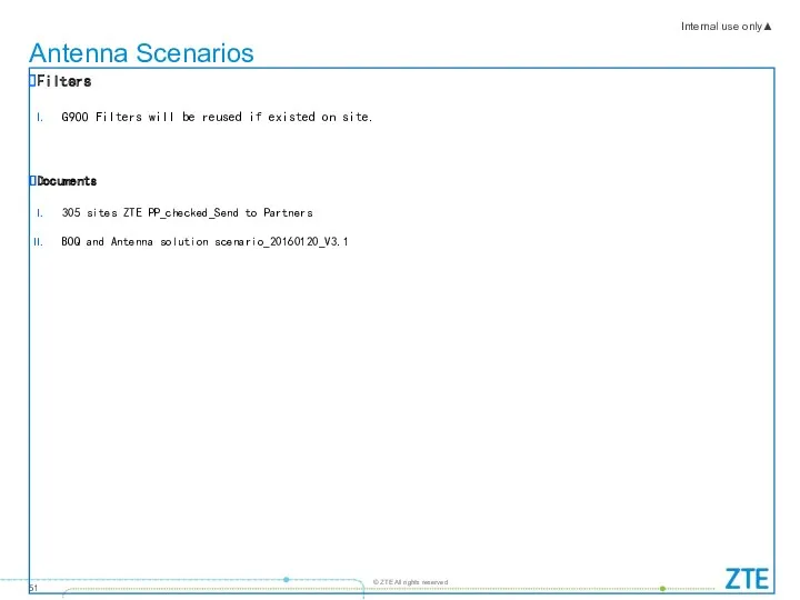
Antenna Scenarios
Filters
G900 Filters will be reused if existed on site.
Documents
305 sites
Antenna Scenarios
Filters
G900 Filters will be reused if existed on site.
Documents
305 sites
 Гостиница Шератон Палас
 Швейные машины Brother, A-серия(M2)
 Как привлечь онлайн-покупателя. Курс Онлайн партнер Оriflame. Модуль 5
 Группа компаний СМС автоматизация
 Физиотерапия. Что предлагает BTL для физиотерапии
 Примеры ячеек
 Продажи в онлайн
 Эклер клубничный. Лимитированная серия от Рошен
 Принципы продаж. Ошибки, техники, приемы
 Компания Дельта. Охрана недвижимости и имущества
 Оборудование PACK LINE
 Медиаплатформа ITV.BY. Предложение по сотрудничеству для сети магазинов 5 Элемент
 Mercedes-Benz G 65 AMG
 Целевая аудитория. Как создать портрет клиента
 Основы логики и программирования. Первое погружение в мир логики, алгоритмов и программирования
 Jamp Starter Aurora. Power Bank Aurora. Компактные аккумуляторные пуско-зарядные устройства (ПЗУ)
 Оборудование для приготовления и продажи напитков
 Локальный видеорегистратор
 Караоке без границ. Чемпионат России по караоке
 Смазочно-охлаждающие жидкости (СОЖ)
 Особенности В2В продаж
 Каталог Oriflame №01 2020
 Free Love маркетинг. Рутинный маркетинг
 Отчет о прохождении производственной практики (преддипломной). Специальность 38.02.04. Коммерция (по отраслям)
 Товарные знаки. НМПТ. Авторские права
 Декоративные краски и покрытия DEKOrus
 Стратегії розвитку бізнесу. Конкурентні стратегії
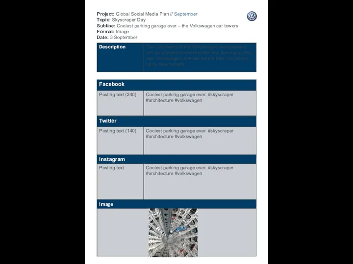 Project: Global Social Media Plan September Topic: Skyscraper Day Subline: Coolest parking garage ever-the Volkswagen car towers