- Basic Training

Содержание
- 2. SUM3D Workflow NEW JOB (.CAM) Import .STL Import Stock (Nesting) Calculation (NC FILE)
- 3. Interface Zoom & Viewing Toolbar Workflow Wizard (Primary Toolbar) Imported Strategy Information Equipment (Fixture / Stock
- 4. Changing the View with the Mouse ROTATION PANNING ZOOM + + (HOLD BOTH) (HOLD BOTH)
- 5. Display Toolbar Toggle Rendering of Surfaces Toggle Transparency of Imported Items Toggle Display of Curves (on/off)
- 6. Display Toolbar (Detailed) Toggle Rendering of Surfaces Toggle Transparency of Imported Items Sectioning / Slicing Toggle
- 7. Display Toolbar Show Tool Shaded Tool (Simulation) Redraw (Re-Render) Zoom & Panning Tools
- 8. Display Toolbar (Detailed) Distance between 2 points (Measurement) Show tool Show Machining side Show Back Face
- 9. Pre-Set Views Top view XY Front View - XZ Right View - YZ XZ Back View
- 10. Lower Information Bar Name of last .STL File Imported Name of Strategy Imported Material Stock /
- 11. Main Toolbar (Medium Interface)
- 12. Main Toolbar (Medium Interface) New Job Creation Import .STL file Select / Create Stock Create Program
- 13. Main Toolbar (High / Maximum) In the High / Maximum Level Interface of SUM3D, the user
- 14. Selection Toolbar Clear Selection List Add to Selection List Remove from Selection List Select by Color
- 15. Selection Toolbar (Detailed) Reset Selection List Add to Selection List Remove from Selection List Select All
- 16. Using the Mouse with the Selection Toolbar Selection End Selection
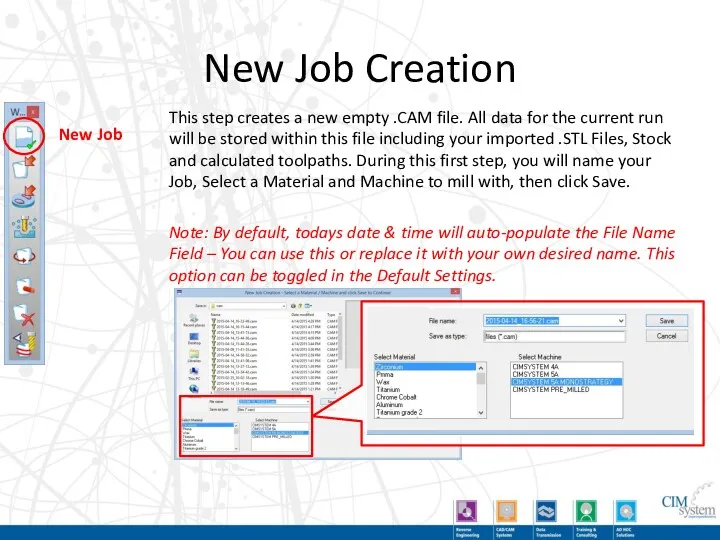
- 17. New Job Creation This step creates a new empty .CAM file. All data for the current
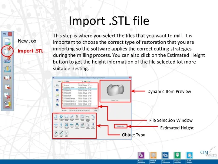
- 18. Import .STL file This step is where you select the files that you want to mill.
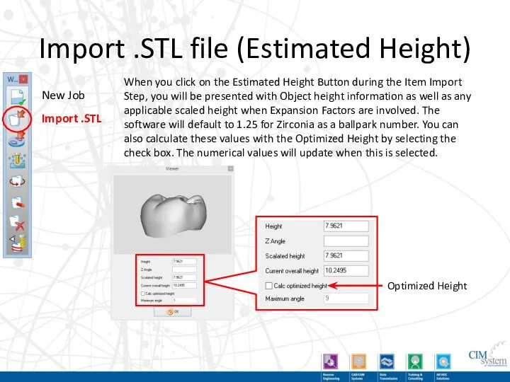
- 19. Import .STL file (Estimated Height) When you click on the Estimated Height Button during the Item
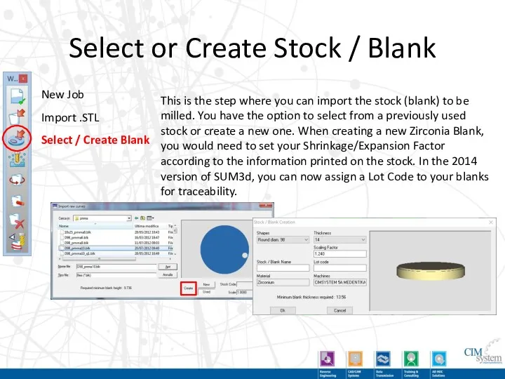
- 20. Select or Create Stock / Blank This is the step where you can import the stock
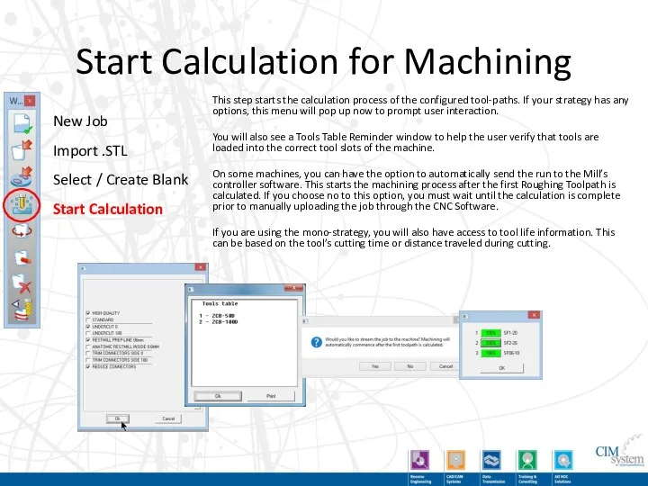
- 21. Start Calculation for Machining This step starts the calculation process of the configured tool-paths. If your
- 22. Demo of Main Steps
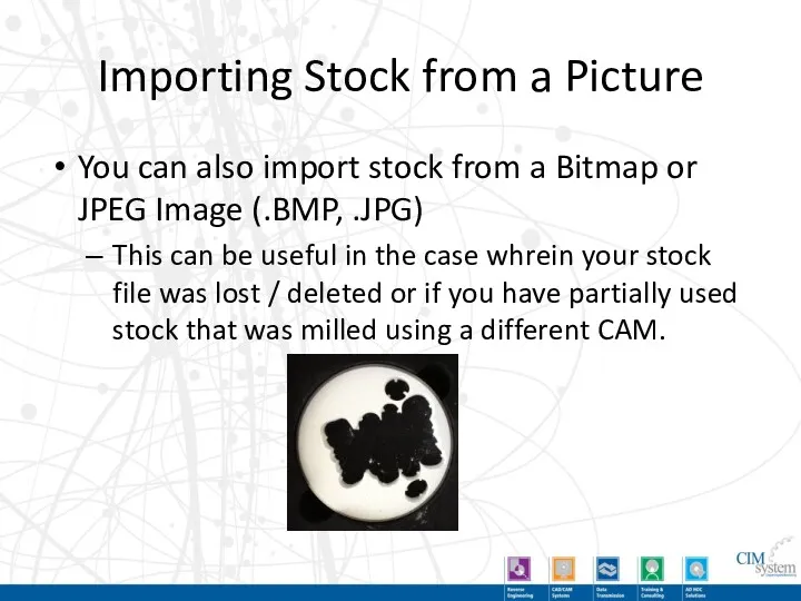
- 23. Importing Stock from a Picture You can also import stock from a Bitmap or JPEG Image
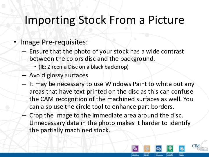
- 24. Importing Stock From a Picture Image Pre-requisites: Ensure that the photo of your stock has a
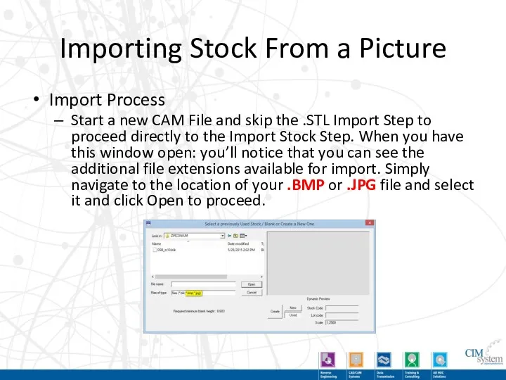
- 25. Importing Stock From a Picture Import Process Start a new CAM File and skip the .STL
- 26. Importing Stock From a Picture Import Process Because the image does not contain any information about
- 27. Importing Stock From a Picture Import Process We will now find that the stock has been
- 28. Optional Steps - Move / Rotate Parts This command allows the user to manually re-position restorations
- 29. Optional Steps - Add Support Pins This command allows the user to manually place support pins
- 30. Optional Steps - Remove Items This command is used to erase a part of the items'
- 31. Optional Steps - Simulation New Job Import .STL Select / Create Blank Start Calculation Move /
- 32. Demo of Optional Steps
- 33. Open Job This command allows the operator to select from an already existing CAM file to
- 34. Automatic Nesting The Automatic Nesting operation is automatically performed during the items’ import. This button allows
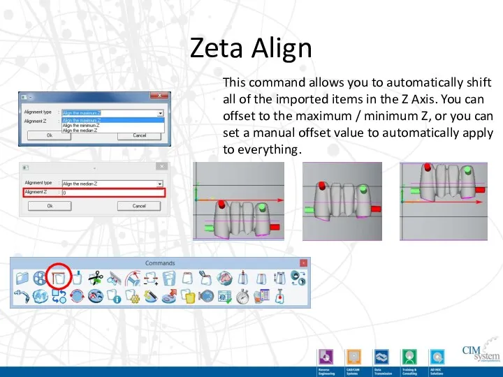
- 35. Zeta Align This command allows you to automatically shift all of the imported items in the
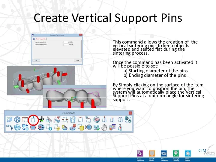
- 36. Create Vertical Support Pins This command allows the creation of the vertical sintering pins to keep
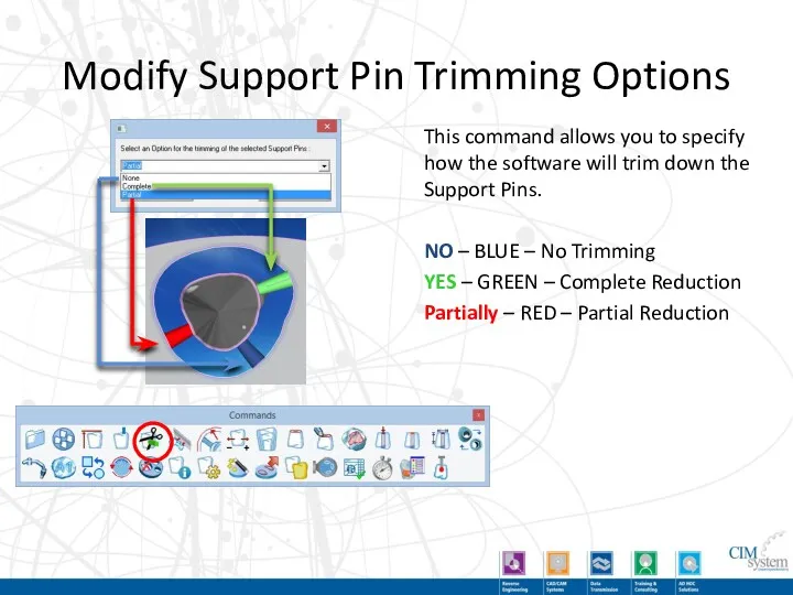
- 37. Modify Support Pin Trimming Options This command allows you to specify how the software will trim
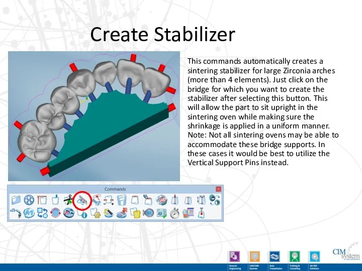
- 38. Create Stabilizer This commands automatically creates a sintering stabilizer for large Zirconia arches (more than 4
- 39. Modify Offset / Part Border Values This command allows the user to manually specify thickness of
- 40. Accurate Positioning This tool allows for full control over orientation and position of restorations using angular
- 41. Modify Shrinkage / Enlargement Factor This command allows the user to change the shrinkage factor. This
- 42. Automatically Detect Prep Line This command allows the user to creates 2 curves to segment off
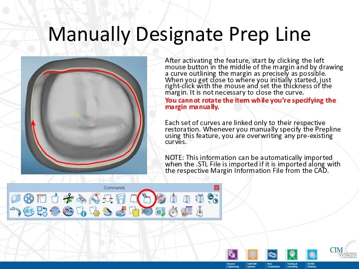
- 43. Manually Designate Prep Line After activating the feature, start by clicking the left mouse button in
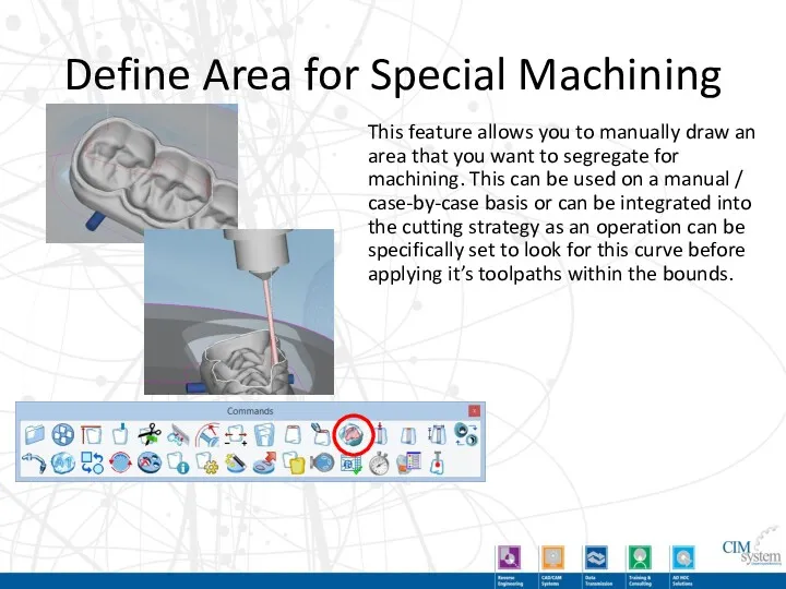
- 44. Define Area for Special Machining This feature allows you to manually draw an area that you
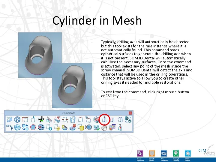
- 45. Cylinder in Mesh Typically, drilling axes will automatically be detected but this tool exists for the
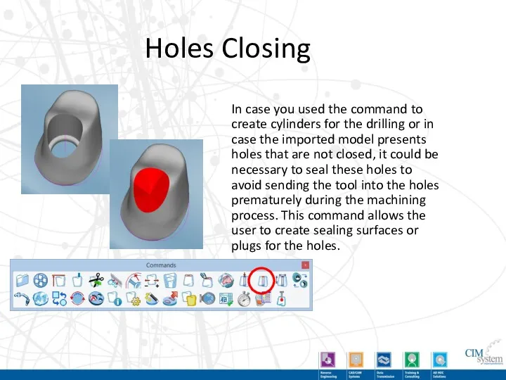
- 46. Holes Closing In case you used the command to create cylinders for the drilling or in
- 47. Modify Hole Dimension Here you can change the values for the diameter of the screw access
- 48. Replace Interface This feature allows the user to replace the interface geometry of an implant abutment
- 49. Secondary Axis This command defines the secondary machining axis for the bars and attachments. By clicking
- 50. Engraving Engraving allows the manufacturer to mill an identification code on the objects, to simplify the
- 51. Change Object Type This command allows the operator to change the type of the selected object
- 52. Rotation of the Blank This function allows you to rotate the disc within a fixure. This
- 53. Delete Curves This option allows the operator to delete a part border that is showing present
- 54. Info This command allows the operator to select an imported object and display all of the
- 55. Generate Blank This command allows an operator to create multiple blanks very quickly and store them
- 56. Save Partially Used Stock This command allows the operator to export the stock that is in
- 57. Assign Machining status Optional Module
- 58. Equipment This command allows the user to manually import the fixture of the machine that holds
- 59. Create Report This icon allows to create a personalized report based on your current loaded job.
- 60. Milling Time Calculation Using pre-determined time values assigned to the machine in the Machines Archive, the
- 61. Show residual material In order to use this feature, the calculation of the job must first
- 62. Dimensional Verification This command allows the dimensional verification and certification of the implants just after the
- 63. Demo of Secondary Toolbar Buttons
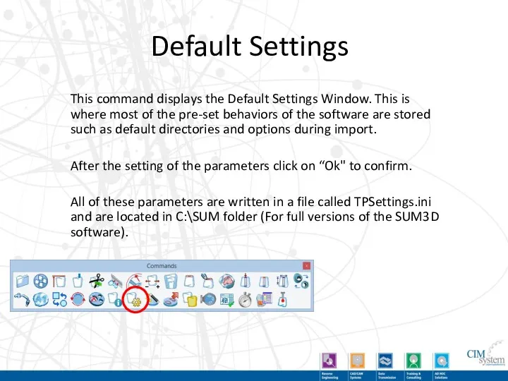
- 64. Default Settings This command displays the Default Settings Window. This is where most of the pre-set
- 65. Default Settings – General Configuration Toggle Interface Level Icon Size Engraving Settings Logo Settings Mesh Filtering
- 66. Default Settings – Database Not Used for Dental
- 67. Default Settings – Equipment Default Directory for the Fixtures / Holders
- 68. Default Settings – Tools About Software User Manual Machines Archive Tool Room / Archive Materials Archive
- 69. Default Settings – Materials Folders Change the default directory names that the software will look for
- 70. Default Settings – Report Report Output Format Report Template Default Directory for Output Additional Report Options
- 71. Default Settings – Margins Default Margin Thickness This value should match the margin thickness that you
- 72. Default Settings – Support Pins In this setting tab we can specify multiple optional parameters for
- 73. Default Settings – Stock Default Directories for New / Used Stock. Stock Import Options Auto Nesting
- 74. Default Settings – Strategy Default Directories for Importing / Exporting Strategies from. Strategy Lock Parallel Computing
- 75. Default Settings – Model Import Default Directories for Importing restorations for milling Individualized Part Borders /
- 76. Default Settings – Job Files Default Directories for placement of Job (.CAM) Files. Automatic Job Naming
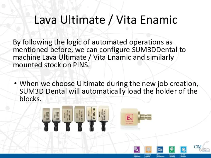
- 77. Lava Ultimate / Vita Enamic By following the logic of automated operations as mentioned before, we
- 78. New Job Creation – Lava Ultimate / VE
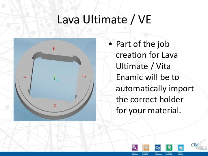
- 79. Lava Ultimate / VE Part of the job creation for Lava Ultimate / Vita Enamic will
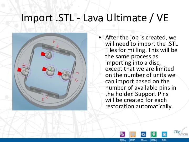
- 80. Import .STL - Lava Ultimate / VE After the job is created, we will need to
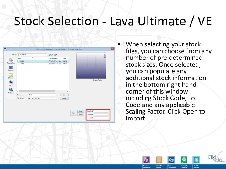
- 81. Stock Selection - Lava Ultimate / VE When selecting your stock files, you can choose from
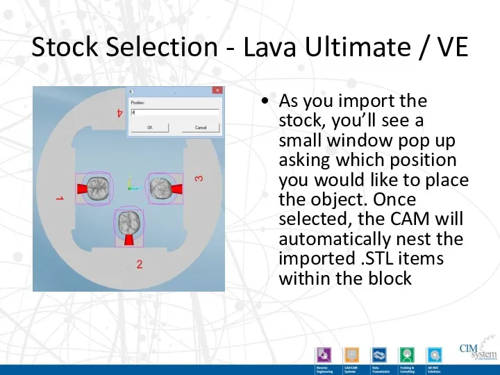
- 82. Stock Selection - Lava Ultimate / VE As you import the stock, you’ll see a small
- 84. Скачать презентацию
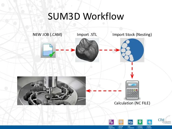
SUM3D Workflow
NEW JOB (.CAM)
Import .STL
Import Stock (Nesting)
Calculation (NC FILE)
SUM3D Workflow
NEW JOB (.CAM)
Import .STL
Import Stock (Nesting)
Calculation (NC FILE)
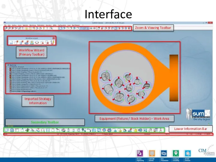
Interface
Zoom & Viewing Toolbar
Workflow Wizard
(Primary Toolbar)
Imported Strategy
Information
Equipment (Fixture /
Interface
Zoom & Viewing Toolbar
Workflow Wizard
(Primary Toolbar)
Imported Strategy
Information
Equipment (Fixture /
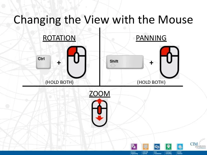
Changing the View with the Mouse
ROTATION
PANNING
ZOOM
+
+
(HOLD BOTH)
(HOLD BOTH)
Changing the View with the Mouse
ROTATION
PANNING
ZOOM
+
+
(HOLD BOTH)
(HOLD BOTH)
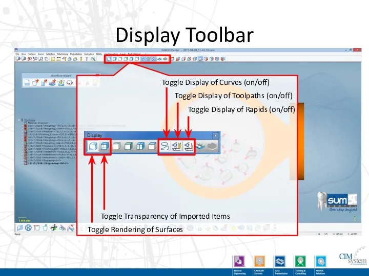
Display Toolbar
Toggle Rendering of Surfaces
Toggle Transparency of Imported Items
Toggle Display of
Display Toolbar
Toggle Rendering of Surfaces
Toggle Transparency of Imported Items
Toggle Display of
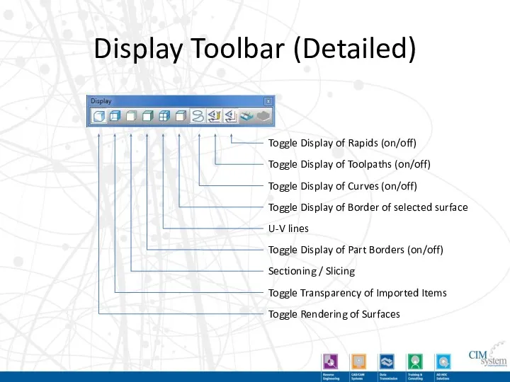
Display Toolbar (Detailed)
Toggle Rendering of Surfaces
Toggle Transparency of Imported Items
Sectioning /
Display Toolbar (Detailed)
Toggle Rendering of Surfaces
Toggle Transparency of Imported Items
Sectioning /
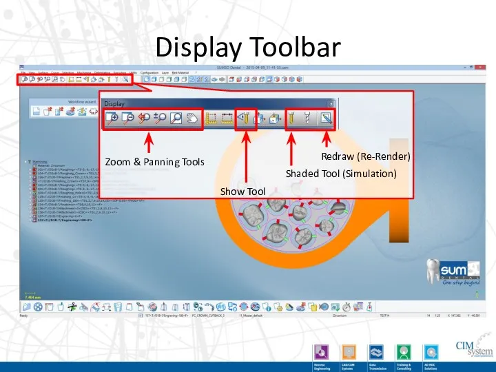
Display Toolbar
Show Tool
Shaded Tool (Simulation)
Redraw (Re-Render)
Zoom & Panning Tools
Display Toolbar
Show Tool
Shaded Tool (Simulation)
Redraw (Re-Render)
Zoom & Panning Tools
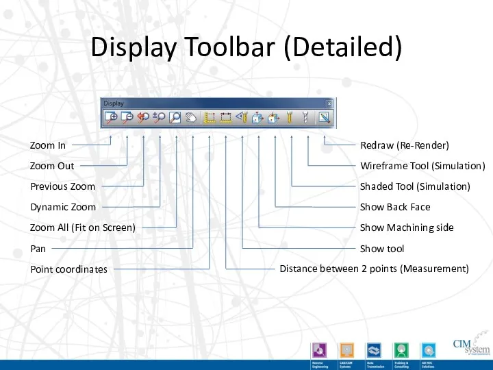
Display Toolbar (Detailed)
Distance between 2 points (Measurement)
Show tool
Show Machining side
Show Back
Display Toolbar (Detailed)
Distance between 2 points (Measurement)
Show tool
Show Machining side
Show Back
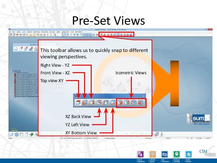
Pre-Set Views
Top view XY
Front View - XZ
Right View - YZ
XZ Back
Pre-Set Views
Top view XY
Front View - XZ
Right View - YZ
XZ Back
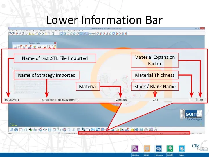
Lower Information Bar
Name of last .STL File Imported
Name of Strategy Imported
Material
Stock
Lower Information Bar
Name of last .STL File Imported
Name of Strategy Imported
Material
Stock
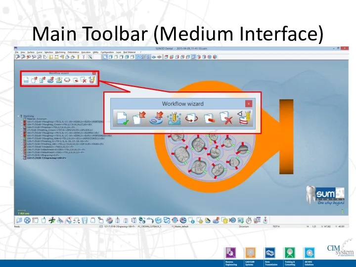
Main Toolbar (Medium Interface)
Main Toolbar (Medium Interface)
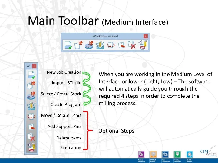
Main Toolbar (Medium Interface)
New Job Creation
Import .STL file
Select / Create Stock
Create
Main Toolbar (Medium Interface)
New Job Creation
Import .STL file
Select / Create Stock
Create
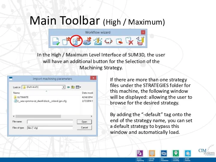
Main Toolbar (High / Maximum)
In the High / Maximum Level Interface
Main Toolbar (High / Maximum)
In the High / Maximum Level Interface
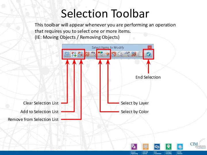
Selection Toolbar
Clear Selection List
Add to Selection List
Remove from Selection List
Select by
Selection Toolbar
Clear Selection List
Add to Selection List
Remove from Selection List
Select by
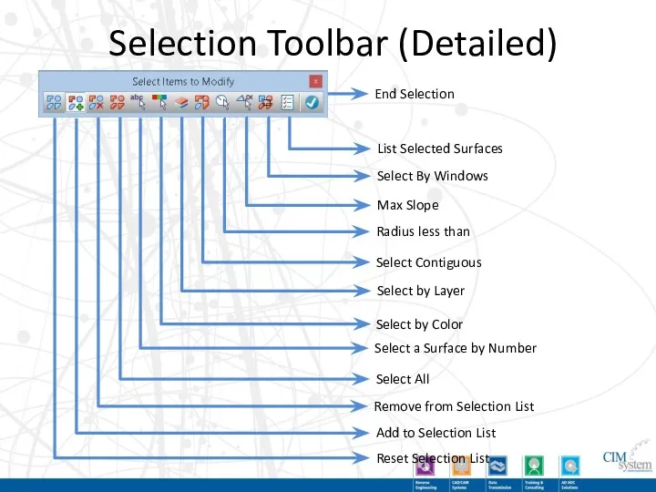
Selection Toolbar (Detailed)
Reset Selection List
Add to Selection List
Remove from Selection List
Select
Selection Toolbar (Detailed)
Reset Selection List
Add to Selection List
Remove from Selection List
Select
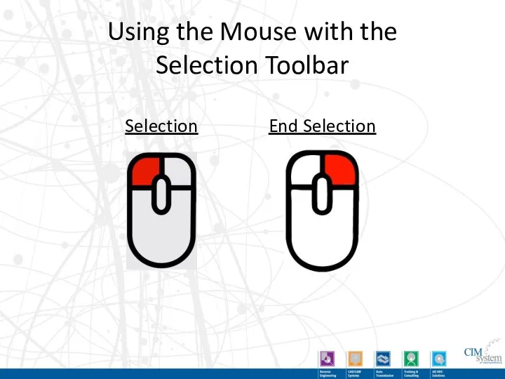
Using the Mouse with the
Selection Toolbar
Selection
End Selection
Using the Mouse with the
Selection Toolbar
Selection
End Selection
New Job Creation
This step creates a new empty .CAM file. All
New Job Creation
This step creates a new empty .CAM file. All
Import .STL file
This step is where you select the files that
Import .STL file
This step is where you select the files that
Import .STL file (Estimated Height)
When you click on the Estimated Height
Import .STL file (Estimated Height)
When you click on the Estimated Height
Select or Create Stock / Blank
This is the step where you
Select or Create Stock / Blank
This is the step where you
Start Calculation for Machining
This step starts the calculation process of the
Start Calculation for Machining
This step starts the calculation process of the
Demo of Main Steps
Demo of Main Steps
Importing Stock from a Picture
You can also import stock from a
Importing Stock from a Picture
You can also import stock from a
Importing Stock From a Picture
Image Pre-requisites:
Ensure that the photo of your
Importing Stock From a Picture
Image Pre-requisites:
Ensure that the photo of your
Importing Stock From a Picture
Import Process
Start a new CAM File and
Importing Stock From a Picture
Import Process
Start a new CAM File and

Importing Stock From a Picture
Import Process
Because the image does not contain
Importing Stock From a Picture
Import Process
Because the image does not contain
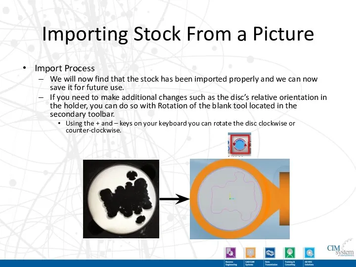
Importing Stock From a Picture
Import Process
We will now find that the
Importing Stock From a Picture
Import Process
We will now find that the
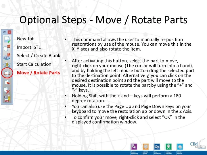
Optional Steps - Move / Rotate Parts
This command allows the user
Optional Steps - Move / Rotate Parts
This command allows the user
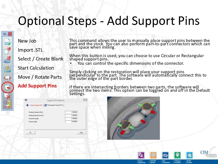
Optional Steps - Add Support Pins
This command allows the user to
Optional Steps - Add Support Pins
This command allows the user to
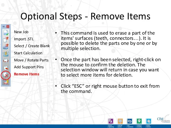
Optional Steps - Remove Items
This command is used to erase a
Optional Steps - Remove Items
This command is used to erase a
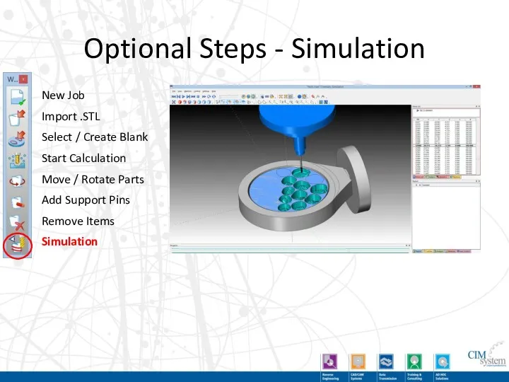
Optional Steps - Simulation
New Job
Import .STL
Select / Create Blank
Start Calculation
Move /
Optional Steps - Simulation
New Job
Import .STL
Select / Create Blank
Start Calculation
Move /
Demo of Optional Steps
Demo of Optional Steps
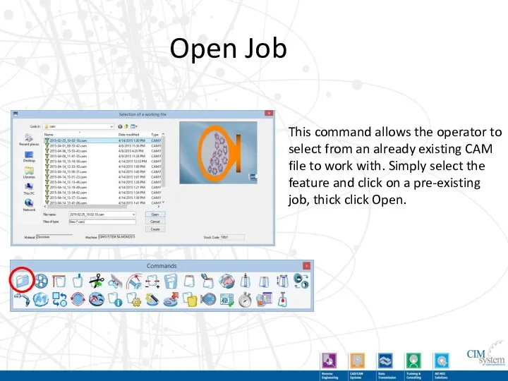
Open Job
This command allows the operator to select from an already
Open Job
This command allows the operator to select from an already
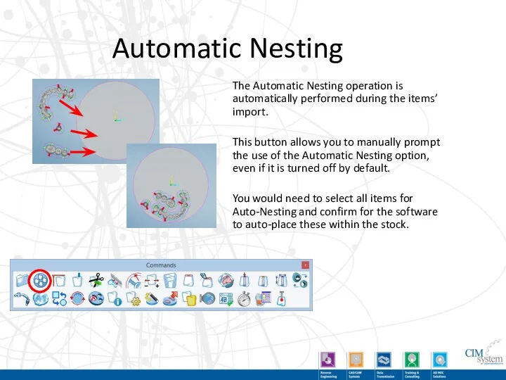
Automatic Nesting
The Automatic Nesting operation is automatically performed during the items’
Automatic Nesting
The Automatic Nesting operation is automatically performed during the items’
Zeta Align
This command allows you to automatically shift all of the
Zeta Align
This command allows you to automatically shift all of the
Create Vertical Support Pins
This command allows the creation of the vertical
Create Vertical Support Pins
This command allows the creation of the vertical
Modify Support Pin Trimming Options
This command allows you to specify how
Modify Support Pin Trimming Options
This command allows you to specify how
Create Stabilizer
This commands automatically creates a sintering stabilizer for large Zirconia
Create Stabilizer
This commands automatically creates a sintering stabilizer for large Zirconia
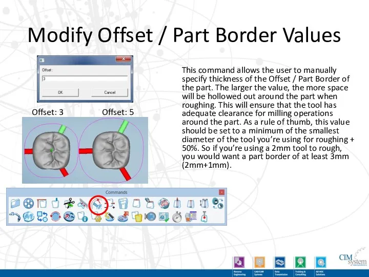
Modify Offset / Part Border Values
This command allows the user to
Modify Offset / Part Border Values
This command allows the user to
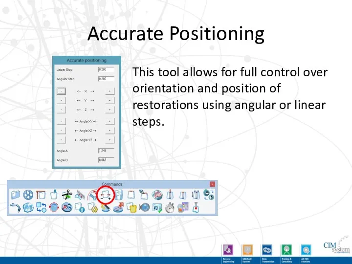
Accurate Positioning
This tool allows for full control over orientation and position
Accurate Positioning
This tool allows for full control over orientation and position
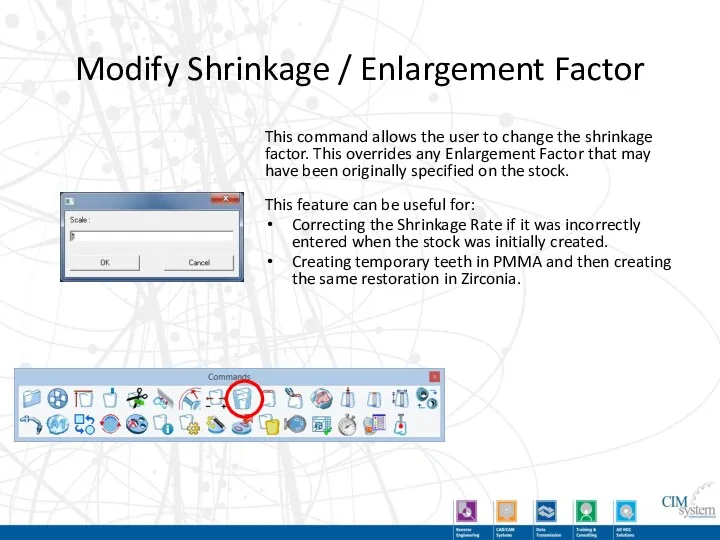
Modify Shrinkage / Enlargement Factor
This command allows the user to change
Modify Shrinkage / Enlargement Factor
This command allows the user to change
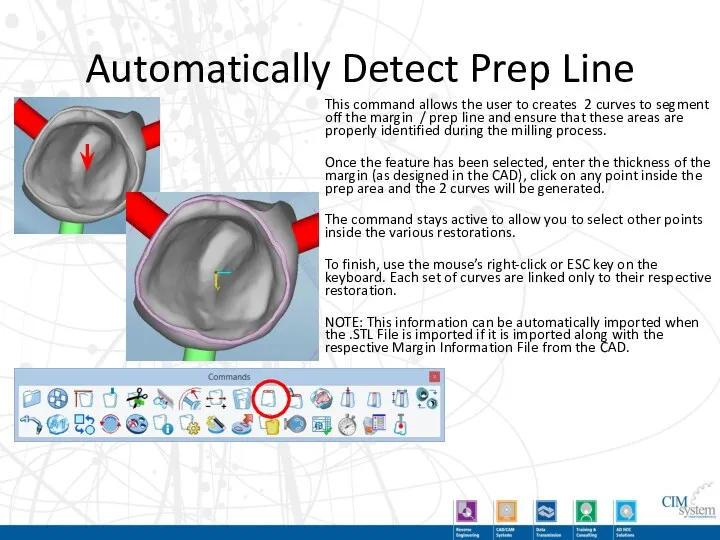
Automatically Detect Prep Line
This command allows the user to creates 2
Automatically Detect Prep Line
This command allows the user to creates 2
Manually Designate Prep Line
After activating the feature, start by clicking the
Manually Designate Prep Line
After activating the feature, start by clicking the
Define Area for Special Machining
This feature allows you to manually draw
Define Area for Special Machining
This feature allows you to manually draw
Cylinder in Mesh
Typically, drilling axes will automatically be detected but this
Cylinder in Mesh
Typically, drilling axes will automatically be detected but this
Holes Closing
In case you used the command to create cylinders for
Holes Closing
In case you used the command to create cylinders for
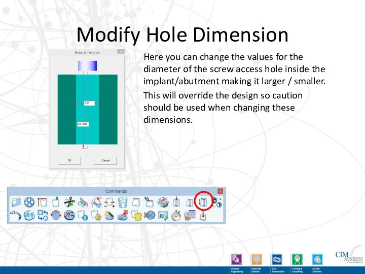
Modify Hole Dimension
Here you can change the values for the diameter
Modify Hole Dimension
Here you can change the values for the diameter
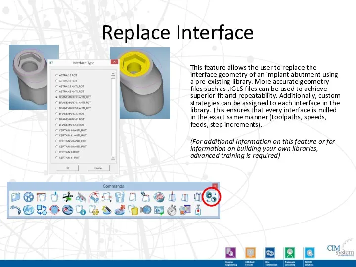
Replace Interface
This feature allows the user to replace the interface geometry
Replace Interface
This feature allows the user to replace the interface geometry
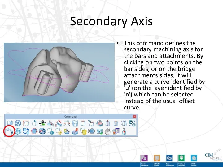
Secondary Axis
This command defines the secondary machining axis for the bars
Secondary Axis
This command defines the secondary machining axis for the bars
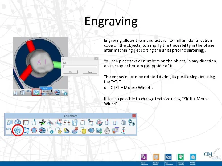
Engraving
Engraving allows the manufacturer to mill an identification code on the
Engraving
Engraving allows the manufacturer to mill an identification code on the
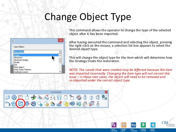
Change Object Type
This command allows the operator to change the type
Change Object Type
This command allows the operator to change the type
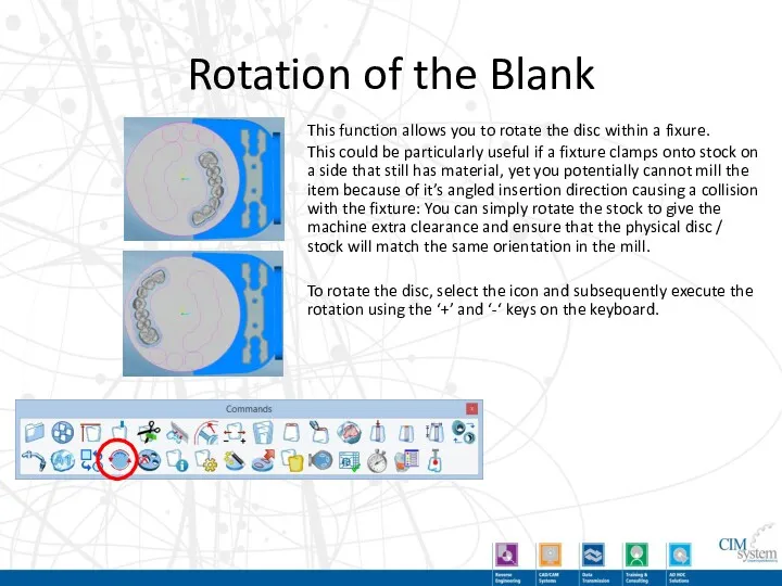
Rotation of the Blank
This function allows you to rotate the disc
Rotation of the Blank
This function allows you to rotate the disc
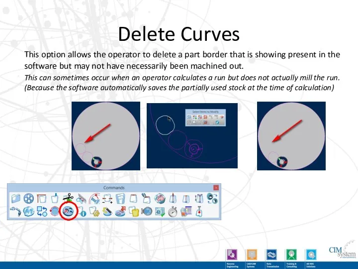
Delete Curves
This option allows the operator to delete a part border
Delete Curves
This option allows the operator to delete a part border

Info
This command allows the operator to select an imported object and
Info
This command allows the operator to select an imported object and
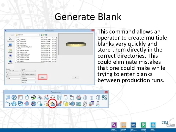
Generate Blank
This command allows an operator to create multiple blanks very
Generate Blank
This command allows an operator to create multiple blanks very
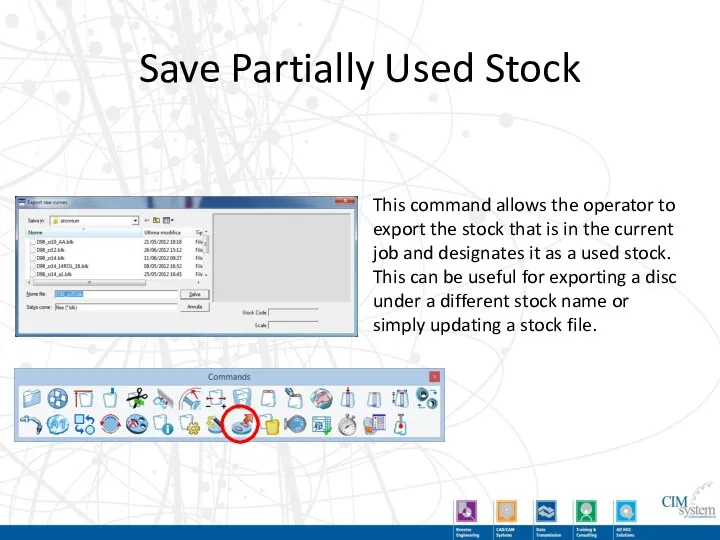
Save Partially Used Stock
This command allows the operator to export the
Save Partially Used Stock
This command allows the operator to export the
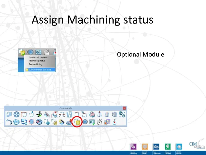
Assign Machining status
Optional Module
Assign Machining status
Optional Module
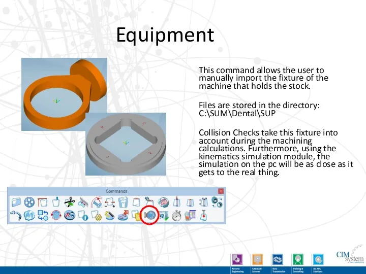
Equipment
This command allows the user to manually import the fixture of
Equipment
This command allows the user to manually import the fixture of
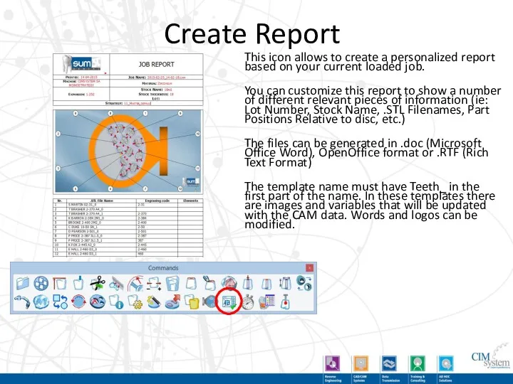
Create Report
This icon allows to create a personalized report based on
Create Report
This icon allows to create a personalized report based on
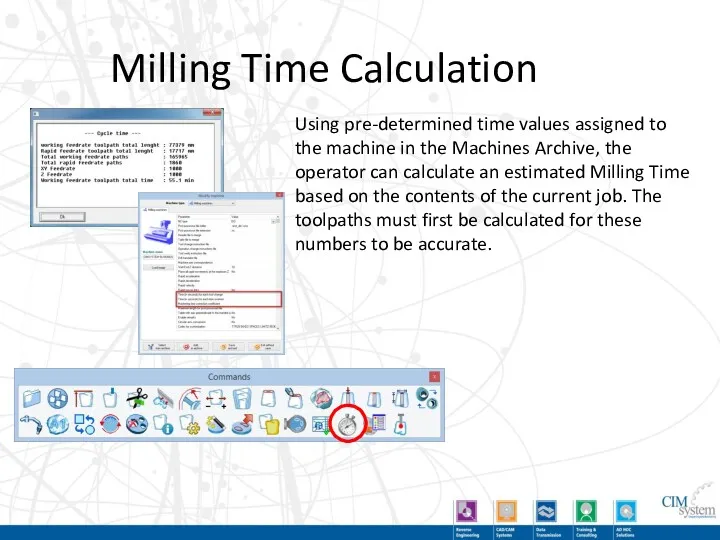
Milling Time Calculation
Using pre-determined time values assigned to the machine in
Milling Time Calculation
Using pre-determined time values assigned to the machine in
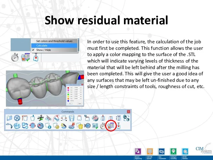
Show residual material
In order to use this feature, the calculation of
Show residual material
In order to use this feature, the calculation of
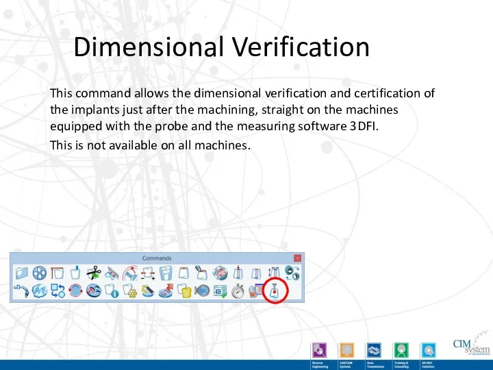
Dimensional Verification
This command allows the dimensional verification and certification of the
Dimensional Verification
This command allows the dimensional verification and certification of the
Demo of Secondary Toolbar Buttons
Demo of Secondary Toolbar Buttons
Default Settings
This command displays the Default Settings Window. This is where
Default Settings
This command displays the Default Settings Window. This is where
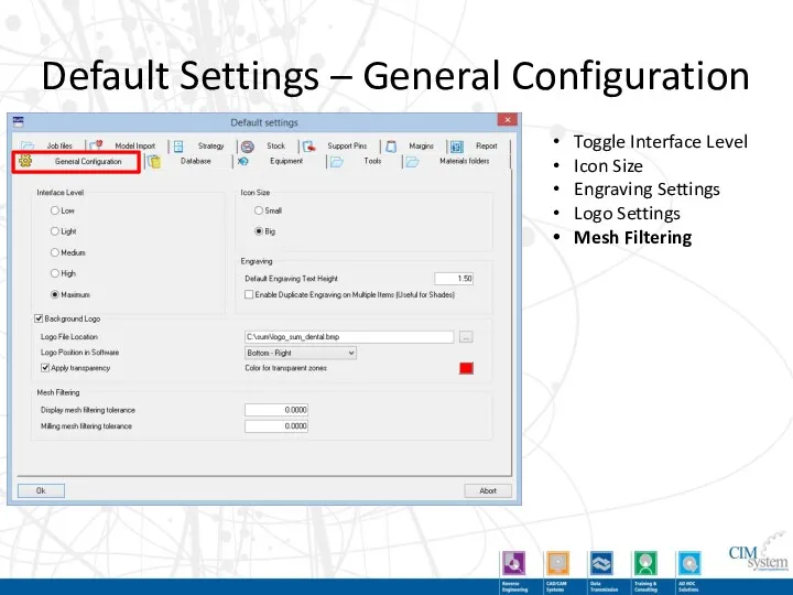
Default Settings – General Configuration
Toggle Interface Level
Icon Size
Engraving Settings
Logo Settings
Mesh Filtering
Default Settings – General Configuration
Toggle Interface Level
Icon Size
Engraving Settings
Logo Settings
Mesh Filtering
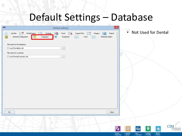
Default Settings – Database
Not Used for Dental
Default Settings – Database
Not Used for Dental
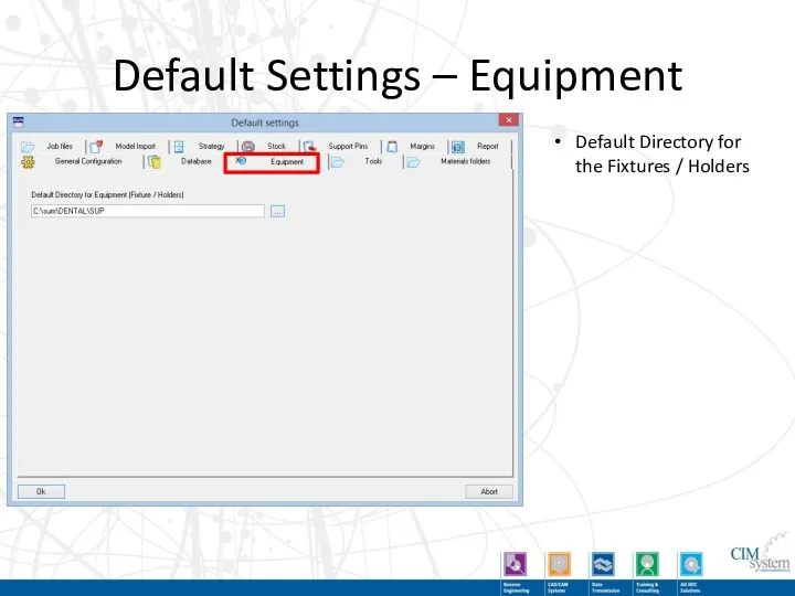
Default Settings – Equipment
Default Directory for the Fixtures / Holders
Default Settings – Equipment
Default Directory for the Fixtures / Holders
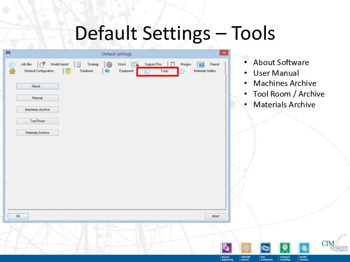
Default Settings – Tools
About Software
User Manual
Machines Archive
Tool Room / Archive
Materials Archive
Default Settings – Tools
About Software
User Manual
Machines Archive
Tool Room / Archive
Materials Archive
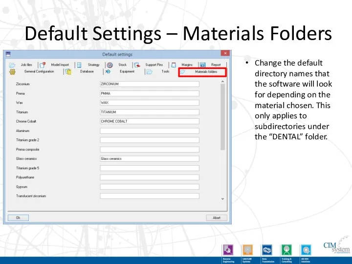
Default Settings – Materials Folders
Change the default directory names that the
Default Settings – Materials Folders
Change the default directory names that the

Default Settings – Report
Report Output Format
Report Template
Default Directory for Output
Additional Report
Default Settings – Report
Report Output Format
Report Template
Default Directory for Output
Additional Report
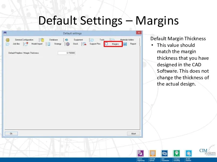
Default Settings – Margins
Default Margin Thickness
This value should match the margin
Default Settings – Margins
Default Margin Thickness
This value should match the margin
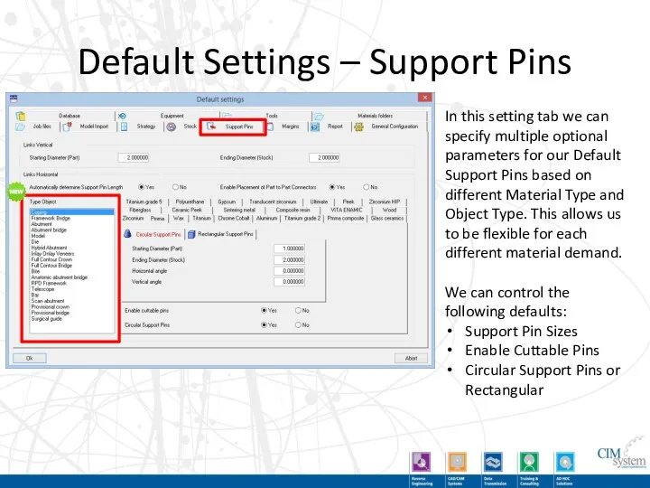
Default Settings – Support Pins
In this setting tab we can specify
Default Settings – Support Pins
In this setting tab we can specify
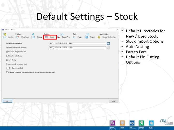
Default Settings – Stock
Default Directories for New / Used Stock.
Stock Import
Default Settings – Stock
Default Directories for New / Used Stock.
Stock Import
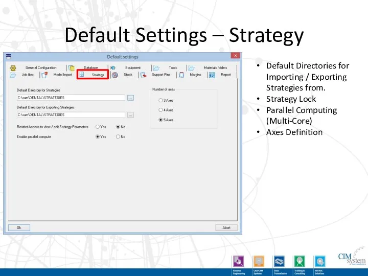
Default Settings – Strategy
Default Directories for Importing / Exporting Strategies from.
Strategy
Default Settings – Strategy
Default Directories for Importing / Exporting Strategies from.
Strategy
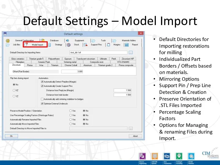
Default Settings – Model Import
Default Directories for Importing restorations for milling
Individualized
Default Settings – Model Import
Default Directories for Importing restorations for milling
Individualized
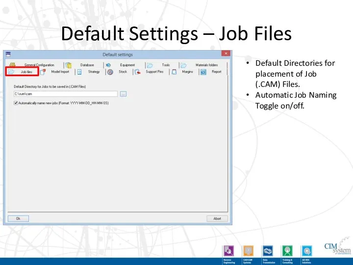
Default Settings – Job Files
Default Directories for placement of Job (.CAM)
Default Settings – Job Files
Default Directories for placement of Job (.CAM)
Lava Ultimate / Vita Enamic
By following the logic of automated operations
Lava Ultimate / Vita Enamic
By following the logic of automated operations
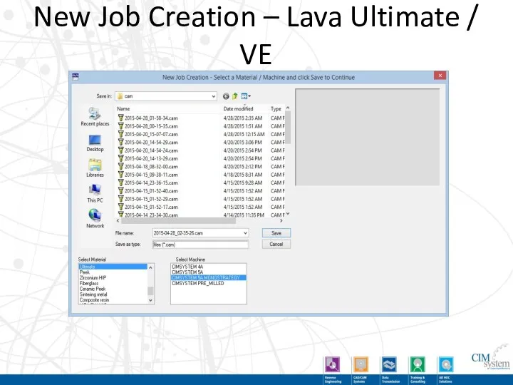
New Job Creation – Lava Ultimate / VE
New Job Creation – Lava Ultimate / VE
Lava Ultimate / VE
Part of the job creation for Lava Ultimate
Lava Ultimate / VE
Part of the job creation for Lava Ultimate
Import .STL - Lava Ultimate / VE
After the job is created,
Import .STL - Lava Ultimate / VE
After the job is created,
Stock Selection - Lava Ultimate / VE
When selecting your stock files,
Stock Selection - Lava Ultimate / VE
When selecting your stock files,
Stock Selection - Lava Ultimate / VE
As you import the stock,
Stock Selection - Lava Ultimate / VE
As you import the stock,
 Современная концепция естественного вскармливания
 Deontology. Introduction
 Фармакология витамина Е
 Разбор клинического случая. Демонстрация пациента
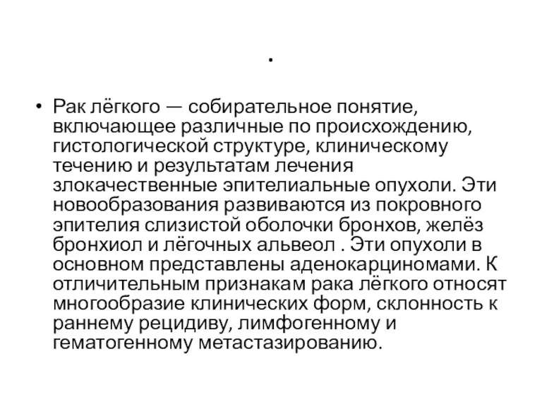 Рак лёгкого
 Тағамдық аллергия
 Сестринская помощь пациентам с впервые выявленной бронхиальной астмой
 Онкогенні папіломавіруси
 Тістердің бұзылуы және олардың жоғалту кезіндегі морфологиялық және функционалды өзгерістер
 Нарушения ритма сердца. Синдром нарушения ритма
 Tratamentul Diabetului zaharat 2
 Розацеа. Этиология и патогенез
 Энтеробактерии. Эшерихии
 Лечение опухолей толстого кишечника: лучевая и химиотерапия
 Лечебная физкультура при инфаркте миокарда
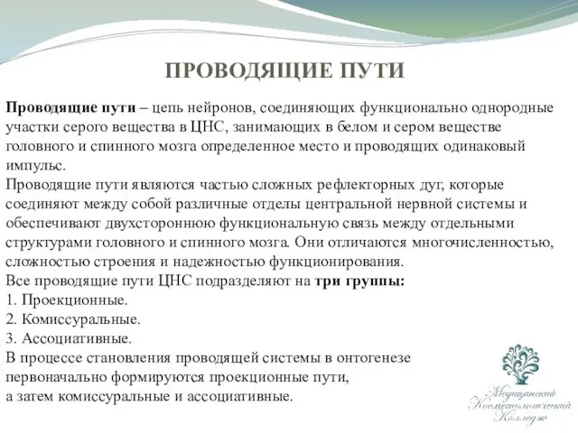 Проводящие пути центральной нервной системы
 Факторы иммунитета. Новый мир COVID-19. Инфекции и прививки
 Патофизиология эндокринной системы
 Целиакия у детей. Дифференциальный диагноз
 Вирус бешенства
 Лазеры в хирургии
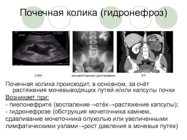 Неотложная радиология в урологии. Почечная колика
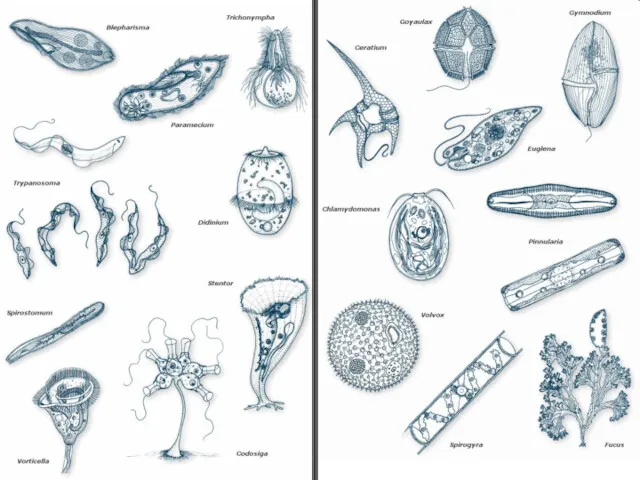 Протиста (только жгутиковые)
 Акне (Угри)
 Фиброз и цирроз печени. Гемахроматоз. Болезнь Вильсона
 Методы диагностики микобактерий туберкулеза
 Чорна смерть. Чума
 Хронический панкреатит. Диагностика и лечение