- Air Treatment system

Содержание
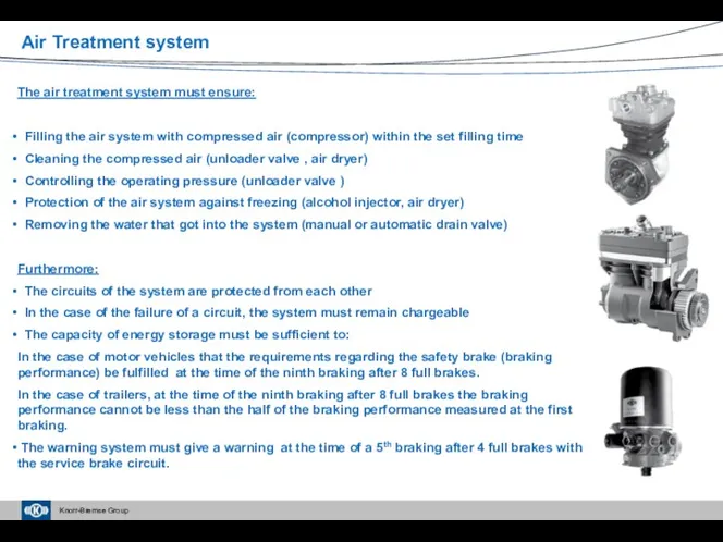
- 2. Air Treatment system The air treatment system must ensure: Filling the air system with compressed air
- 3. In the case of an air dryer equipped with integrated unloader valve In the case of
- 4. Air treatment system Delivery phase
- 5. End of regeneration phase Air treatment system
- 6. Installation environment of the air treatment system. What do you have to pay attention to during
- 7. Technological development of compressors Development of compressors 1980 1995 2000 2005 2010 2015 1985 1990 Monoblock
- 8. Components: 1 Connecting rod bearing 2 Crankshaft 3 Piston 4 Inlet reed 5 Valve plate 6
- 9. Suction phase Air treatment system Delivery phase
- 10. 92 mm piston 650 – 720 cc twin cylinder 92 mm piston 360 cc single cylinder
- 11. ESS function Delivery phase Idle phase Change of cylinder head pressure in idle phase Power consumption
- 12. New ESS structure Valve piston Connectors: Valve seat 0 - Intake manifold Suction hole 2 –
- 13. Air treatment system ESS structure in the case of 1 and 2-cylinder compressors
- 14. Development of the cylinder head structure – Reduction of the temperature of exhausted air Air-cooled Water-cooled
- 15. Development of the crankcase – Reduction of oil carry-over Split-case structure, air-cooling Monoblock design Monoblock design
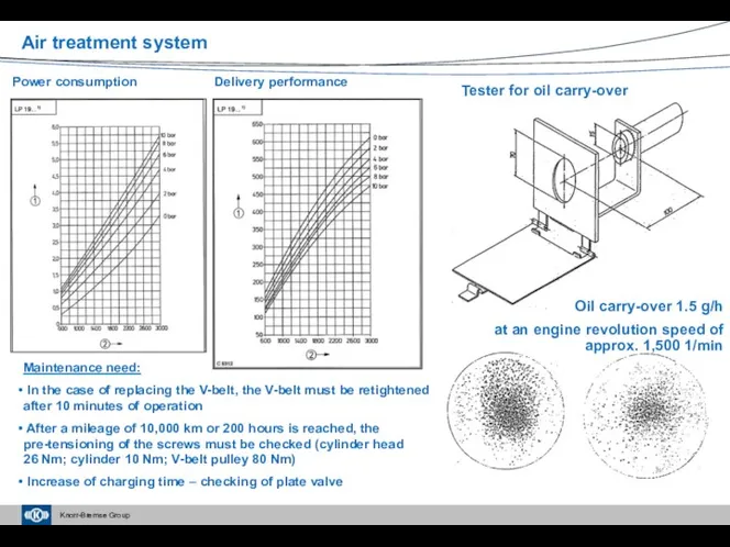
- 16. Tester for oil carry-over Power consumption Delivery performance Maintenance need: In the case of replacing the
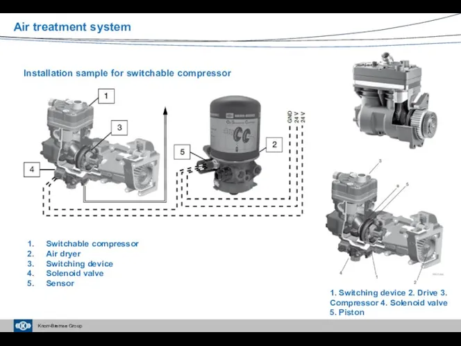
- 17. Air treatment system Installation sample for switchable compressor Switchable compressor Air dryer Switching device Solenoid valve
- 18. Air treatment system
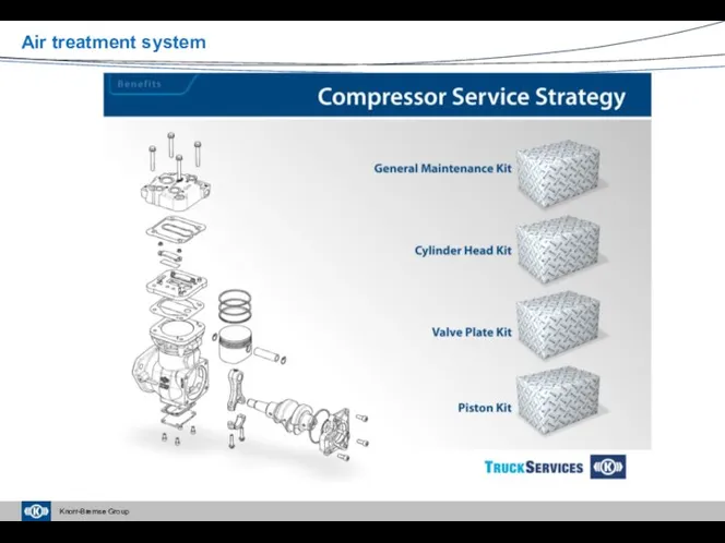
- 19. Compressors – Current service information Air treatment system
- 20. Automatic alcohol injector (LA41..; 0 484 451 002 - 018): Suggestions for application: Devices without a
- 21. Unloader valves (DR35..; AC135..; 0 481 039 …; 0 481 042 …) Functions: Delivery phase Exhaust
- 22. Delivery phase Air treatment system Idle phase External charging Tyre inflation
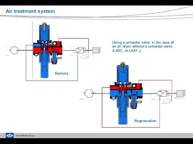
- 23. Air treatment system Using a unloader valve in the case of an air dryer without a
- 24. Governor: A special version of unloader valves that is used mostly on vehicles manufactured in Scandinavia
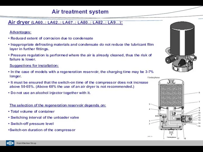
- 25. Air treatment system Air dryer (LA60..; LA62..; LA67..; LA80..; LA82..; LA9…): Advantages: Reduced extent of corrosion
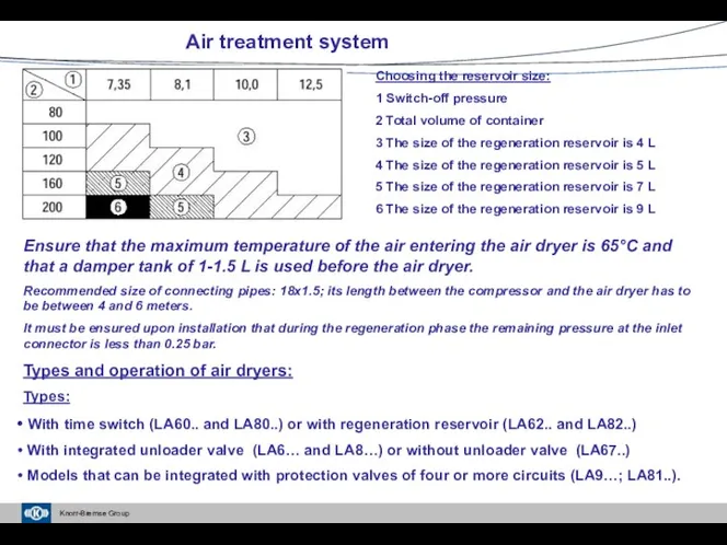
- 26. Air treatment system Choosing the reservoir size: 1 Switch-off pressure 2 Total volume of container 3
- 27. Increasing complexity 1980 1995 2000 2005 2010 2015 1985 1990 Development of air treatment systems 2020
- 28. LA86 LA87 LA82 / LA80 Overview of air dryers LA90 LA81 Independent air dryer with integrated
- 29. 6 Cartridge material 5 Filter 7 Non-return valve 16 Throttle 3 Outlet piston 1 Silencer 4
- 30. 4 Delivery phase Regeneration Air treatment system Operation of air dryer LA67.. or LA87..
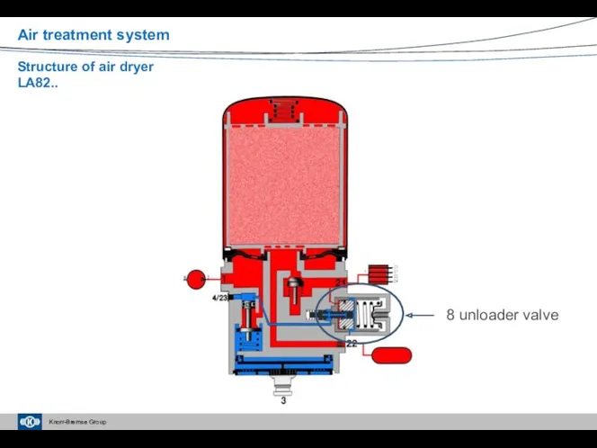
- 31. Air treatment system Structure of air dryer LA82..
- 32. Delivery phase Regeneration Air treatment system Operation of air dryer LA82..
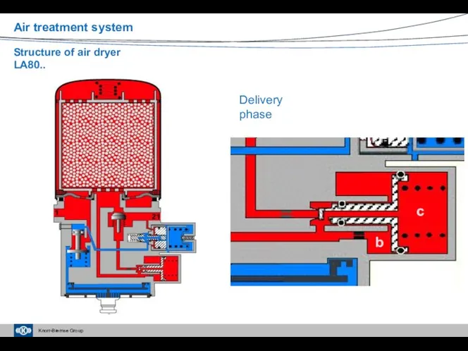
- 33. Delivery phase b c Air treatment system Structure of air dryer LA80..
- 34. Regeneration b c Air treatment system Structure of air dryer LA80..
- 35. Air dryer LA9… and LA81.. for the complex air processing units APU (ZB45..; ZB47..) LA9… Air
- 36. Semi-electronic air dryer (EL9…) Cartridges and heaters Intelligent pressure regulation and regeneration control by the central
- 37. Auxiliary equipment: Drain valve Silencers Threaded design Snap catch design EE 4206 EE 4203 Air treatment
- 38. Cartridge Service Manual / Film and Documentation For a quick replacement and service of subassemblies and
- 39. Cartridge (4) Cartridge and Sensor Double Pressure Sensor (5) Service Manual / Film and Documentation For
- 40. Air dryer units – Current service information Air treatment system
- 41. Charging valves: Characteristics: Opening pressure, closing or secured pressure When installing, care must be taken to
- 42. Charging valve with limited backflow (DR42..) Air treatment system Charging At the end of charging Connector
- 43. Charging valve without backflow (DR43..) Air treatment system Connector 1 pressure-free At the end of charging
- 44. Charging valve with backflow (DR41..) Air treatment system Pressure fall on connector 1 At the end
- 45. Pressure limiting valve: AC15.. and DB11.. Air treatment system Recharging Charging Closing
- 46. The four-circuit protection valve (AE41..; AE44..; AE45..; AE46..; AE48…): Its function: Ensuring the so-called priority order
- 47. Types of the four-circuit protection valves: Line Parallel With auxiliary function When installing, take care to
- 48. Parallel four-circuit protection valve (AE4170) without priority Pressure-free system Air treatment system
- 49. At the end of charging process Air treatment system Pressure recovery
- 50. In the case of circuit damage, without recharge In the case of circuit damage, with recharge
- 51. In the case of recharge, the pressure of undamaged circuits can increase up to the opening
- 52. Line four-circuit protection valve (AE4158) Air treatment system
- 53. Partially charged circuit II with which the residual braking performance can be achieved Ring “K” ensures
- 54. Charged operating circuits Fully charged system Air treatment system
- 55. Circuit 22 is damaged and there is no recharge Air treatment system
- 56. The undamaged circuit can be charged up to the opening pressure of the damaged circuit This
- 57. With a damaged operating circuit, the system cannot be charged if the opening pressure of the
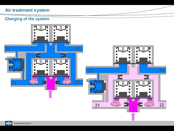
- 58. New four-circuit protection valves according to EG-R 98/12 (AE46..; AE48.. ) In the case of a
- 59. Charging of the system Air treatment system
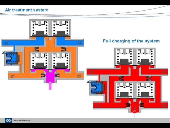
- 60. Full charging of the system Air treatment system
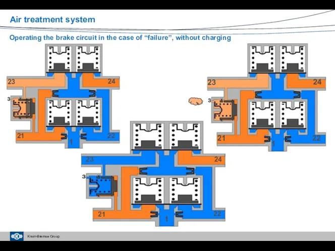
- 61. Operating the brake circuit in the case of “failure”, without charging Air treatment system
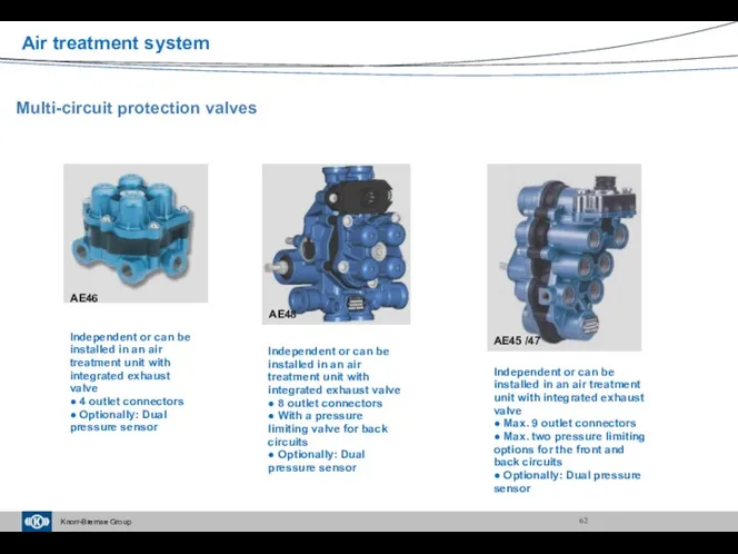
- 62. Multi-circuit protection valves AE45 /47 AE48 AE46 Independent or can be installed in an air treatment
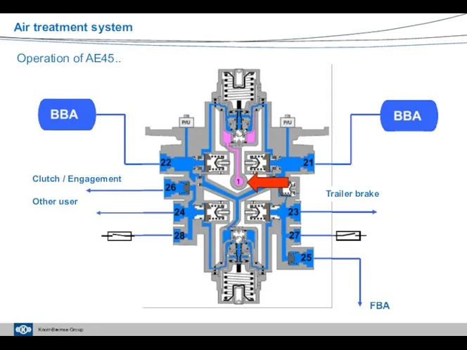
- 63. Air treatment system Operation of AE45.. Clutch / Engagement Other user Trailer brake
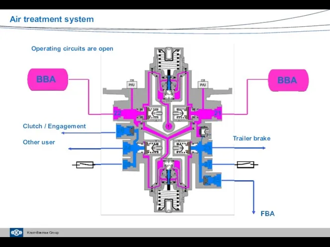
- 64. Air treatment system Clutch / Engagement Other user Trailer brake Operating circuits are open
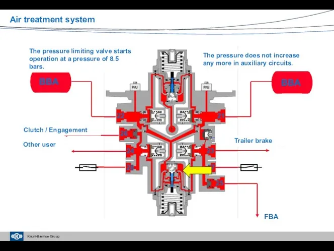
- 65. Air treatment system Clutch / Engagement Other user Trailer brake The pressure limiting valve starts operation
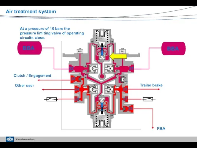
- 66. Air treatment system Clutch / Engagement Other user Trailer brake At a pressure of 10 bars
- 67. Air treatment system Clutch / Engagement Other user Trailer brake Pressure level of inlet connector reaches
- 68. Four-circuit protection valves – Current service information Air treatment system
- 69. ZB46.. ZB48 ZB45/47 Overview table of air treatment units (ZB45.., ZB46.., ZB47..; ZB48..; ZB44) ZB44 Air
- 70. Complex air treatment units – Current service information Air treatment system
- 72. Скачать презентацию
Air Treatment system
The air treatment system must ensure:
Filling the air
Air Treatment system
The air treatment system must ensure:
Filling the air
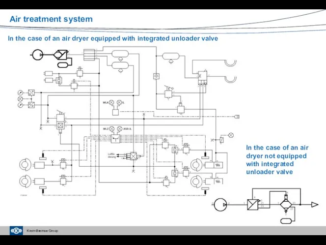
In the case of an air dryer equipped with integrated unloader
In the case of an air dryer equipped with integrated unloader
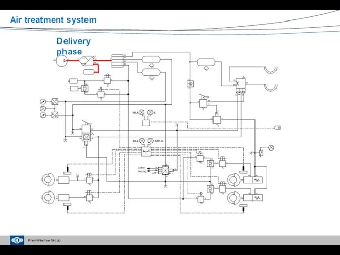
Air treatment system
Delivery phase
Air treatment system
Delivery phase
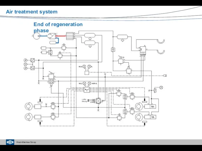
End of regeneration phase
Air treatment system
End of regeneration phase
Air treatment system
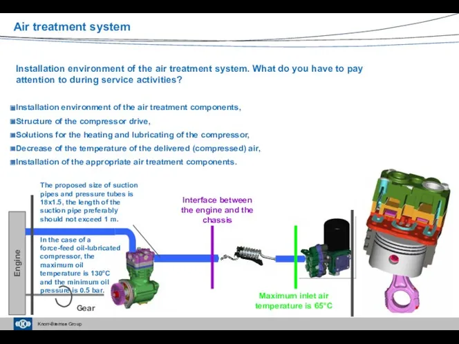
Installation environment of the air treatment system. What do you have
Installation environment of the air treatment system. What do you have
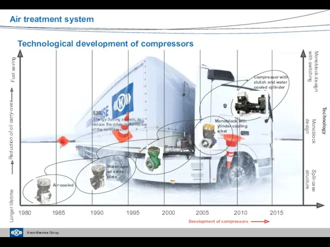
Technological development of compressors
Development of compressors
1980
1995
2000
2005
2010
2015
1985
1990
Monoblock with
cylinder cooling
jacket
Longer lifetime
Reduction
Technological development of compressors
Development of compressors
1980
1995
2000
2005
2010
2015
1985
1990
Monoblock with
cylinder cooling
jacket
Longer lifetime
Reduction
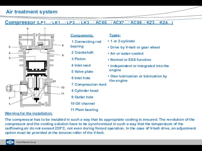
Components:
1 Connecting rod bearing
2 Crankshaft
3 Piston
4 Inlet
Components:
1 Connecting rod bearing
2 Crankshaft
3 Piston
4 Inlet
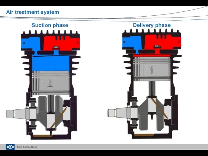
Suction phase
Air treatment system
Delivery phase
Suction phase
Air treatment system
Delivery phase
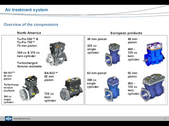
92 mm
piston
650 –
720 cc
twin
cylinder
92 mm piston
360 cc
single
cylinder
80 mm piston
225 cc
single
cylinder
86 mm
piston
460 –
720 cc
twin
cylinder
European products
Tu-Flo 550™ &
Tu-Flo 750™
70 mm
92 mm
piston
650 –
720 cc
twin
cylinder
92 mm piston
360 cc
single
cylinder
80 mm piston
225 cc
single
cylinder
86 mm
piston
460 –
720 cc
twin
cylinder
European products
Tu-Flo 550™ &
Tu-Flo 750™
70 mm
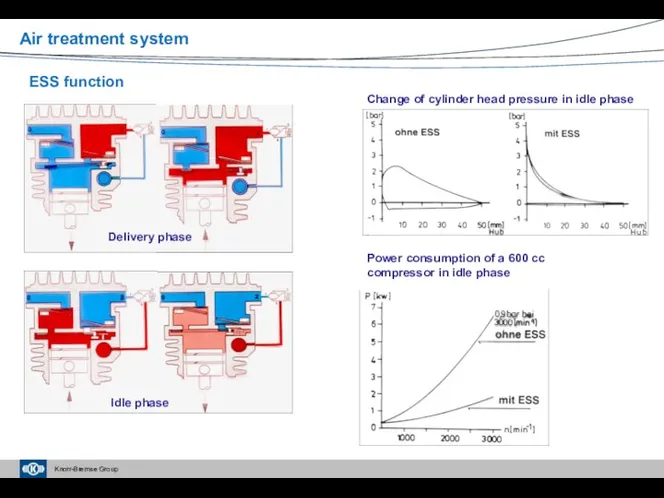
ESS function
Delivery phase
Idle phase
Change of cylinder head pressure in idle phase
Power
ESS function
Delivery phase
Idle phase
Change of cylinder head pressure in idle phase
Power
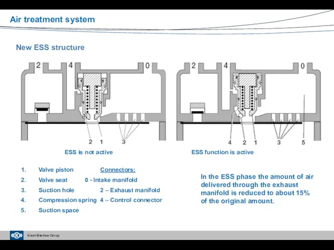
New ESS structure
Valve piston Connectors:
Valve seat 0 - Intake manifold
Suction hole 2 – Exhaust
New ESS structure
Valve piston Connectors:
Valve seat 0 - Intake manifold
Suction hole 2 – Exhaust
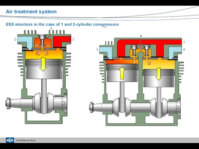
Air treatment system
ESS structure in the case of 1 and 2-cylinder
Air treatment system
ESS structure in the case of 1 and 2-cylinder
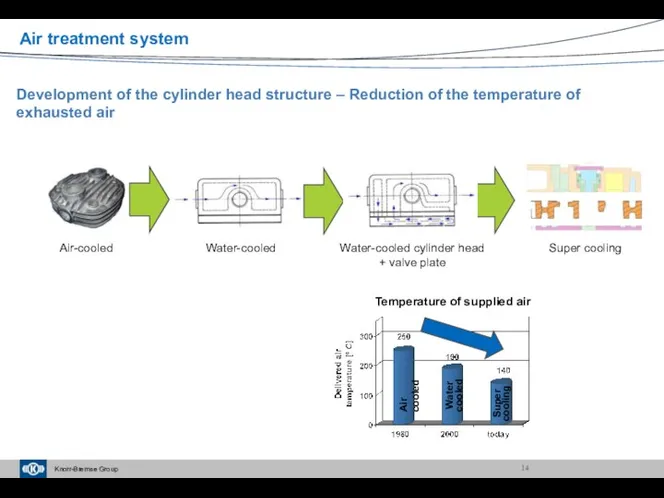
Development of the cylinder head structure – Reduction of the temperature
Development of the cylinder head structure – Reduction of the temperature
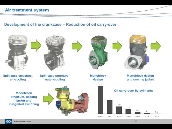
Development of the crankcase – Reduction of oil carry-over
Split-case structure, air-cooling
Monoblock
Development of the crankcase – Reduction of oil carry-over
Split-case structure, air-cooling
Monoblock
Tester for oil carry-over
Power consumption
Delivery performance
Maintenance need:
In the case of
Tester for oil carry-over
Power consumption
Delivery performance
Maintenance need:
In the case of
Air treatment system
Installation sample for switchable compressor
Switchable compressor
Air dryer
Switching device
Solenoid valve
Sensor
1.
Air treatment system
Installation sample for switchable compressor
Switchable compressor
Air dryer
Switching device
Solenoid valve
Sensor
1.
Air treatment system
Air treatment system

Compressors – Current service information
Air treatment system
Compressors – Current service information
Air treatment system
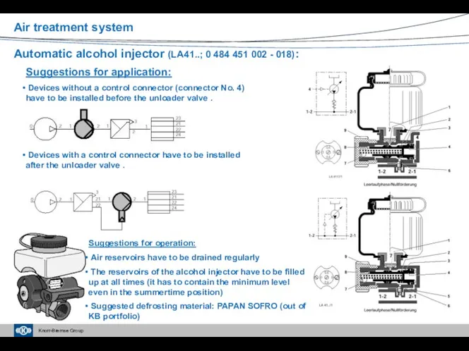
Automatic alcohol injector (LA41..; 0 484 451 002 - 018):
Suggestions for
Automatic alcohol injector (LA41..; 0 484 451 002 - 018):
Suggestions for
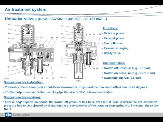
Unloader valves (DR35..; AC135..; 0 481 039 …; 0 481 042
Unloader valves (DR35..; AC135..; 0 481 039 …; 0 481 042
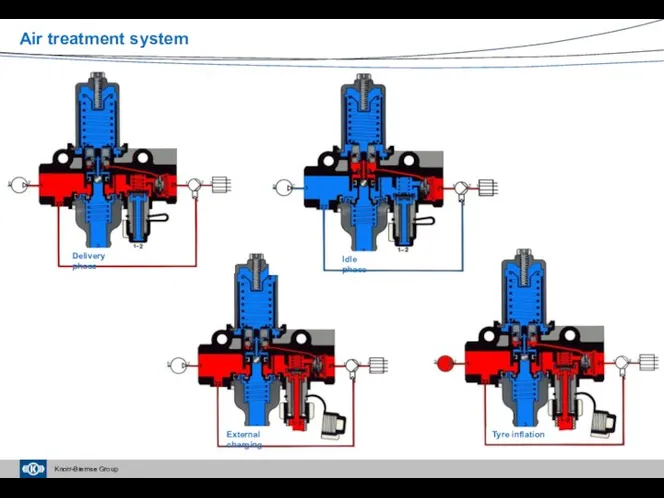
Delivery phase
Air treatment system
Idle phase
External charging
Tyre inflation
Delivery phase
Air treatment system
Idle phase
External charging
Tyre inflation
Air treatment system
Using a unloader valve in the case of an
Air treatment system
Using a unloader valve in the case of an
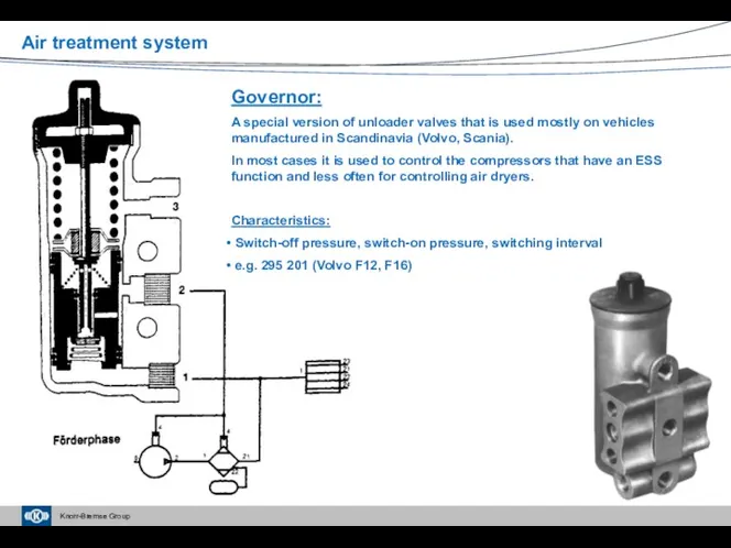
Governor:
A special version of unloader valves that is used mostly
Governor:
A special version of unloader valves that is used mostly
Air treatment system
Air dryer (LA60..; LA62..; LA67..; LA80..; LA82..; LA9…):
Advantages:
Reduced
Air treatment system
Air dryer (LA60..; LA62..; LA67..; LA80..; LA82..; LA9…):
Advantages:
Reduced
Air treatment system
Choosing the reservoir size:
1 Switch-off pressure
2 Total volume of
Air treatment system
Choosing the reservoir size:
1 Switch-off pressure
2 Total volume of
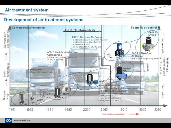
Increasing complexity
1980
1995
2000
2005
2010
2015
1985
1990
Development of air treatment systems
2020
Compact
design
Multi-
functionality
Serviceability
and fuel saving
Technology
Pneumatics
Pneumatics with
int. electronics
Electro-pneumatic
Compact
Increasing complexity
1980
1995
2000
2005
2010
2015
1985
1990
Development of air treatment systems
2020
Compact
design
Multi-
functionality
Serviceability
and fuel saving
Technology
Pneumatics
Pneumatics with
int. electronics
Electro-pneumatic
Compact
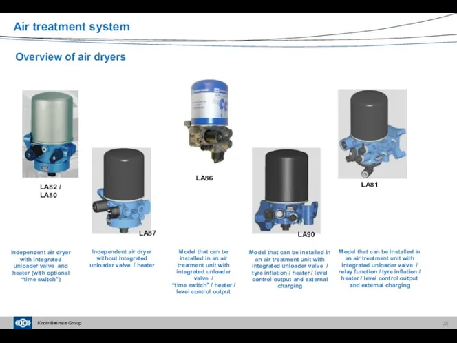
LA86
LA87
LA82 / LA80
Overview of air dryers
LA90
LA81
Independent air dryer with integrated unloader
LA86
LA87
LA82 / LA80
Overview of air dryers
LA90
LA81
Independent air dryer with integrated unloader
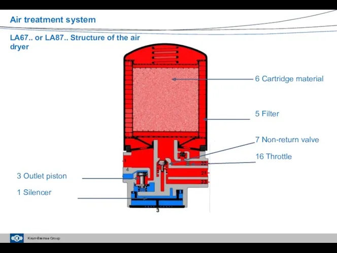
6 Cartridge material
5 Filter
7 Non-return valve
16 Throttle
3 Outlet piston
1 Silencer
4
LA67.. or
6 Cartridge material
5 Filter
7 Non-return valve
16 Throttle
3 Outlet piston
1 Silencer
4
LA67.. or
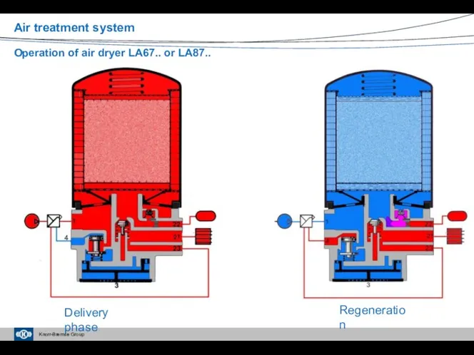
4
Delivery phase
Regeneration
Air treatment system
Operation of air dryer LA67.. or LA87..
4
Delivery phase
Regeneration
Air treatment system
Operation of air dryer LA67.. or LA87..
Air treatment system
Structure of air dryer LA82..
Air treatment system
Structure of air dryer LA82..
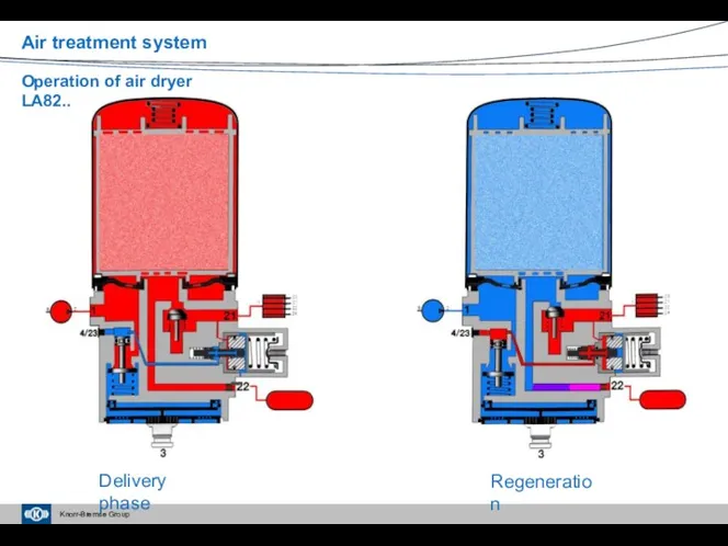
Delivery phase
Regeneration
Air treatment system
Operation of air dryer LA82..
Delivery phase
Regeneration
Air treatment system
Operation of air dryer LA82..
Delivery phase
b
c
Air treatment system
Structure of air dryer LA80..
Delivery phase
b
c
Air treatment system
Structure of air dryer LA80..
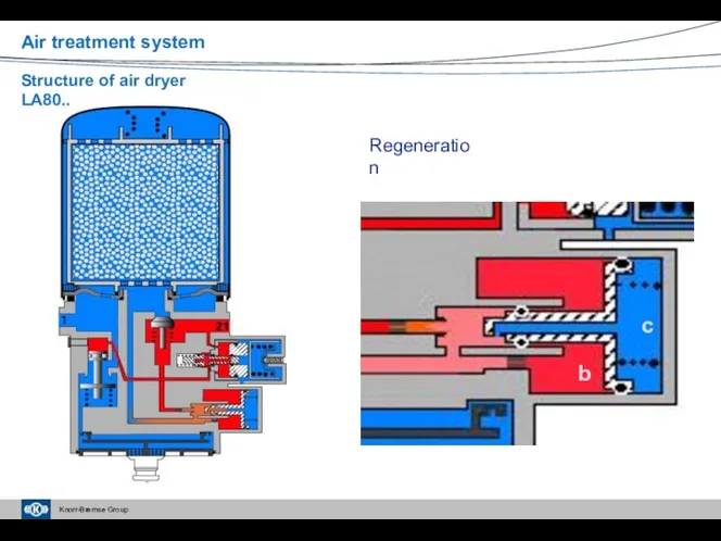
Regeneration
b
c
Air treatment system
Structure of air dryer LA80..
Regeneration
b
c
Air treatment system
Structure of air dryer LA80..
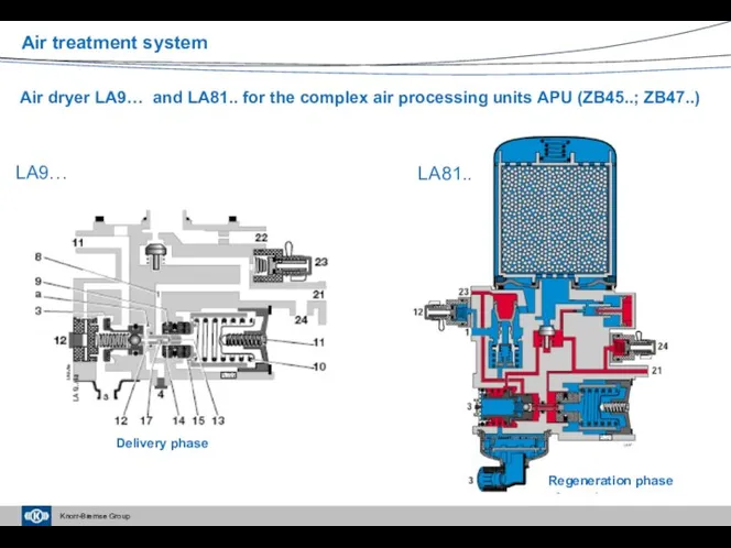
Air dryer LA9… and LA81.. for the complex air processing units
Air dryer LA9… and LA81.. for the complex air processing units
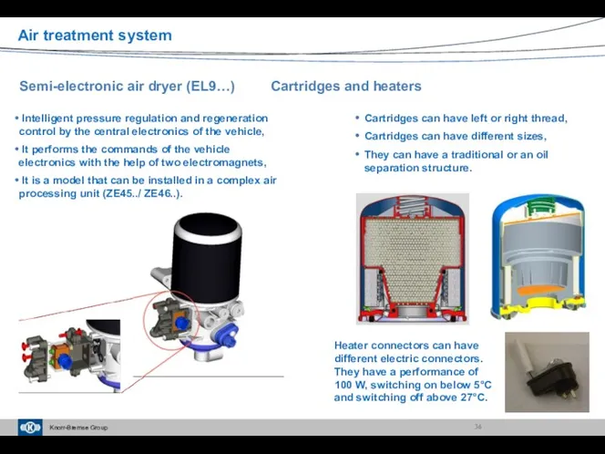
Semi-electronic air dryer (EL9…) Cartridges and heaters
Intelligent pressure regulation and regeneration
Semi-electronic air dryer (EL9…) Cartridges and heaters
Intelligent pressure regulation and regeneration
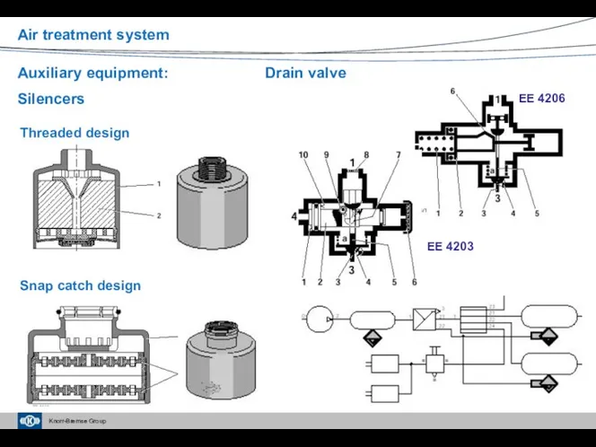
Auxiliary equipment: Drain valve
Silencers
Threaded design
Snap catch design
EE 4206
EE 4203
Air treatment system
Auxiliary equipment: Drain valve
Silencers
Threaded design
Snap catch design
EE 4206
EE 4203
Air treatment system
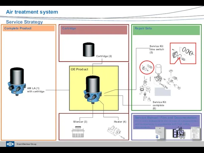
Cartridge
Service Manual / Film and Documentation
For a quick replacement and service
Cartridge
Service Manual / Film and Documentation
For a quick replacement and service
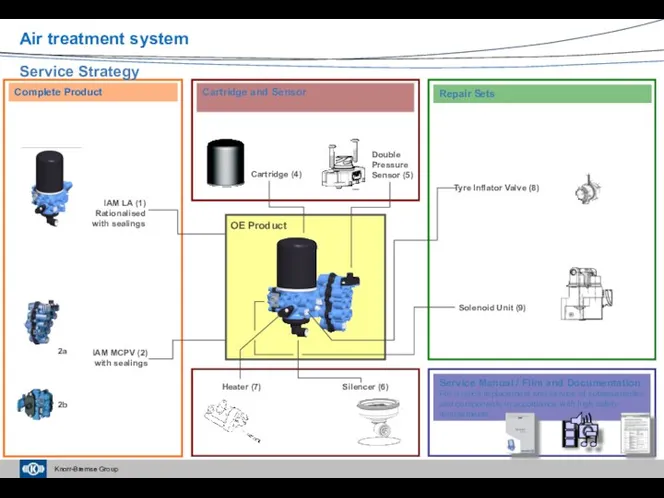
Cartridge (4)
Cartridge and Sensor
Double
Pressure
Sensor (5)
Service Manual / Film and
Cartridge (4)
Cartridge and Sensor
Double
Pressure
Sensor (5)
Service Manual / Film and
Air dryer units – Current service information
Air treatment system
Air dryer units – Current service information
Air treatment system
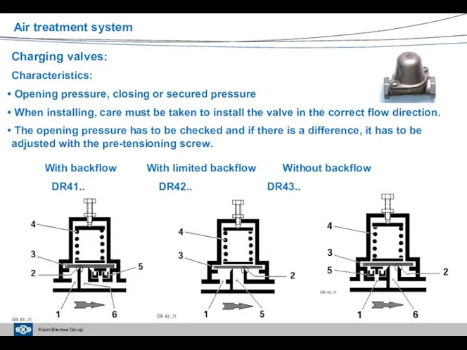
Charging valves:
Characteristics:
Opening pressure, closing or secured pressure
When installing, care
Charging valves:
Characteristics:
Opening pressure, closing or secured pressure
When installing, care
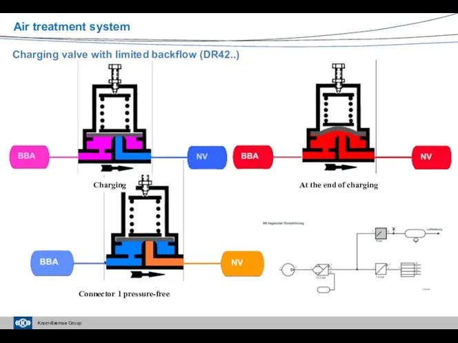
Charging valve with limited backflow (DR42..)
Air treatment system
Charging
At the end of
Charging valve with limited backflow (DR42..)
Air treatment system
Charging
At the end of
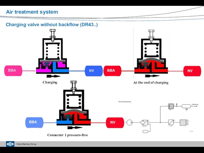
Charging valve without backflow (DR43..)
Air treatment system
Connector 1 pressure-free
At the end
Charging valve without backflow (DR43..)
Air treatment system
Connector 1 pressure-free
At the end
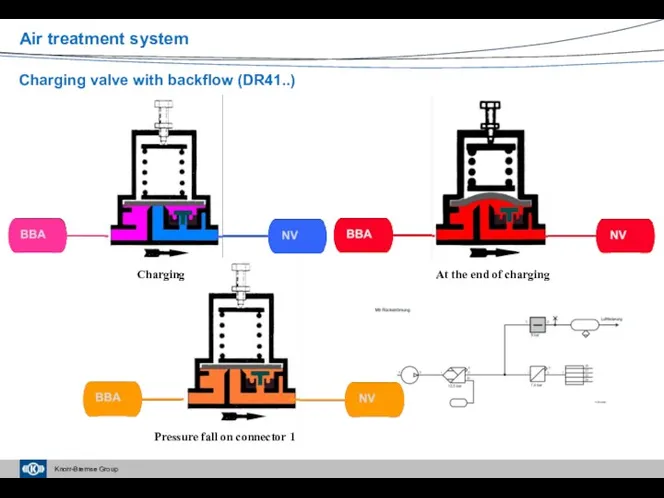
Charging valve with backflow (DR41..)
Air treatment system
Pressure fall on connector 1
At
Charging valve with backflow (DR41..)
Air treatment system
Pressure fall on connector 1
At
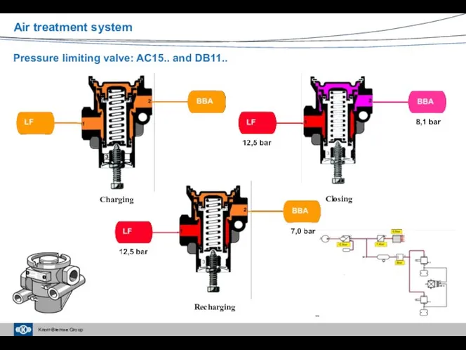
Pressure limiting valve: AC15.. and DB11..
Air treatment system
Recharging
Charging
Closing
Pressure limiting valve: AC15.. and DB11..
Air treatment system
Recharging
Charging
Closing
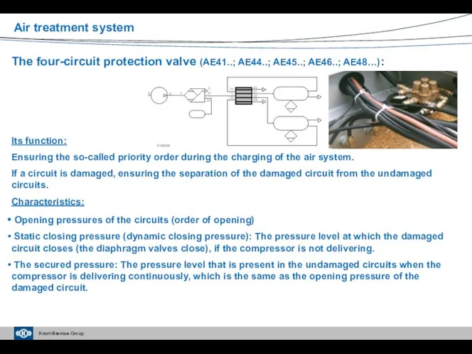
The four-circuit protection valve (AE41..; AE44..; AE45..; AE46..; AE48…):
Its function:
Ensuring
The four-circuit protection valve (AE41..; AE44..; AE45..; AE46..; AE48…):
Its function:
Ensuring
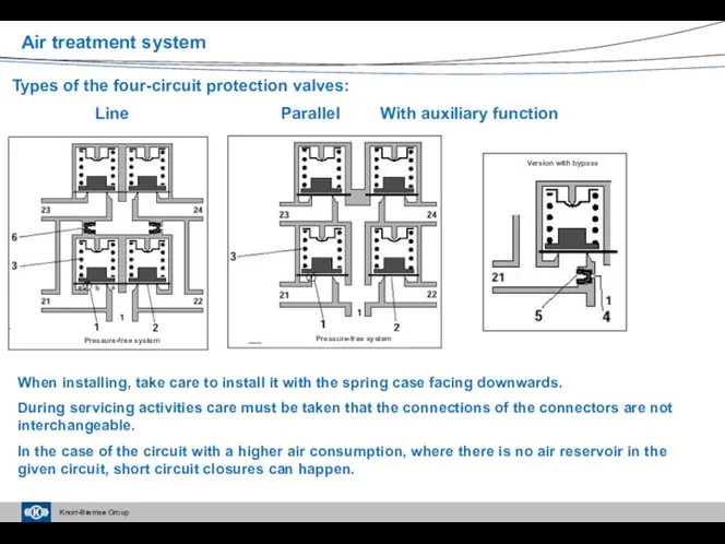
Types of the four-circuit protection valves:
Line Parallel With auxiliary function
When installing,
Types of the four-circuit protection valves:
Line Parallel With auxiliary function
When installing,
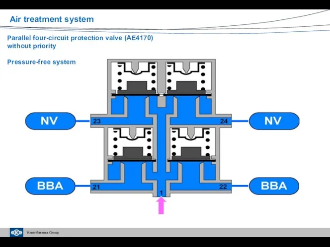
Parallel four-circuit protection valve (AE4170)
without priority
Pressure-free system
Air treatment system
Parallel four-circuit protection valve (AE4170)
without priority
Pressure-free system
Air treatment system
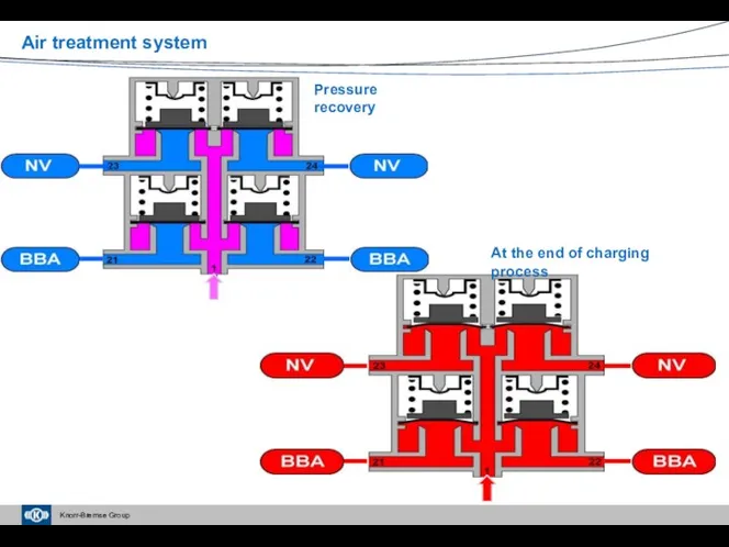
At the end of charging process
Air treatment system
Pressure recovery
At the end of charging process
Air treatment system
Pressure recovery
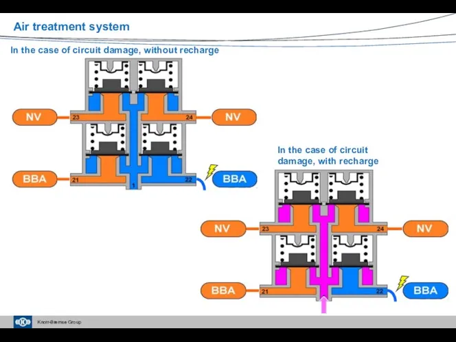
In the case of circuit damage, without recharge
In the case of
In the case of circuit damage, without recharge
In the case of
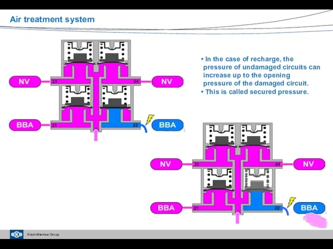
In the case of recharge, the pressure of undamaged circuits
In the case of recharge, the pressure of undamaged circuits
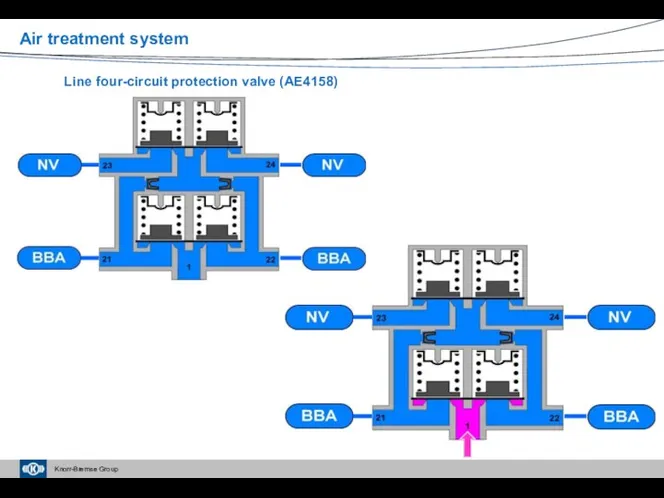
Line four-circuit protection valve (AE4158)
Air treatment system
Line four-circuit protection valve (AE4158)
Air treatment system
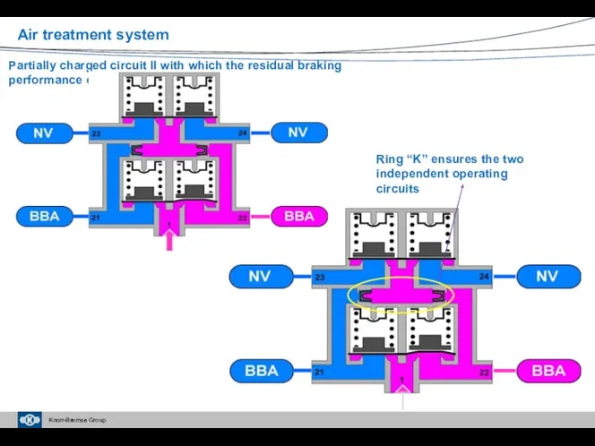
Partially charged circuit II with which the residual braking performance can
Partially charged circuit II with which the residual braking performance can
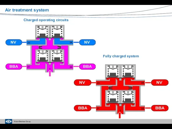
Charged operating circuits
Fully charged system
Air treatment system
Charged operating circuits
Fully charged system
Air treatment system
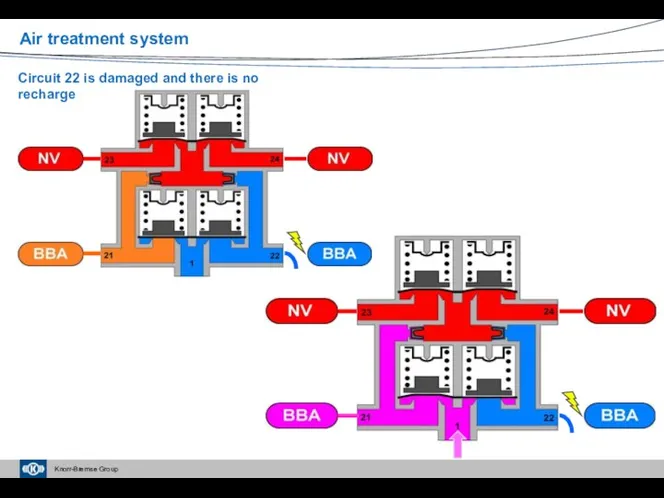
Circuit 22 is damaged and there is no recharge
Air treatment system
Circuit 22 is damaged and there is no recharge
Air treatment system
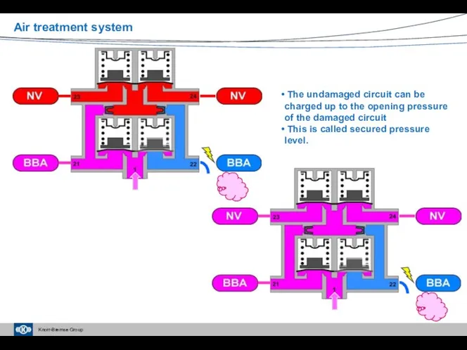
The undamaged circuit can be charged up to the opening
The undamaged circuit can be charged up to the opening
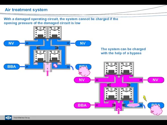
With a damaged operating circuit, the system cannot be charged if
With a damaged operating circuit, the system cannot be charged if
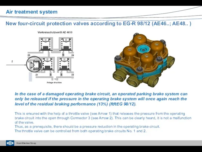
New four-circuit protection valves according to EG-R 98/12 (AE46..; AE48.. )
In
New four-circuit protection valves according to EG-R 98/12 (AE46..; AE48.. )
In
Charging of the system
Air treatment system
Charging of the system
Air treatment system
Full charging of the system
Air treatment system
Full charging of the system
Air treatment system
Operating the brake circuit in the case of “failure”, without charging
Air
Operating the brake circuit in the case of “failure”, without charging
Air
Multi-circuit protection valves
AE45 /47
AE48
AE46
Independent or can be installed in an air
Multi-circuit protection valves
AE45 /47
AE48
AE46
Independent or can be installed in an air
Air treatment system
Operation of AE45..
Clutch / Engagement
Other user
Trailer brake
Air treatment system
Operation of AE45..
Clutch / Engagement
Other user
Trailer brake
Air treatment system
Clutch / Engagement
Other user
Trailer brake
Operating circuits are open
Air treatment system
Clutch / Engagement
Other user
Trailer brake
Operating circuits are open
Air treatment system
Clutch / Engagement
Other user
Trailer brake
The pressure limiting valve starts
Air treatment system
Clutch / Engagement
Other user
Trailer brake
The pressure limiting valve starts
Air treatment system
Clutch / Engagement
Other user
Trailer brake
At a pressure of 10
Air treatment system
Clutch / Engagement
Other user
Trailer brake
At a pressure of 10
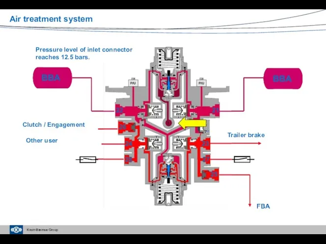
Air treatment system
Clutch / Engagement
Other user
Trailer brake
Pressure level of inlet connector
Air treatment system
Clutch / Engagement
Other user
Trailer brake
Pressure level of inlet connector
Four-circuit protection valves – Current service information
Air treatment system
Four-circuit protection valves – Current service information
Air treatment system
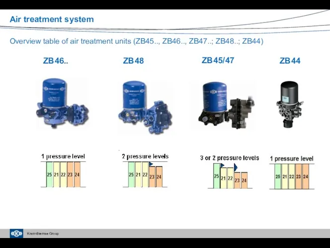
ZB46..
ZB48
ZB45/47
Overview table of air treatment units (ZB45.., ZB46.., ZB47..; ZB48..; ZB44)
ZB44
Air
ZB46..
ZB48
ZB45/47
Overview table of air treatment units (ZB45.., ZB46.., ZB47..; ZB48..; ZB44)
ZB44
Air
Complex air treatment units – Current service information
Air treatment system
Complex air treatment units – Current service information
Air treatment system
 Презентация Задачи и содержание педагогической диагностики индивидуального развития дошкольников в соответствии с требованиями ФГОС дошкольного образования
 Принцип работы новых контрольно-измерительных аппаратов
 Национальная и конфессиональная политика в Республике Калмыкия
 классификация химических реакций.
 Национализм. Подходы к изученю национализма
 урок географии в 9 классе по теме Агропромышленный комплекс. Обобщение
 Деление десятичных дробей на натуральное число
 Правила и средства построения композиции при выполнении натюрморта
 Технология и организация строительных процессов
 Динамика макроэкономического развития. Проблемы инфляции и безработицы. (Лекция 6. Темы 8, 9)
 Неметаллы: общая характеристика
 Творческая работа ученицы 4 класса Ворстер Яны Моя мама
 презентация Баба-Яга
 Отчёт о работе профсоюзного бюро ИЭТ
 Александр II: начало правления. Крестьянская реформа 1861 г
 Презентация по теме Русский быт
 Робототехника. Виды робототехники
 Горилла. Конструктор
 родительское собрание Проявление агрессии
 модель успешного ученика
 Смайлики
 Возникновение единиц в древности
 Презентация (2)
 Презентация На лугу Диск Диск
 Поведение газа в скважине. (Лекция 4)
 Ряд Фурье и интеграл Фурье
 P770 disassembly guide
 ООП. Часть 3. Полиморфизм