- Apparatus of installations with fluidized layer of pulverized catalyst. Introduction

Содержание
- 2. Plan Introduction; Main features of the process; Conclusion;
- 3. The advantages of this type of cracking compared to cracking, which uses a ball catalyst, are:
- 4. There are four main schemes of the reactor unit: The scheme with a double rise of
- 5. Scheme with the location of the reactor and regenerator on the same level. The catalyst is
- 6. Scheme of the reactor with a pulverized catalyst:1-raw material and catalyst distribution zone; 2-reaction zone; 3-settling
- 8. Скачать презентацию
Plan
Introduction;
Main features of the process;
Conclusion;
Plan
Introduction;
Main features of the process;
Conclusion;
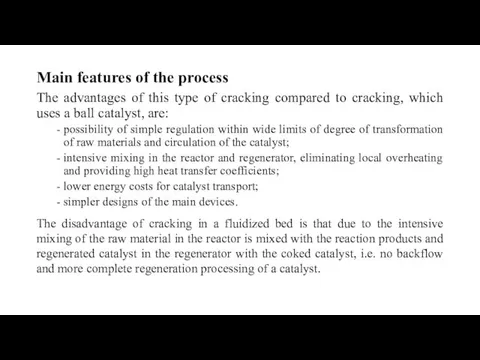
The advantages of this type of cracking compared to cracking, which
The advantages of this type of cracking compared to cracking, which
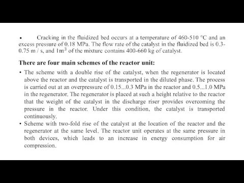
There are four main schemes of the reactor unit:
The scheme with
There are four main schemes of the reactor unit:
The scheme with
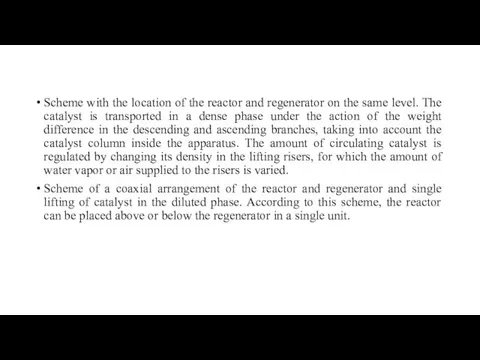
Scheme with the location of the reactor and regenerator on the
Scheme with the location of the reactor and regenerator on the
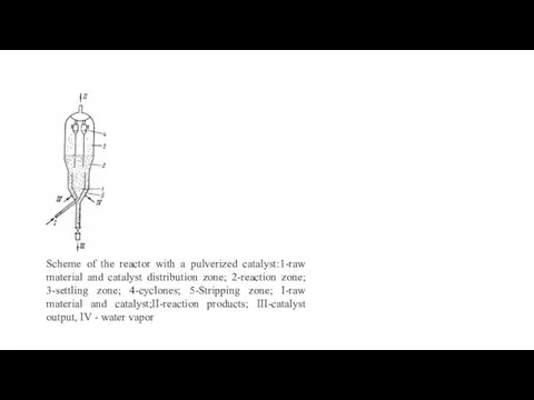
Scheme of the reactor with a pulverized catalyst:1-raw material and catalyst
Scheme of the reactor with a pulverized catalyst:1-raw material and catalyst
 Information and communication technology news. Neural processors
 Самообразование ТРИЗ - школа творческой личности
 Классы автомобилей которые участвуют в соревнованиях Формула студент
 Григорий Остер - Детям
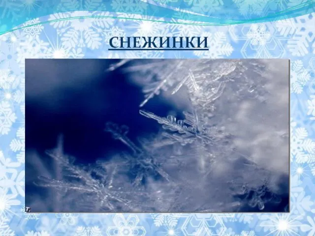 Снежинки
 VII Всероссийский конкурс фоторабот Летнее вдохновение(дети дошкольного возраста) Детские улыбки
 Республика Ботсвана
 Системно-деятельностный подход
 Русская народная сказка Иван-царевич и Серый волк
 ООО Телерадиокомпания 2х2
 Усвоение - основа учебной деятельности
 РЖД сегодня
 Культурологическая концепция П. Сорокина
 Накшатры Девы
 Ответственность в хозяйственном праве
 знаете ли вы?
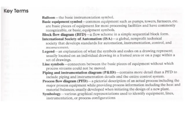 Process diagram and instrument sketching
 Татарский Новый год
 День смеха
 Периферическая нервная система
 Мультимедийная презентация. Дидактическое пособие своими руками Чудо мешочки
 Семейная реликвия
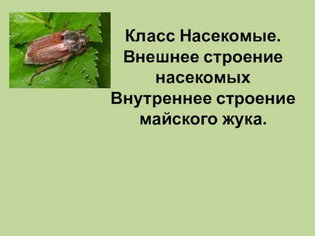 Класс Насекомые. Внешнее строение насекомых. Внутреннее строение майского жука
 Исследовательский проект Пока мы помним...( Бургоякова, Ильина, Петричук)
 Потенциал электростатического поля. Разность потенциалов. Эквипотенциальные поверхности
 СЮЖЕТНО-РОЛЕВАЯ ИГРА.
 Язык JavaScript, введение
 Формирование компетенций в области инклюзивного образования у родителей учащихся I ступени общего среднего образования